Abstract
The development of surface enhanced Raman scattering (SERS) detection has made Raman spectroscopy relevant for highly sensitive lab-on-a-chip bio/chemical sensors. Despite the tremendous benefit in specificity that a Raman-based sensor can deliver, development of a lab-on-a-chip SERS tool has been limited thus far. In this work, we utilize an optofluidic ring resonator (OFRR) platform to develop a SERS-based detection tool with integrated microfluidics. The liquid core optical ring resonator (LCORR) serves both as the microfluidic sample delivery mechanism and as a ring resonator, exciting the metal nanoclusters and target analytes as they pass through the channel. Using this OFRR approach and R6G as the analyte, we have achieved a measured detection limit of 400 pM. The measured Raman signal in this case is likely generated by only a few hundred R6G molecules, which foreshadows the development of a SERS-based lab-on-a-chip bio/chemical sensor capable of detecting a low number of target analyte molecules.
1. Introduction
A number of bio/chemical sensing techniques have been under development in recent years, including techniques that rely on fluorescent labeling and those that perform detection using label-free mechanisms such as refractive index or electrochemical effects. Of particular interest are platforms that are suited for lab-on-a-chip integration. Techniques based on Raman spectroscopy historically have not been applied for low-detection-limit lab-on-a-chip systems because the Raman scattering cross-section of analytes is far too small for highly sensitive detection in practical lab-on-a-chip platforms. However, the development of surface-enhanced Raman scattering (SERS) techniques has made it possible to combine the highly specific nature of Raman spectroscopy with the high-throughput and sample handling advantages of lab-on-a-chip technology.
Modern research on SERS dates back approximately 30 years to the discovery of Raman signal enhancement due to metal nanostructures [1,2]. Later, Kerker, et al., analyzed the SERS effect as an electromagnetic enhancement using a simple dipole model for localized surface plasmons in the metal nanostructures [3]. More recently, the SERS effect has been studied as both an electromagnetic and a chemical enhancement [4]. Ultimately, the intensive research on SERS detection has led to several demonstrations of single molecule detection with Raman enhancements as high as 1014 [4–6].
Translation of these spectacular results to lab-on-a-chip platforms with integrated microfluidics is still in progress. In recent years, microfluidic-based SERS platforms have been demonstrated in which the sample is optically excited inside a small sample delivery channel [7–10]. In references [7,8], specialized fiber cables are used as both the microfluidic sample delivery mechanism and the Raman pump/signal waveguide, while reference [9] is of particular interest for lab-on-a-chip development, as it uses a liquid core waveguide integrated onto a chip. The resulting detection limits achieved thus far with these approaches are on the order of 10 nM to 1 μM.
In the approach presented here, an optofluidic ring resonator (OFRR) design is used to achieve a detection limit of 400 pM with R6G in silver colloid. We use the liquid core optical ring resonator (LCORR), which was first demonstrated as a refractometric sensing platform and later a label-free biomolecule detection platform with integrated microfluidics [11,12]. More recently, the LCORR has been used as an optofluidic dye laser platform with a low threshold [13].
The LCORR uses a micro-sized glass capillary with a thin wall as both the microfluidic channel and as an optical ring resonator. As illustrated in Fig. 1, light repeatedly travels around the circumference of the capillary in the form of whispering gallery modes (WGMs). Certain wavelengths resonate with observed Q-factors higher than 107 in some cases [13]. If the wall is as thin as a few microns, an evanescent field exists at the inner surface of the capillary and interacts with the sample as it passes through the capillary. Because of the high Q-factor, this evanescent field forms a high-intensity field capable of acting as a SERS excitation source. As the sample flows through the LCORR capillary, analytes that pass through the ring resonator evanescent field may produce Raman scattered photons. Furthermore, analytes that are adsorbed onto silver nanoparticles can produce a SERS signal due to the electromagnetic and chemical enhancement mechanisms.
Fig. 1.
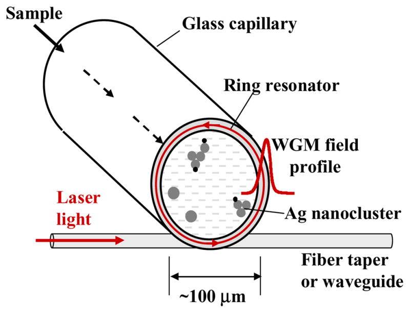
The LCORR uses a glass capillary to move the sample past the optical ring resonator, which is present in the circumference of the glass capillary wall.
The use of resonating WGMs for SERS has been investigated theoretically and experimentally [14–16]. We previously used a microsphere ring resonator to show experimentally a gain of over two orders of magnitude compared to a SERS system in which the excitation light makes a single or non-resonant pass through the sample volume [15]. Furthermore, by applying a theory of scattering by compound spheres, Fuller and Smith predict gains of 102 to 104 with the use of microspheres in SERS measurements [16]. In our system design, the ring resonator is also a microfluidic channel, and the WGM excitation is separated from the sample, making the detection system more practical and adaptable than the microsphere to a lab-on-a-chip design [17].
2. Experimental setup
Solutions of Rhodamine 6G (R6G) in silver colloid are used as model samples in the experiments presented here. R6G is selected as the target analyte because of its well-characterized Raman spectrum and its common use in other SERS investigations. The silver colloid is prepared using the reduction method originally introduced by Lee and Meisel [18]. To promote clustering, the silver colloid is mixed with a NaCl stock solution in water such that the silver colloid is diluted by a factor of three and the NaCl concentration is approximately 18 mM. Clustering of the silver nanoparticles is induced because individual silver nanoparticles are typically resonant for wavelengths between 400 and 500 nm, while nanoclusters have an extended resonance into the near infrared, which is used in the experiments here. Furthermore, clustering is known to induce high-enhancement “hot spots,” regions of extremely high SERS enhancement due to the nanoparticle geometry [5, 6]. After adding NaCl, the aliquot is shaken for 30–60 minutes, and then R6G is added to produce a concentration of 333 nM. This solution is shaken for 30–60 minutes, and then dilutions are prepared. Samples are produced shortly before the experiments are conducted.
A scanning electron microscope (SEM) image of a particularly large silver cluster is shown in Fig. 2. The figure shows a relatively uniform nanoparticle size of approximately 50 nm in diameter, and it shows that a high degree of clustering can occur in our samples. It is estimated that the silver nanoparticle concentration in colloid is around 2 nM, and thus is sub-nM in the NaCl activated aliquot with R6G added. Therefore, the R6G concentration is over 100 times that of the silver nanoparticles. The ratio of R6G molecules to silver clusters is even higher, and thus it is expected that many silver clusters will have several target analyte molecules. Conversely, it is expected that many target analyte molecules are not adsorbed at hot spots of the silver clusters, making the effective analyte concentration smaller than the values given here. Nonetheless, working with a very low concentration (pM or lower) of silver nanoclusters is important because it is observed that at higher concentrations, the Q-factor of the LCORR is degraded, which compromises the resulting SERS signal.
Fig. 2.
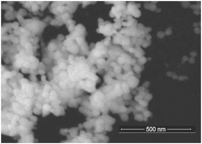
SEM of a large silver cluster within a typically prepared silver colloid solution. The solution is dried onto a TEM grid in preparation for imaging.
The samples are pumped into the LCORR using a peristaltic pump and attached tubing. The LCORR capillaries are produced from silica glass tubes as described in [19]. The diameter of the capillaries used is approximately 125 μm. The wall thickness of the capillaries is reduced to the desired values by passing a solution of hydrofluoric acid (HF) in water through the capillary, which slowly etches the capillary wall. The thickness of the wall and the penetration of the resonant WGM evanescent field beyond the inner surface are evaluated by characterizing the refractive index (RI) sensitivity of the LCORR, as described in [11].
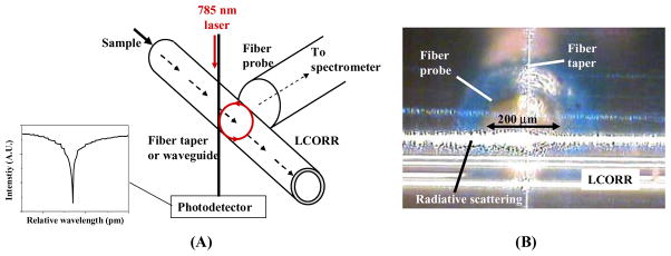
To perform the SERS measurement, a tapered fiber optic cable with a diameter of approximately 1–2 μm is brought into contact with the LCORR, as shown in Fig. 3. A 785 nm DFB laser (Toptica) is coupled into the fiber taper and excites resonant modes in the LCORR. As shown in Fig. 3(A), the modes can be observed at the taper output as intensity dips when the excitation laser is repeatedly scanned in frequency. In these experiments, the Q-factor is generally above 106, which enables many hundreds of revolutions for the average photon lifetime, as shown by the equation: N = Qλ/(4π2nR), where N is the average number of effective photon revolutions, R is the ring resonator radius, λ is the resonant wavelength in vacuum, and n is the resonator refractive index. The result is an intense optical field in the ring resonator. Using the well-known ring resonator coupling analysis in [20] and the fact that in the experiments presented here we typically observe 10% coupling from taper to LCORR (i.e. the dip shown in Fig. 3(A) is 10% of the maximum), it can be shown that the power in the ring resonator is approximately 25 times that in the taper. Also, if critical coupling can be achieved, the power in the ring resonator with a Q-factor of 106 is as much as 250 times that of the taper.
Fig. 3.
(A) Experimental setup for measuring the Raman scattering signal from the LCORR. (B) Snapshot showing the LCORR capillary, the fiber taper, and the fiber probe.
As described earlier, however, it is the evanescent field at the inner surface that interacts with the sample. For the LCORR, the evanescent field is typically about 1% of the total power in the ring resonator. Although the power in the evanescent field is therefore similar to the power in the excitation taper, for Raman spectroscopy it is the intensity of the field that matters. Because the field protrudes only 100 nm into the sample, a high intensity can be achieved, particularly when a high degree of longitudinal confinement exists. This is the reason behind the excellent results predicted and achieved with microsphere-based SERS [15,16].
In addition to orbiting the circumference of the LCORR, the high-Q resonant modes also propagate a short distance along the longitudinal axis. In fact, in Fig. 3(B), radiatively scattered light can be seen along the top of the LCORR. As a result, the Raman signal is generated across a longitudinal distance of approximately 1 mm. To collect the Raman scattered light, a polished multimode fiber is placed adjacent to the LCORR at the region of excitation. The location and angle are optimized to reduce the collection of radiative scattering from the WGM while not compromising the collection of Raman scattered photons. The probe fiber directs the photons to the spectrometer, where they first pass through a collimating lens, a high-pass Raman filter, and a focusing lens. A Triax 550 (Jobin Yvon) spectrometer with a resolution of 0.15 nm is used to analyze the Raman signal.
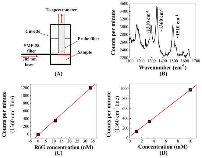
To characterize the Raman scattering signal from the sample to measure the average Raman enhancement due to the silver colloid, we use the experimental setup illustrated in Fig. 4, which is easily comparable with the LCORR experimental setup. An SMF-28 fiber cable is glued into a cuvette to deliver excitation light to the sample. The same probe fiber used in the LCORR measurements is placed just above the beam of light coming from the excitation fiber. Figure 4(B) shows the Raman signal measured with 33 nM R6G in the clustered silver colloid. Spectral lines are clearly visible at 1310 cm−1, 1360 cm−1, and 1510 cm−1, which are characteristic of R6G. Figures 4(C) and (D) show the peak intensity in the 1360 cm−1 line versus R6G concentration for cases with and without silver colloid, respectively. For this particular sample, the SERS enhancement is approximately 3 × 10⁵, according to a comparison using the 1360 cm−1 line. Typical values of enhancement observed during these experiments vary from around 3 × 10⁵ up to 106.
Fig. 4.
(A) Experimental setup to characterize the SERS enhancement of the Ag colloid. (B) Measured Raman spectrum for 33 nM R6G in Ag colloid using the setup in (A). (C) Raman intensity versus R6G concentration in Ag colloid using the setup in (A). Each data point is the peak value of the characteristic R6G 1360 cm−1 Raman line for at least two averaged spectra. (D) Raman intensity versus R6G concentration in water. Again, each point is the peak value of the 1360 cm−1 line.
3. SERS detection results
3.1 WGM evanescent field is the excitation source
In this microfluidic-based SERS detection platform, the resonant WGM is used to excite the localized surface plasmons in the silver nanoclusters and subsequently the target analytes adsorbed to the silver. Only the evanescent field of the WGM at the capillary inner surface interacts with the sample, as the rest of the light exists in the glass or at the outer surface. Thus, the Raman signal is expected to be directly related to the optical intensity of the evanescent field, which is increased for thinner capillary walls.
To verify that in fact the WGM serves as the Raman excitation source in our LCORR design, we measured the Raman signal for an LCORR while decreasing the wall thickness, which enables a higher fraction of light in the evanescent field. The first measurement was performed using the LCORR immediately after the capillary had been pulled. The wall thickness at this point is greater than 10 μm, which is too thick to enable an evanescent field at the LCORR inner surface. As anticipated, no R6G Raman signal is apparent from this measurement. The capillary wall is then etched using HF, and RI sensitivity characterizations are performed to evaluate the strength of the evanescent field at the inner surface, as the RI sensitivity is directly related to the fraction of optical intensity that is in the sensing liquid [12].
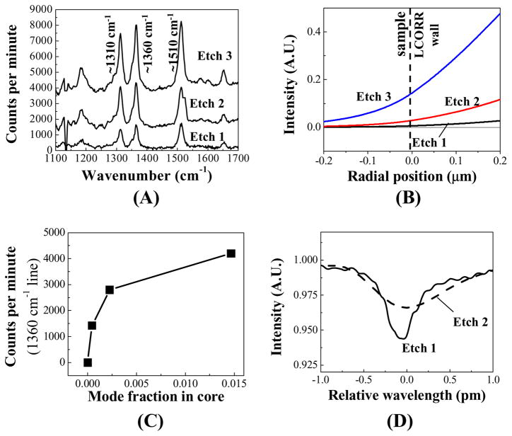
The measured Raman signals for three increasing RI sensitivities are presented in Fig. 5(A). As expected, the measured Raman signal for R6G increases as the LCORR becomes more sensitive, implying that a stronger evanescent field is interacting with the sample. From the RI sensitivity, the LCORR wall thickness and the fraction of intensity in the evanescent field can be calculated using a computational tool based on Mie theory [11]. Figure 5(B) shows the calculated intensity distributions of the resonant WGMs near the LCORR inner surface for each of the three wall thicknesses characterized.
Fig. 5.
(A) Measured Raman spectra for 33 nM R6G in the LCORR during different time points after etching the wall thickness of the LCORR capillary. Curves are vertically shifted for clarity. (B) Calculated WGM intensity profile at the LCORR inner surface based on the measured sensitivity at the different etching time points. Calculation parameters: outer diameter = 125 μm; etch 1: wall thickness = 3.3 μm, resonant wavelength = 784.55885 nm, angular momentum term = 698; etch 2: wall thickness = 2.85 μm, resonant wavelength = 784.2459 nm, angular momentum term = 698; etch 3: wall thickness = 2.15 μm, resonant wavelength = 783.6377 nm, angular momentum term = 696. (C) Raman intensity versus the fraction of the mode intensity in the core as calculated in (B). Each data point is the peak value of the 1360 cm−1 line. (D) The recorded WGM following etches 1 and 2. Etch 1 Q-factor is 1.6×10⁶, etch 2 Q-factor is 7.3×10⁵.
The peak intensity in the 1360 cm−1 R6G Raman line is plotted in Fig. 5(C) for each sensitivity, where the horizontal axis represents the ratio of light intensity in the evanescent field. The trend is not linear, though this is to be expected. Although the fraction of light inside the LCORR increases, the additional etching reduces the Q-factor due to surface roughness and an increased exposure of the WGM light to the water, which has significant absorption at 785 nm. Figure 5(D) plots the observed resonant modes recorded after the first etch and the second etch. While the mode fraction in the core increases by a factor of 5, the Q-factor decreases from 1.6×10⁶ to 7.3×10⁵. The decreasing Q-factor results in a lower intensity in the ring resonator, which can also be visualized by the decrease in the amount of light coupled back into the taper, as indicated by the lower coupling depth in Fig. 5(D). The combination of the increasing evanescent mode fraction and the decreasing Q-factor results in a net increase in evanescent intensity of just over 2, which matches with the increase in measured SERS signal in Fig. 5(C). This experimental result emphasizes the role of the evanescent field and the resonator Q-factor on the measured Raman signal.
3.2. SERS signal depends linearly on WGM input intensity
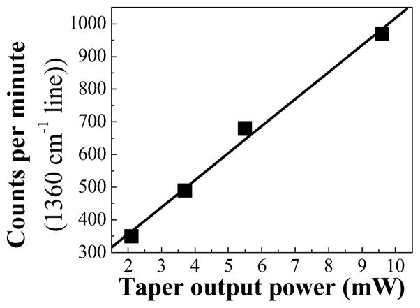
It is well known that the Raman scattered power depends linearly on the excitation intensity, the number of target analytes in the excitation volume, and the Raman scattering cross section of the target analyte. In this design, the excitation light intensity is a result of the 785 nm laser coupling from the fiber taper into the resonant WGMs and then coupling from the WGMs into the surface plasmons. We measured the R6G Raman signal from the LCORR while increasing the power of the excitation laser. In Fig. 6, the peak intensity in the 1360 cm−1 R6G line is plotted versus the measured output power of the fiber taper. As anticipated, the Raman scattering signal is linearly dependent upon the optical intensity in the fiber taper.
Fig. 6.
Raman intensity from the LCORR versus optical power passing through the fiber taper for 33 nM R6G in Ag colloid. Each data point is the peak value of the 1360 cm−1 line for the average of at least two measured spectra.
3.3. SERS signal dependence on concentration in LCORR is not linear
Figure 4(C) shows that the Raman signal depends linearly on the R6G concentration when the cuvette-based measurement is performed. In a case where the R6G concentration is increasing while the silver concentration remains the same, a linear result is not expected, as the adsorption of R6G onto silver nanoclusters saturates. However, here we maintain a constant ratio of R6G and silver nanoparticles, which preserves the linear relationship in the cuvette measurement.
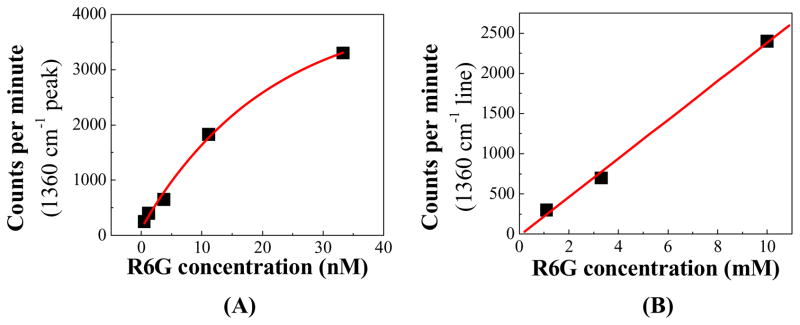
Performing the same concentration dependent measurement in the LCORR produces a different result. In Fig. 7(A), the Raman intensity is plotted for concentrations ranging from 410 pM to 33 nM, and shows an exponential decay. In contrast, Fig. 7(B) shows that when R6G in solution with no silver is analyzed inside the LCORR, the Raman signal is linear with R6G concentration. This implies that using a ring resonator as an excitation source does not directly result in a nonlinear behavior with respect to concentration.
Fig. 7.
(A) Raman intensity versus concentration with R6G in Ag colloid. Each data point is the peak value at 1360 cm−1 for at least two averaged spectra. Solid line is an exponential decay line fit. (B) Raman intensity versus concentration with R6G in water with no Ag nanoparticles. Again, each data point is the peak value at 1360 cm−1.
One possible explanation for the nonlinear behavior of the silver colloid R6G solution is the adsorption of silver onto the glass surface. As silver attaches to the inner surface of the LCORR, the concentration of analytes within the excitation volume increases beyond the bulk concentration. A second indicator of this possibility is that the observed SERS enhancement in the LCORR appears to be generally higher than the SERS enhancement in the cuvette-based characterization by a factor of between 2 and 5, depending on the concentration used for comparison. It is not likely that the use of the LCORR enhances the plasmonic or chemical effects of the silver, and thus the enhanced concentration effect due to adsorption of silver is a likely reason. Naturally, as the silver concentration in the bulk solution increases, the adsorption effect may experience saturation, just as the measured Raman signal exhibits in Fig. 7(A).
3.4. Measured detection limit of ~400 pM
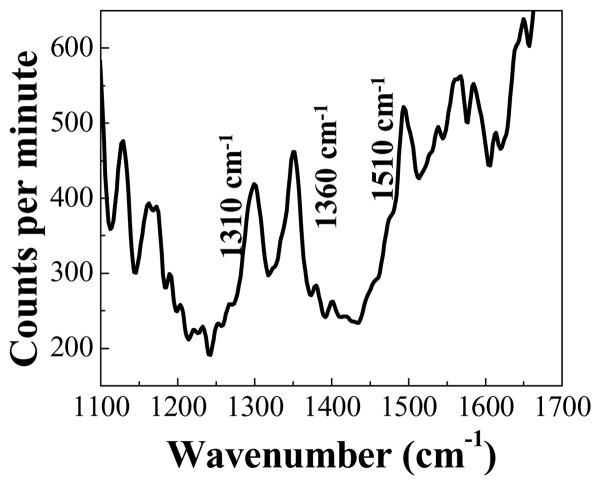
The measured Raman signal for the lowest concentration (410 pM) data point in Fig. 7(A) is shown in Fig. 8. The characteristic 1310 cm−1, 1360 cm−1, and 1510 cm−1 R6G Raman lines are clearly visible. The LCORR used in this experiment has a Q-factor of just over 106 and a RI sensitivity of 3.6 nm/RIU. The presumed detection volume includes the sample region illuminated by the WGM evanescent field that extends longitudinally across the diameter of the fiber probe (refer to Fig. 3). For an LCORR diameter of 125 μm, a longitudinal detection region of 200 μm, and an evanescent field penetration of 100 nm (see Fig. 5(B)), the detection volume is approximately 8 pL. For a bulk concentration of 400 pM, there are around 2000 R6G molecules within the detection region. In reality, many of these molecules are not adsorbed to the silver nanoclusters in high-enhancement locations. The number of silver nanoclusters within the detection volume is expected to be less than one on average, although adsorption of the silver clusters to the inner surface may increase this. Thus, it is estimated that the measured Raman signal shown in Fig. 8 is due to at most a few hundred R6G molecules adsorbed onto a low number of silver nanoclusters.
Fig. 8.
Measured Raman spectrum from 410 pM R6G in silver colloid. Trace is the average of six spectra with two minute integration time for each, and subsequent 5 point FFT smoothing. Background light at 1500 cm−1 and higher was not completely removed.
4. Summary and discussion
To develop a highly sensitive SERS detection platform with integrated microfluidics, we use a design based on an optofluidic ring resonator platform. Our design uses the LCORR glass capillary to deliver the sample to the sensor, which is an inherently integrated ring resonator. This low-volume microfluidic design is well suited for integration with sample preparation functions in a lab-on-a-chip platform. Additionally, the high-Q optical resonance results in a high-intensity SERS excitation source at the inner surface of the microfluidic capillary. The advantage can be seen by comparing the LCORR SERS result with the result obtained in the cuvette-based experiment (single-pass case), which uses the same laser for excitation and spectrometer for measurement. The LCORR demonstrated a signal at the 1360 cm−1 wavenumber of about 250 counts per minute. If we extrapolate the result from the cuvette-based experiment to this concentration, we could expect a signal of about 15 counts per minute, which demonstrates and improvement by a factor of over 15 by using the LCORR’s WGM evanescent field for SERS excitement.
Furthermore, the LCORR exhibits performance advantages compared to other microfluidic-based SERS platforms. We have achieved a measured detection limit of approximately 400 pM, which is significantly lower than other reported detection limits (10 nM – 1 μM) for other designs [8–10]. For this detection limit, it is likely that the measured Raman signal is due to no more than a few hundred target analytes on a low number of silver nanoclusters.
There are a number of opportunities for improvement. Results obtained previously with a microsphere ring resonator show a higher enhancement than the LCORR when both are compared to the single-pass case (greater than two orders of magnitude with the microsphere) because of higher Q-factor and better longitudinal confinement of the WGM intensity. Improved manufacturing techniques can improve the LCORR’s Q-factor, the fiber taper loss, and the coupling between the two. Also, working at a lower excitation wavelength can increase the SERS enhancement due to better matching of the plasmon resonance, and it would improve the LCORR Q-factor by reducing the optical absorption of water, which increases significantly beyond 700 nm. Furthermore, the intensity of excitation light in the resonant modes can be increased by improving the longitudinal confinement of the modes in the LCORR. This can be accomplished with a bottle geometry, as described in [21,22]. Improved Q-factor and longitudinal confinement would result in a SERS performance similar to that achieved with a microsphere, while leveraging the microfluidic advantages of the LCORR.
Finally, the apparent concentration enhancement due to adsorption of silver nanoclusters to the LCORR surface hints at using techniques such as de-protonation of the inner capillary surface to draw positively charged silver to the surface, where the high-Q optical resonance exists [23]. Additively, these improvements can result in an increased Raman signal by two orders of magnitude or more. This suggests the possibility of improving the LCORR’s SERS detection limit to the order of a few pM, and potentially to the detection of only a few target analyte molecules.
Acknowledgments
This work is sponsored by the Petroleum Research Fund (43879-G10), 3M Non-Tenured Faculty Award, the Wallace H. Coulter Foundation, and the NIH (1K25 EB006011). The authors thank the University of Missouri electron microscopy core for support.
Footnotes
References and links
- 1.Albrecht MG, Creighton JA. Anomalously intense Raman spectra of pyridine at a silver electrode. J Am Chem Soc. 1977;99:5215–5217. [Google Scholar]
- 2.Jeanmaire DL, Van Duyne RP. Surface Raman spectroelectrochemistry Part I. Heterocyclic, aromatic, and aliphatic amines adsorbed on the anodized silver electrode. J Electroanal Chem. 1977;84:1–20. [Google Scholar]
- 3.Kerker M, Wang DS, Chew H. Surface-enhanced Raman scattering (SERS) by molecules adsorbed at spherical particles. Appl Opt. 1980;19:4159–4174. doi: 10.1364/AO.19.004159. [DOI] [PubMed] [Google Scholar]
- 4.Michaels AM, Nirmal M, Brus LE. Surface enhanced Raman spectroscopy of individual rhodamine 6G molecules on large Ag nanocrystals. J Am Chem Soc. 1999;121:9932–9939. [Google Scholar]
- 5.Kneipp K, Wang Y, Kneipp H, Perelman LT, Itzkan I, Dasari RR, Feld MS. Single molecule detection using surface-enhanced Raman scattering (SERS) Phys Rev Lett. 1997;78 doi: 10.1103/PhysRevLett.76.2444. [DOI] [PubMed] [Google Scholar]
- 6.Nie S, Emory SR. Probing single molecules and single nanoparticles by surface-enhanced Raman scattering. Science. 1997;275:1102–1106. doi: 10.1126/science.275.5303.1102. [DOI] [PubMed] [Google Scholar]
- 7.Xu W, Xu S, Lü Z, Chen L, Zhao B, Ozaki Y. Ultrasensitive detection of 1, 4-Bis(4-vinylpyridyl)phenylene in a small volume of low refractive index liquid by surface-enhanced Raman scattering-active light waveguide. Appl Spectrosc. 2004;58:414–419. doi: 10.1366/000370204773580257. [DOI] [PubMed] [Google Scholar]
- 8.Yan H, Gu C, Yang C, Liu J, Jin G, Zhang J, Hou L, Yao Y. Hollow core photonic crystal fiber surface-enhanced Raman probe. Appl Phys Lett. 2006;89:204101. [Google Scholar]
- 9.Measor P, Seballos L, Yin D, Zhang JZ, Lunt EJ, Hawkins AR, Schmidt H. On-chip surface-enhanced Raman scattering detection using integrated liquid-core waveguides. Appl Phys Lett. 2007;90:211107. [Google Scholar]
- 10.Strehle KR, Cialla D, Rosch P, Henkel T, Kohler M, Popp J. A reproducible surface-enhanced Raman spectroscopy approach. Online SERS measurements in a segmented microfluidic system. Anal Chem. 2007;79:1542–1547. doi: 10.1021/ac0615246. [DOI] [PubMed] [Google Scholar]
- 11.White IM, Oveys H, Fan X. Liquid core optical ring resonator sensors. Opt Lett. 2006;31:1319–1321. doi: 10.1364/ol.31.001319. [DOI] [PubMed] [Google Scholar]
- 12.Zhu H, White IM, Suter JD, Dale PS, Fan X. Analysis of biomolecule detection with optofluidic ring resonator sensors. Opt Express. 2007;15:9139–9146. doi: 10.1364/oe.15.009139. http://www.opticsinfobase.org/abstract.cfm?URI=oe-15-15-9139. [DOI] [PubMed]
- 13.Shopova SI, Zhu H, Fan X, Zhang P. Optofluidic ring resonator based dye laser. Appl Phys Lett. 2007;90:221101. [Google Scholar]
- 14.Drachev VP, Kim WT, Khaliullin EN, Al-Zoubi F, Podolskiy VA, Safonov VP, Shalaev VM, Armstrong RL, Andreev AV, et al. Discrete spectrum of anti-stokes emission from metal particle-adsorbate cornplexes in a microcavity. Proc SPIE 4748, Fundamental aspects of laser-matter interaction and physics of nanostructures. 2001:380–389. [Google Scholar]
- 15.White IM, Fan X. Demonstration of composite microsphere cavity and surface enhanced Raman spectroscopy for improved sensitivity. In: Sedlacek AJ III, Christesen SD, Combs RJ, Vo-Dinh T, editors. Proc SPIE 5994, Chemical and biological sensors for industrial and environmental security. 2005. p. 59940G. [Google Scholar]
- 16.Fuller KA, Smith DD. Cascaded photoenhancement from coupled nanoparticle and microcavity resonance effects. Opt Express. 2007;15:3575–3580. doi: 10.1364/oe.15.003575. http://www.opticsinfobase.org/abstract.cfm?URI=oe-15-6-3575. [DOI] [PubMed]
- 17.White IM, Suter JD, Oveys H, Fan X. Universal coupling between metal-clad waveguides and optical ring resonators. Opt Express. 2007;15:646–651. doi: 10.1364/oe.15.000646. http://www.opticsinfobase.org/abstract.cfm?URI=oe-15-2-646. [DOI] [PubMed]
- 18.Lee PC, Meisel D. Adsorption and surface-enhanced Raman of dyes on silver and gold sols. J Phys Chem. 1982;86:3391–3395. [Google Scholar]
- 19.White IM, Suter JD, Zhu H, Oveys H, Brewington L, Gohring J, Fan X. Lab-on-a-chip bio/chemical sensing system based on the liquid core optical ring resonator. In: George T, Cheng Z, editors. Proc SPIE 6556, Micro (MEMS) and nanotechnologies for defense and security. 2007. p. 65560E. [Google Scholar]
- 20.Cai M, Painter O, Vahala KJ. Observation of critical coupling in a fiber taper to silica-microsphere whispering-gallery mode system. Phys Rev Lett. 2000;85:74–77. doi: 10.1103/PhysRevLett.85.74. [DOI] [PubMed] [Google Scholar]
- 21.Sumetsky M. Whispering-gallery-bottle microcavities: the three-dimensional etalon. Opt Lett. 2004;29:8–10. doi: 10.1364/ol.29.000008. [DOI] [PubMed] [Google Scholar]
- 22.Louyer Y, Meschede D, Rauschenbeutel A. Tunable whispering-gallery-mode resonators for cavity quantum electrodynamics. Phys Rev A. 2005;72:031801. [Google Scholar]
- 23.Park HK, Yoon JK, Kim K. Novel fabrication of Ag thin film on glass for efficient surface-enhanced Raman scattering. Langmuir. 2006;22:1626–1629. doi: 10.1021/la052559o. [DOI] [PubMed] [Google Scholar]


