Abstract
Microscale and nanoscale mechanical resonators have recently emerged as ubiquitous devices for use in advanced technological applications, for example, in mobile communications and inertial sensors, and as novel tools for fundamental scientific endeavours. Their performance is in many cases limited by the deleterious effects of mechanical damping. In this study, we report a significant advancement towards understanding and controlling support-induced losses in generic mechanical resonators. We begin by introducing an efficient numerical solver, based on the 'phonon-tunnelling' approach, capable of predicting the design-limited damping of high-quality mechanical resonators. Further, through careful device engineering, we isolate support-induced losses and perform a rigorous experimental test of the strong geometric dependence of this loss mechanism. Our results are in excellent agreement with the theory, demonstrating the predictive power of our approach. In combination with recent progress on complementary dissipation mechanisms, our phonon-tunnelling solver represents a major step towards accurate prediction of the mechanical quality factor.
 The performance of micromechanical and nanomechanical resonators is often hampered by mechanical damping. In this study, the authors demonstrate a numerical solver for the prediction of support-induced losses in these structures and verify experimentally the fidelity of this method.
Mechanical coupling of a suspended structure to its supports is a fundamental energy loss mechanism in micromechanical and nanomechanical resonators1. Referred to variously as clamping2 or anchor loss3, this process remains significant even in devices fabricated from high-quality materials operated in vacuum and at cryogenic temperatures, and is in fact unavoidable in any non-levitating system. Although much progress has been made towards the understanding of mechanical dissipation at the microscale and nanoscale2,4, obtaining reliable predictions for the fundamental design-limited quality factor, Q, remains a major challenge while direct experimental tests are scarce5,6,7. At the same time, the implementation of high-quality micromechanical and nanomechanical systems is becoming increasingly important for numerous advanced technological applications in sensing and metrology, with select examples including wireless filters3,8, on-chip clocks9, microscopy10,11,12,13 and molecular-scale mass sensing14,15, and recently for a new generation of macroscopic quantum experiments that involve mesoscopic mechanical structures16,17,18,19,20,21,22,23. Here, we introduce a finite-element-enabled numerical solver for calculating the support-induced losses of a broad range of low-loss mechanical resonators. We demonstrate the efficacy of this approach via comparison with experimental results from microfabricated devices engineered to isolate support-induced losses by allowing for a significant variation in geometry, while keeping other resonator characteristics approximately constant. The efficiency of our solver results from the use of a perturbative scheme that exploits the smallness of the contact area, specifically the recently introduced 'phonon-tunnelling' approach24. This results in a significant simplification over previous approaches and paves the way for CAD-based predictive design of low-loss mechanical resonators.
The origins of mechanical damping in microscale and nanoscale systems have been the subject of numerous studies during the last decades, and several relevant mechanisms for the decay of acoustic mechanical excitations, that is, phonons, have been investigated2,4. These include: (i) fundamental anharmonic effects such as phonon–phonon interactions4,25, thermoelastic damping (TED)4,25,26,27,28 and the Akhiezer effect4,25; (ii) viscous or fluidic damping involving interactions with the surrounding atmosphere or the compression of thin fluidic layers29,30,31; (iii) material losses driven by the relaxation of intrinsic or extrinsic defects in the bulk or surface of the resonator32,33,34,35,36,37 for which the most commonly studied model is an environment of two-level fluctuators38,39 and (iv) support-induced losses, that is, the dissipation induced by the unavoidable coupling of the resonator to the substrate3,7,8,40,41, which corresponds to the radiation of elastic waves into the supports5,6,24,42,43,44. This last mechanism poses a fundamental limit, as vibrations of the substrate will always be present.
These various dissipation processes add incoherently such that the reciprocals of the corresponding Q-values satisfy 1/Qtot=∑i1/Qi, where i labels the different mechanisms. Thus, in a realistic setting, care must be taken to isolate the contribution under scrutiny. In contrast to all other damping mechanisms (i–iii), which exhibit various dependencies with external physical variables such as pressure and temperature, support-induced dissipation is a temperature- and scale-independent phenomenon with a strong geometric character that is present in any suspended structure. Moreover, its scale independence implies that the same analysis can be applied to both microscale and nanoscale devices. We exploit this geometric character to isolate the support-induced contribution and obtain a direct experimental test of phonon-tunnelling dissipation.
The numerical solver we introduce provides a new technique to efficiently model support-induced losses for a broad class of mechanical structures. Previous approaches have relied on either the direct solution of an elastic wave radiation problem involving the substrate6,7,42,43,44 or the simulation of a perfectly absorbing artificial boundary5,41, with systematic tests as a function of geometry limited to a few specific cases5,6,7. In contrast, our technique represents a substantial simplification in that it reduces the problem to the calculation of a perfectly decoupled resonator mode together with free elastic wave propagation through the substrate in the absence of the suspended structure. A key feature of our method is to combine a standard finite-element method (FEM) calculation of the resonator mode together with the use of an extended contact at the support. This allows us to treat complex geometries, taking proper account of interference effects between the radiated waves.
In summary, we develop and test an efficient method for calculating the clamping loss of high-Q mechanical resonators. Our analysis includes a thorough experimental verification of this theoretical framework by employing resonators that are specifically designed to isolate the clamping-loss contribution to the total dissipation 1/Q. The measured damping in these structures matches the theoretical predictions and demonstrates in a direct manner the strong geometric character of this fundamental dissipation channel.
Results
Phonon-tunnelling approach
In analogy to radiation tunnelling in photonics and electron tunnelling in low-dimensional structures, we adopt a 'phonon tunnelling' picture to describe the support-induced losses24. In this picture, the mechanical resonance of interest, characterized by frequency ωR, is regarded as a phonon cavity that is weakly coupled to the exterior by a hopping process, whereby the elastic energy leaks out of the resonator through the narrow contact areas from which it is suspended. Within this framework, one can start from the harmonic Hamiltonian associated with the elastic scattering eigenmodes of the entire structure, including the substrate, and derive a quantum model for the Brownian motion experienced by each resonance of the suspended structure.
The corresponding weak tunnel couplings can be obtained to lowest order in the small parameter kRd, where 1/kR is the characteristic length scale over which the resonator mode varies appreciably and d is the characteristic dimension of the contact area S from which the resonator is suspended. For typical structures that exhibit high-Q mechanical resonances, kRd≪1 is comfortably satisfied. This justifies the weak coupling approximation and leads to a general expression for the associated dissipation 1/Q in terms of the 'overlaps' between the scattering modes and the resonator mode. In the limit d→0, the leading contribution is obtained by replacing the scattering modes by the free (unperturbed) modes of the supports, which yields24
 |
1 |
Here,  and
and  are the stress and displacement fields associated with the normalized resonator mode,
  and
and 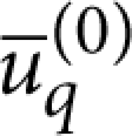 are the analogous fields for the continuum of support modes labelled by q (eigenfrequencies ω(q)), and ρs and ρR are, respectively, the densities of the substrate and resonator materials. The resonator mode should satisfy either (i) free or (ii) clamped boundary conditions at the contact area, S, depending on the behaviour of the eigenmode when S is small, whereas the unperturbed support modes should satisfy the converse. These homogeneous boundary conditions correspond, respectively, to
  and
and 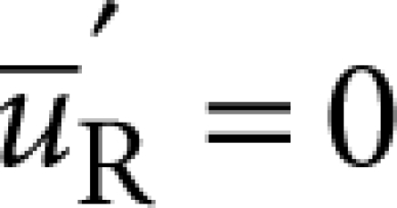 so that only one of the two terms in the surface integral is finite. In general, the decomposition between 'resonator volume' and 'supports' consistent with the weak coupling condition need not be unique. Examples of case (i) are pedestal geometries, such as microspheres, microdisks or microtoroids, when the pedestal is included in the support24. It is worth noting that for these geometries, if the pedestal is assumed to have perfect impedance match with the substrate, equation (1) leads to a particularly simple result for the Q of an axially symmetric resonance7,24, which has been verified in ref. 7 for the radial breathing mode of microtoroid structures. On the other hand, examples of case (ii) include the planar structures investigated here, when the resonator volume consists of the portion of the structure that is free-standing.
A rigorous derivation of equation (1) is given in ref. 24. Alternatively, if one uses a decomposition of the displacement field in terms of the unperturbed support modes and the discrete modes of the resonator volume, equation (1) follows simply from applying Fermi's Golden rule to phonon decay, with the interaction Hamiltonian between the resonator volume (labelled <) and the surrounding supports (labelled >) given by 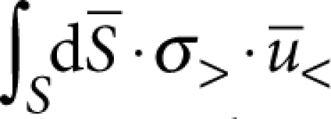 for case (i) and
  for case (ii). Within this framework, it is straightforward to realize that the validity of equation (1) is more general than the condition kRd≪1 and will also apply to any resonance, for which the support-induced frequency shift is small compared with the relevant mode spacing (that is, the free spectral range at the corresponding resonant frequency) so that the weak coupling assumption is warranted. For our case, the use of this master formula is completely equivalent to previous intuitive approaches based on forcing the substrate with the stress source generated by the resonator mode6,42,43,44, as can be shown rigorously by using—for the elastic Green's function of the substrate—a spectral decomposition in terms of its free modes. In the presence of mode coupling5,7 not induced by disorder, our treatment remains valid provided that the mode mixing is not dominated by support-induced interactions, which includes the case where it is accounted for by FEM assuming perfect clamping and excludes cases where symmetry breaking induced by the support is relevant. Finally, one should note that in the weak-coupling regime, it is straightforward to incorporate mode coupling not accounted for by the FEM into our phonon-tunnelling formalism.
Q-solver
Though the aforementioned framework is completely general, to investigate the predictive power of our approach, we focus specifically on the flexural modes of a symmetric plate geometry of thickness t that is inscribed in a circle of radius R, with the contact area S corresponding to the outer rim of an idealized circular undercut (undercut distance of Lund). To calculate the theoretical Q-values of such devices via equation (1), we have developed a numerical solution technique that determines the normalized resonator eigenmode and eigenfrequency via FEM (with 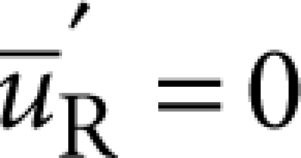 at S) and is based on a decomposition into cylindrical modes for the support, which is approximated by the substrate modelled as an isotropic elastic half-space. The latter approximation is expected to be quantitatively precise for the low-lying flexural resonances when the underetched gap between the suspended structure and the substrate satisfies h<R (where h is the gap height), and the largest resonant wavelength for elastic wave propagation in the substrate is smaller than the relevant length scales characterizing the mounting of the sample (see below). The aforementioned weak-coupling condition, kRd≪1, follows in this case from t≪R. From equation (1), exploiting the fact that the eigenmodes of an elastic half-space are given by straightforward analytical expressions45, we obtain (see Methods section for details of this derivation)
 |
2 |
Here, we introduce the dimensionless functions  ,
,  and the linear stress Fourier components
  with n=0, ±1, ±2, .... The different types of relevant plane-wave modes
 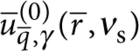 of the half-space45 (that is, longitudinal (l), transverse vertical (t) and surface acoustic waves (s) given that transverse horizontal waves do not contribute) are labelled by γ=l, t, s with cγ, the corresponding speed of sound—as determined by the density ρs, Poisson ratio νs and Young's modulus Es of the substrate. We adopt spherical coordinates for the incident wave vector
  with polar angle θ and cylindrical coordinates for the position
  . The squared displacements
  are given by analytical expressions, that only depend on γ, cosθ and νs24,45, which lead to straightforward integrals for the functions
  detailed in the Methods section.
If one considers low frequency modes that are symmetric with respect to both the x−z and y−z planes so that fz,0≠0 and ωR≪cγ/R ∀γ, one can approximate the series in equation (2) by the n=0 term with the 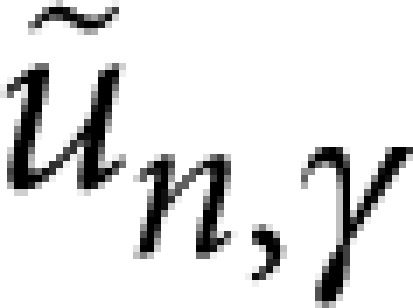 evaluated at
  . For a Poisson ratio νs=1/3, this yields the following approximation
 |
3 |
where fz,0 corresponds to the total force applied on the contact area S. For the typical micromechanical resonators analysed here (see below), this approximation deviates from equation (2) by 20%. Finally, we highlight that it is straightforward to generalize the above to in-plane modes and the rim need not be continuous, as in cases where the resonator volume makes contact with the support at a disjoint set of small areas (for example, a bridge geometry with no undercut).
Free–free design
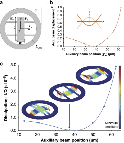
To experimentally verify our solver, we have developed 'free–free' micromechanical resonators consisting of a central plate (resonator) of length L and width w suspended by four auxiliary beams as depicted in Figure 1a. These structures are etched from a high-reflectivity monocrystalline distributed Bragg reflector (DBR)—as described in the Methods section, suited for Fabry–Perot-based optomechanical systems46. The devices used in this study constitute a variant of the previously demonstrated free–free flexural design in which auxiliary beams with widths ws≪w and lengths Ls=λt/4 (where λt is the resonant wavelength for the propagation of torsional waves) placed at the nodes of the central resonator mode provide noise filters to suppress support-induced losses3. A major drawback with the λt/4-beam design is that the resulting auxiliary beam length can be excessive. In fact for the eigenfrequencies investigated in this work, the corresponding beam length (>400 μm at 1.7 MHz) leads to proliferation of low-frequency flexural resonances that compromise the stability of the optical cavity and render mode identification difficult. We circumvent this issue by utilizing instead a reduced length Ls≪λt/4 chosen to avoid spectral overlap between the free–free resonance and flexural resonances of the auxiliary beams.
Figure 1. Mapping out phonon-tunnelling dissipation in a free–free resonator.
(a) Schematic diagram of the resonator geometry. (b) Normalized squared centre of mass displacement of a single auxiliary-beam central-resonator contact calculated via FEM (the inset shows the profile of the free–free mode as approximated by Euler–Bernoulli theory). (c) Simulated dissipation (see equation (2)) as a function of the auxiliary beam's y-coordinate (ya). Values corresponding to eight discrete geometries were calculated here with t=6.67 μm, ws=7 μm, w=42 μm, L=132 μm, R=116 μm and Lund=27 μm—the line is simply a guide for the eye. The FEM-calculated mode shapes correspond to the three extreme examples of the resonator design, from left to right: auxiliary beams near the resonator centre (ya=13 μm), beams near the ideal nodal position (ya=37.4 μm) and beams attached at the ends (ya=62.5 μm). The theoretical clamping loss limit 1/Qth for nodal positioning is always finite with the geometry closest to this position (indicated by the arrow) yielding 1/Qth≈2×10−7.
The free–free design provides an ideal platform to isolate and measure phonon tunnelling dissipation: first, by altering the attachment position of the auxiliary beams, this design allows for a significant variation of geometry, while approximately preserving the frequencies and effective surface-to-volume ratios of the resonators. As these characteristics are kept constant, one can rule out the influence of additional damping mechanisms (specifically those driven by internal losses and surface effects) on the variation in Q and hence isolate support-induced losses in the measured devices. Second, the free–free resonators provide an intuitive illustration of the strong geometric character of the support-induced dissipation. Heuristically, the clamping loss will be proportional to the elastic energy radiated through the auxiliary beams, which should approximately scale as the squared deflection of their contacts with the central resonator (see Fig. 1b,c). Thus, varying the contact position of the auxiliary beams results in a characteristic modulation of the damping rate, which approximately maps out the central resonator mode shape (Fig. 1b). As expected, the minimum-loss design corresponds to the geometry in which the auxiliary beams are attached at the nodes of the fundamental resonance of the central resonator. It is interesting to note that the theoretical clamping loss limit 1/Qth for nodal positioning is always finite as described in Figure 1c. In turn, for generic placement away from the nodal points, one obtains for the improvement in Q with respect to the clamped–clamped configuration the heuristic relation Qf−f/Qc−c∼(w/2ws)2, which assumes that ωR and the effective mass mR are the same for both configurations and ωR lies away from the flexural resonances of the auxilliary beams. This figure of merit can be derived from equation (3), if one uses the approximate scalings  and
and  , which follow from neglecting the undercut, using thin-plate elasticity, and exploiting the fact that ws≪L to analyse the elastic wave propagation in the auxilliary beams24.
Measured dissipation
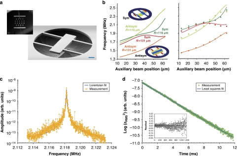
To identify the mechanical modes of our microfabricated resonators (see Figure 2a for an example of a completed device), we compare the optically measured resonator frequencies, as a function of the auxiliary beam position, with the theoretical eigenfrequency variation. The simulated values are generated using the geometric parameters determined via careful analysis of the completed resonators (see Supplementary Method). As can be seen in Figure 2b, in addition to the symmetric free–free resonance, there is also an antisymmetric eigenmode with comparable frequency. We observe no mode coupling between these resonances, which is consistent with the specific mirror symmetries of the structure. The frequencies are accurately reproduced by the FEM simulation, if we allow for frequency offsets that are solely dependent on the mode parity (262 kHz offset for the free–free mode and 89 kHz offset for the antisymmetric mode). We attribute these shifts to a material-related dissipation mechanism involving both surface and bulk contributions (see Supplementary Method for further details).
Figure 2. Characterization of the completed free–free resonators.
(a) Optical micrograph of the 5×5 mm chip containing the batch-fabricated microresonators as well as an electron micrograph highlighting a single suspended structure; the scale bar in this image is 20 μm. (b) Simulated (left) and measured (right) eigenfrequencies as a function of the auxiliary beam y-coordinate. The measured values (discrete points) show excellent agreement with the simulated data set, albeit with a slight offset dependent on the parity of the mode. The fitting lines in the right plot correspond to a mean frequency offset of 262 kHz for the symmetric (sym) free–free modes and 89 kHz for the neighbouring antisymmetric (antisym) modes (inset images show the FEM-derived mode shapes). Lower panels—examples of the fitting techniques utilized for Q-value extraction including: (c) Lorentzian fitting of the free–free resonance (captured on a spectrum analyser) for a device with R=116 μm and ya=29 μm resulting in Q=4.5×10⁴ and (d) ringdown fitting of the same device using linear regression of the natural log of the mean square of the free-ringdown signal captured single-shot with a high-speed oscilloscope yielding Q=4.46×10⁴. The inset includes the residuals to the linear fit showing an excellent agreement with the expected exponential decay.
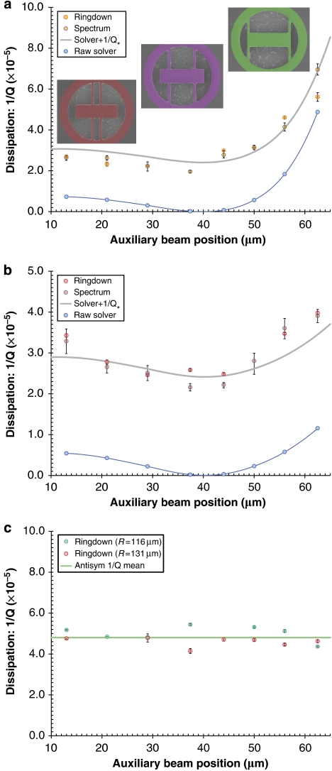
All dissipation measurements have been performed at high vacuum (10−7 mbar) and at cryogenic temperatures (20 K) to suppress fluidic and thermoelastic damping in the devices (Fig. 2c,d). Under these conditions, we record quality factors spanning 1.4×10⁴ to 5.1×10⁴, with the minimum Q corresponding to the free–free mode of devices with an auxiliary position of 62.5 μm and R=116 μm, and with the maximum Q to the geometry closest to nodal positioning (37.4 μm) for the same radius and type of mode (see Fig. 3). For the symmetric mode, we readily observe the expected characteristic modulation in Q as a function of the placement of the auxiliary beams with a relative variation of ΔQexp/Qexp∼260% (∼80%) for R=116 μm (R=131 μm). At the same time, the use of the free–free geometry ensures that the frequency variation is kept small, with a range of Δf/f∼20% (∼10%). In contrast, the Q-values for the antisymmetric mode are nearly constant with Q≈2.1×10⁴ (Fig. 3c). This is expected as the theoretical support-induced loss for this mode is negligible. Additionally, as this resonance involves mainly deformations of the auxiliary beams, its dissipation is not correlated with the mode shapes of the central resonator. The damping of this mode is instead dominated by other sources of dissipation, most likely by the material-related losses that are also responsible for the frequency shifts. Thus, we obtain an independent corroboration that the characteristic Q-variation observed for the free–free mode is indeed induced by the modification of the geometry rather than by the small frequency variation present in the devices.
Figure 3. Compiled dissipation results displaying excellent agreement between the theory and experiment.
(a,b) Comparison of experimental measurements at T=20 K, with theoretical dissipation values for the free–free mode of resonators with measured central dimensions of 132×42 μm and radius R=116 μm and R=131 μm, respectively. Panel (a) includes SEM images of the three extreme designs (for R=116 μm) with overlaid CAD models of the resonator geometry. Both ringdown and spectrally-derived data are included, with values averaged over two nominally identical chips (error bars denote a confidence interval of 99%). We include both raw simulated data as well as fitted data (continuous lines are a guide to the eye) incorporating a constant offset 1/Q*=2.41×10−5. For the effective substrate, we utilize the mechanical properties of Ti, which is the main constituent of the positioning system on which the chips are mounted (ρ=4,540 kg m−3, Es=116 GPa and νs=0.34). (c) Measured dissipation for the antisymmetric (antisym) mode of the same structures exhibiting a lack of geometric dependence.
Discussion
To quantitatively compare the measurements with our numerical predictions, two issues must be considered: (i) our model only captures support-induced losses, although other loss mechanisms may still contribute to the overall damping in the devices and (ii) the parameters for the half-space model of the substrate must be properly chosen. Consideration (i) together with the fact that we have designed sets of resonators for which the frequencies and effective surface-to-volume ratios are kept approximately constant implies that any additional damping mechanism that is relevant at low temperatures and high vacuum, but is insensitive to the variation in geometry, should contribute a constant offset 1/Q* in the measured dissipation 1/Qtot. Consideration (ii) is non-trivial given the long-wavelength nature of the elastic waves radiated into the substrate. For an average resonator frequency of 2.12 MHz, estimates of the maximum wavelength for the freely propagating elastic waves yield a value of 2.5 mm, which largely exceeds the wafer thickness (300±25 μm). Thus, the mechanical material parameters for the substrate should be determined by the properties of the underlying stage and positioning mechanism in the cryostat rather than those of the chip itself. Hence, we assume for the half-space the mechanical properties of polycrystalline commercially pure (grade 2) titanium (see the caption of Figure 3 for more details), of which the bulk of the structure beneath the resonator consists. Taking all of this into account, the theory shows remarkable agreement with the measured dissipation (as shown in Fig 3). It is important to note that the only free parameter used in the model of the free–free mode is a constant offset of 1/Q*=2.41×10−5. Although the exact nature of the corresponding dissipation mechanism is currently unknown, we assume that it arises from material losses in the resonator epi-structure.
It should be noted that most commercially viable resonators operate in a regime where TED dominates, and in some instances, intuitive understandings of the support-induced damping3,8,40 have allowed for its suppression below other limiting damping mechanisms. Nonetheless, if current efforts to minimize TED in such structures at room temperature are successful28, support-induced losses may pose the next challenge for maximizing Q. On the other hand, in fundamental research thrusts employing high vacuum and cryogenic systems, support-induced losses can become a dominant factor7,41. For example, the free–free designs explored here provide a route to minimize support-induced losses for application in optomechanical experiments utilizing the micromechanical resonator as an end mirror in a high-finesse Fabry–Perot cavity46. To gauge the relevance of our 'free–free' micromirror design in this context, it is instructive to compare the fundamental limit at nodal positioning Qth≈5×10⁶ and the maximum measured Q-value of 5.1×10⁴ with the corresponding results for the fundamental flexural mode of a clamped bridge of comparable dimensions. In fact, for the typical dimensions considered, as required for integration in a high-performance Fabry–Pérot cavity, we obtain a theoretical limit Qc−c∼103 in line with previous measurements on monocrystalline DBR optomechanical structures47.
Given the scale-independent nature of support-induced losses, our solver can be applied equally well to nanoscale mechanical devices. We find that for a recent demonstration of a nanomechanical doubly clamped beam coupled to a superconducting qubit at milliKelvin temperatures48, the measured values for the resonator's maximum Q (≈6×10⁴) can be understood solely via the phonon-tunnelling loss model (beam geometry of 0.3×0.18×6 μm; M. LaHaye, private communication), which predicts a Q-value of 5.4×10⁴, in excellent agreement with the experimental value. In addition, the phonon-tunnelling framework is also applicable to prestressed nanoresonators such as Si3N4 strings34 or membranes and has recently been experimentally verified for the latter49.
In conclusion, we have developed an efficient FEM-enabled numerical method for predicting the support-induced dissipation in microscale and nanoscale mechanical resonators. In combination with existing models for other relevant damping channels (for example, fluidic and TED27,28), our 'phonon-tunnelling' solver makes further strides towards accurate prediction of Q. Furthermore, we provide a stringent experimental test of the corresponding theory using resonators engineered to isolate support-induced losses. Our results unambiguously demonstrate that phonon-tunnelling plays a significant role in the mechanical dissipation of these devices and illustrate the strong geometric character of this fundamental damping mechanism. Finally, we note that as the weak-coupling approximation underlying our treatment is more general than the condition of small contact area, our numerical solver can in principle be extended to other relevant scenarios such as phononic-band-gap structures41.
Methods
Numerical calculation of Q-values
To derive equation (2) from equation (1), we adopt for the free elastic half-space45, modelling the decoupled support, a decomposition into eigenmodes  (with n=0, ±1, ±2, ...) that have axial symmetry with respect to z (see Fig. 1). These are related to the plane wave eigenmodes
 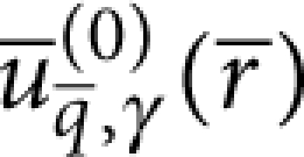 by
by
 |
4 |
where we adopt spherical coordinates for the incident wavevector  (θ=π/2 for γ=s and θ≤π/2 otherwise). We note that for the suspended plate geometry considered, the appropriate resonator mode satisfies
  at the contact S so that we need to evaluate the second term in equation (1).
The thin-plate condition t≪R directly allows us, given the flexural nature of the modes of interest, to neglect stresses at S that are parallel to the substrate, with the possible exception of bending-moment contributions45—this also applies if there are small transverse dimensions comparable to t. However, the bending-moment contributions also become negligible in the limit t/R→0, as can be shown by using: (i) that, given ωR≪cγ/R ∀γ, we can Taylor expand 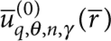 at the origin in the integral over S, (ii) that we can assume relevant stresses to be concentrated around the ends of the auxiliary beams so that the bending moments at S are mostly oriented along y, (iii) the reflection symmetries with respect to the y−z (operator
  ) and x−z (operator
  ) planes and (iv) that, barring interference effects, these bending-moment contributions are at most of relative order24 kRt—here
  is the resonant wavevector for the propagation of flexural waves. Thus, we find that for all mode types other than −+ (antisymmetric (symmetric) with respect to
  (
( )), the correction associated to neglecting the bending moments scales as ΔQ/Q∼(kRt)2, whereas for −+ modes, it scales as ΔQ/Q∼(kRt) (note that L∼R). In turn, we find that the relative error in using equation (1), arising from the weak-coupling approximation, scales in this case as ΔQ/Q∼|ΔωR|/ωR∼|ΔI(ωR)|/2ωR∼(kRt)3, where the phonon-tunnelling-induced frequency shift ΔωR is approximated by
  where I(ω) is the environmental spectrum24.
Hence, we can assume  and neglect the variation of
 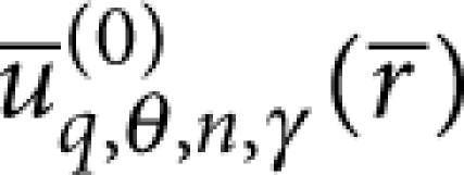 across the thickness t (that is, the z-dependence at S), so that the support modes only enter into equation (1) through
  . To determine the latter, we adopt cylindrical coordinates
  , exploit that reflection at the free surface preserves the tangential component of the wavevector implying
| 5 |
and use the Bessel integral
 |
6 |
Thus from equations (4,5,6), we obtain
 |
7 |
where we have also used that  is independent of ϕ. Subsequently, substitution of equation (7) into equation (1) leads to equation (2) after using that here
 |
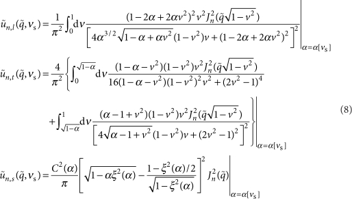
where dγ is the dimensionality (that is, dγ=3 for γ≠s and dγ=2 for γ=s), performing the substitution ω=cγq (for each γ), and integrating over ω. Finally, substitutionof the explicit expressions for the plane wave eigenmodes 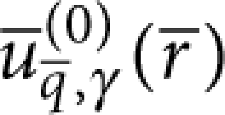 (see for example Appendix A in ref. 24) and ν=cosθ into the definition of
  allows us to obtain:
 |
9 |
where we use the ratio α≡(ct/cl)2=(1−2νs)/2(1−νs) for the supports' material (νs is the corresponding Poisson ratio). In turn, ξ(α) is the ratio of the propagation velocity of surface waves to ct, which is always less than unity45, and
 |
10 |
The sum in equation (2) can be reduced to a sum over n≥0 by noting that J−n(x)=(−1)nJn(x) and that as the resonator mode is real, the linear stress Fourier components satisfy  . Furthermore, the length of the central resonator L is comparable to the radius R, and we focus on low-lying resonances of the suspended structure so that the aforementioned condition ωR≪cγ/R ∀γ is always satisfied. This implies
  for m>n and
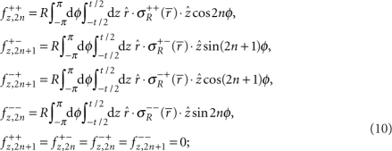
  , which can be understood by considering the behaviour of the Bessel functions for small arguments. Thus, we find that in equation (2), the sum over the index n is dominated by the first non-vanishing term as determined by the reflection symmetries
 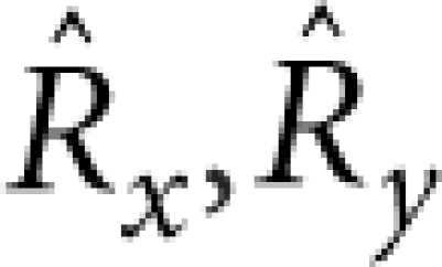 . The latter also imply (n=0, 1, 2, ...):
 |
11 |
where the resonator mode of type α,β satisfies  and
and  . To efficiently extract the above from the FEM simulation, we convert them into volume integrals using an adequate Gaussian weight so that, for example, for a fully symmetric mode, we have
 |
12 |
where we again use cylindrical coordinates and V denotes the resonator volume. In addition, we exploit that the reflection symmetries naturally allow to perform the FEM simulation on a single quadrant. Thus, numerical evaluation can be conveniently performed using a fixed a* and a mesh size M such that (V/4 M)1/3<a*≪t. We have checked the convergence and estimate the numerical error to be of order 5%.
Numerical simulations of the resonator mode are performed with the aid of COMSOL multiphysics. Accurate three-dimensional CAD models representing the resonator geometry are generated using Solidworks (matched with high-quality scanning electron microscope images as described in Supplementary Method), and the bidirectional interface between the two programs is exploited to perform a parametric sweep of the auxiliary beam contact position for determining the pertinent information about the relevant mode, namely its eigenfrequency, linear stress Fourier components fz,n and normalization constant. In this instance, a single CAD file is used with a global variable incorporated to control the lateral position of the auxiliary beams with respect to the centre of the central resonator. We use for the mechanical properties of our single-crystal resonators an anisotropic material model incorporating the elastic stiffness matrix for the epitaxial structure as obtained from a weighted average between the relative content of GaAs and AlAs (46.37% GaAs/53.63% AlAs). The corresponding parameters are: C11=119.6 GPa, C12=55.5 GPa, C44=59.1 GPa and ρR=4,483 kg m−3. The resonator axes are aligned along 〈100〉 (zinc-blende structure). Note that we ignore the 6° misorientation of the germanium substrate, as we have checked that it has a negligible impact (error of 0.3%) on the simulated frequency response of the resonators. Finally, as a non-trivial check, we have applied our numerical method to bridge geometries with no undercut for which a simple analytic expression is valid in the limit of large aspect ratio (see Supplementary Method).
Epitaxial material structure and resonator fabrication procedure
The layer structure for our high reflectivity resonators consists of 40.5 periods of alternating quarter-wave GaAs (high index) and AlAs (low index) grown lattice-matched to an off-cut monocrystalline germanium substrate. The ideal total thickness of the heterostructure is 6,857.6 nm, with individual layer thicknesses of 77.6 and 91.9 nm for the GaAs and AlAs, respectively, yielding a nominal peak reflectivity at 1,064 nm, as with our previous optomechanics experiments47. With this design, the germanium substrate enables the use of a high-selectivity gas-phase etching procedure, based on the noble-gas halide XeF2, to rapidly and selectively undercut the underlying germanium substrate. Thus, we realize a free-standing epitaxial Bragg mirror via a simple and fast-turnaround fabrication procedure. The details of both the epitaxial material design and microfabrication procedure are covered in ref. 50.
Measurement technique
To characterize the frequency response of our microresonators, we utilize a custom-built optical fibre interferometer featuring a continuous flow 4He cryostat as the sample chamber51. High-sensitivity displacement resolution is achieved in this system via optical homodyne interferometry. Cryogenic testing of these devices is necessitated because of the limitations imposed by TED at room temperature. Estimation of the magnitude of TED is possible using the analytical and finite element models developed previously26,27,28, which predict a Q-value of ∼4,000 for the current DBR composition and thickness at 1.8 MHz and 300 K—consistent with performed measurements. To avoid TED, our cryostat enables interrogation down to 20 K (resulting in an estimated TED limited Q of 9.9×10⁸); the minimum temperature is currently limited by the large view-port above the sample stage. Additionally, this system is capable of vacuum levels down to 2.5×10⁻⁷ mbar at cryogenic temperatures, removing any additional damping induced by fluidic or squeeze film effects29,30,31. The eigenmodes of the resonator are excited by driving a high-frequency (10 MHz) piezo disc soldered to a copper stage in thermal contact with the cold finger. For spectral characterization, the piezo disc is driven with white noise and the resonator frequency response is recorded on a spectrum analyser. For the free-ringdown measurements, the decay of a resonantly excited device is recorded in a single shot on a high-speed oscilloscope (see Supplementary Method for further details).
Author contributions
G.D.C. and I.W.R. designed the experiment (with the use of the free–free design suggested by I.W.R.) and developed the numerical solver. G.D.C. fabricated the microresonators. M.R.V. and G.D.C. designed and constructed the cryogenic optical-fiber interferometer. K.W. and G.D.C. measured the resonator frequency response and extracted the dissipation values. M.A. supervised the research effort. All authors contributed to the writing of the manuscript.
Additional information
How to cite this article: Cole, G. D. et al. Phonon-tunnelling dissipation in mechanical resonators. Nat. Commun. 2:231 doi: 10.1038/ncomms1212 (2011).
Supplementary Material
Supplementary Figures S1-S2, Supplementary Methods and Supplementary Reference.
Acknowledgments
G.D.C. is a recipient of a Marie Curie Fellowship of the European Commission (EC). Additional financial support is provided by the EC (projects MINOS, IQOS, QESSENCE), the Austrian Science Fund (projects START, L426 and SFB FoQuS) and the European Research Council (ERC StG QOM). Microfabrication was carried out at the Zentrum für Mikro- und Nanostrukturen (ZMNS) of the Technische Universität Wien, while the heterostructure was grown by Yu Bai at MIT. G.D.C. gratefully acknowledges Stephan Puchegger and Markus Schinnerl for assistance with scanning electron microscopy and focused ion beam milling. I.W.R. acknowledges financial support via the Nanosystems Initiative Munich, K.W. via the Austrian Research Promotion Agency (FFG) and M.R.V. via the FWF Doctoral Programme (CoQuS).
References
- Craighead H. G. Nanoelectromechanical systems. Science 290, 1532–1535 (2000). [DOI] [PubMed] [Google Scholar]
- Ekinci K. L. & Roukes M. L. Nanoelectromechanical systems. Rev. Sci. Instrum. 76, 061101 (2005). [Google Scholar]
- Wang K., Wong A.- C. & Nguyen C. T.- C. VHF free-free beam high-Q micromechanical resonators. J. Microelectromech. Syst. 9, 347–360 (2000). [Google Scholar]
- Cleland A. N. Foundations of Nanomechanics (Springer, 2003). [Google Scholar]
- Bindel D. S. & Govindjee S. Elastic PMLs for resonator anchor loss simulation. Int. J. Numer. Methods Eng. 64, 789–818 (2005). [Google Scholar]
- Judge J. A., Photiadis D. M., Vignola J. F., Houston B. H. & Jarzynski J. Attachment loss of micromechanical and nanomechanical resonators in the limits of thick and thin support structures. J. Appl. Phys. 101, 013521 (2007). [Google Scholar]
- Anetsberger G., Riviere R., Schliesser A., Arcizet O. & Kippenberg T. J. Ultralow-dissipation optomechanical resonators on a chip. Nature Photonics 2, 627–633 (2008). [Google Scholar]
- Clark J., Hsu W.- T., Abdelmoneum M. & Nguyen C.- C. High-Q UHF micromechanical radial-contour mode disk resonators. J. Microelectromech. Syst. 14, 1298–1310 (2005). [Google Scholar]
- Lutz M. et al. MEMS oscillators for high volume commercial applications. in Proc. Transducers, Solid-State Sensors, Actuators and Microsyst (2007). 14th Int. Conf. [Google Scholar]
- Sidles J. A. et al. Magnetic resonance force microscopy. Rev. Mod. Phys. 67, 249–265 (1995). [Google Scholar]
- Rugar D., Budakian R., Mamin H. J. & Chui B. W. Single spin detection by magnetic resonance force microscopy. Nature 430, 329–332 (2004). [DOI] [PubMed] [Google Scholar]
- Degen C. L., Poggio M., Mamin H. J., Rettner C. T. & Rugar D. Nanoscale magnetic resonance imaging. Proc. Natl Acad. Sci. USA 106, 1313–1317 (2009). [DOI] [PMC free article] [PubMed] [Google Scholar]
- Li M., Tang H. X. & Roukes M. L. Ultra-sensitive nems-based cantilevers for sensing, scanned probe and very high-frequency applications. Nat. Nanotechnol. 2, 114–120 (2007). [DOI] [PubMed] [Google Scholar]
- Jensen K., Kim K. & Zettl A. An atomic-resolution nanomechanical mass sensor. Nat. Nanotechnol. 3, 533–537 (2008). [DOI] [PubMed] [Google Scholar]
- Naik A. K., Hanay M. S., Hiebert W. K., Feng X. L. & Roukes M. L. Towards single-molecule nanomechanical mass spectrometry. Nat. Nanotechnol. 4, 445–450 (2009). [DOI] [PMC free article] [PubMed] [Google Scholar]
- Armour A. D., Blencowe M. P. & Schwab K. C. Entanglement and decoherence of a micromechanical resonator via coupling to a cooper-pair box. Phys. Rev. Lett. 88, 148301 (2002). [DOI] [PubMed] [Google Scholar]
- Marshall W., Simon C., Penrose R. & Bouwmeester D. Towards quantum superpositions of a mirror. Phys. Rev. Lett. 91, 130401 (2003). [DOI] [PubMed] [Google Scholar]
- Blencowe M. Quantum electromechanical systems. Phys. Rep. 395, 159–222 (2004). [Google Scholar]
- Schwab K. C. & Roukes M. L. Putting mechanics into quantum mechanics. Phys. Today 58, 36–42 (2005). [Google Scholar]
- Kippenberg T. J. & Vahala K. J. Cavity optomechanics: back-action at the mesoscale. Science 321, 1172–1176 (2008). [DOI] [PubMed] [Google Scholar]
- Aspelmeyer M. & Zeilinger A. A quantum renaissance. Phys. World 21, 22–28 (2008). [Google Scholar]
- Aspelmeyer M. & Schwab K. Focus on mechanical systems at the quantum limit. New J. Phys. 10, 095001 (2008). [Google Scholar]
- O'Connell A. D. et al. Quantum ground state and single-phonon control of a mechanical resonator. Nature 464, 697–703 (2010). [DOI] [PubMed] [Google Scholar]
- Wilson-Rae I. Intrinsic dissipation in nanomechanical resonators due to phonon tunneling. Phys. Rev. B 77, 245418 (2008). [Google Scholar]
- Kiselev A. A. & Iafrate G. J. Phonon dynamics and phonon assisted losses in Euler-Bernoulli nanobeams. Phys. Rev. B 77, 205436 (2008). [Google Scholar]
- Zener C. Internal friction in solids. I. Theory of internal friction in reeds. Phys. Rev. 52, 230–235 (1937). [Google Scholar]
- Lifshitz R. & Roukes M. L. Thermoelastic damping in micro- and nanomechanical systems. Phys. Rev. B 61, 5600–5609 (2000). [Google Scholar]
- Duwel A., Candler R. N., Kenny T. W. & Varghese M. Engineering MEMS resonators with low thermoelastic damping. J. Microelectromech. Syst. 15, 1437–1445 (2006). [Google Scholar]
- Vignola J. F. et al. Effect of viscous loss on mechanical resonators designed for mass detection. Appl. Phys. Lett. 88, 041921 (2006). [Google Scholar]
- Karabacak D. M., Yakhot V. & Ekinci K. L. High-frequency nanofluidics: an experimental study using nanomechanical resonators. Phys. Rev. Lett. 98, 254505 (2007). [DOI] [PubMed] [Google Scholar]
- Verbridge S. S., Craighead H. G. & Parpia J. M. A megahertz nanomechanical resonator with room temperature quality factor over a million. Appl. Phys. Lett. 92, 013112 (2008). [Google Scholar]
- Yasumura K. et al. Quality factors in micron- and submicron-thick cantilevers. J. Microelectromech. Syst. 9, 117–125 (2000). [Google Scholar]
- Mohanty P. et al. Intrinsic dissipation in high-frequency micromechanical resonators. Phys. Rev. B 66, 085416 (2002). [Google Scholar]
- Verbridge S. S. et al. High quality factor resonance at room temperature with nanostrings under high tensile stress. J. Appl. Phys. 99, 124304 (2006). [Google Scholar]
- Southworth D. R. et al. Stress and silicon nitride: a crack in the universal dissipation of glasses. Phys. Rev. Lett. 102, 225503 (2009). [DOI] [PubMed] [Google Scholar]
- Venkatesan A. et al. Dissipation due to tunneling two-level systems in gold nanomechanical resonators. Phys. Rev. B 81, 073410 (2010). [Google Scholar]
- Unterreithmeier Q. P., Faust T. & Kotthaus J. P. Damping of nanomechanical resonators. Phys. Rev. Lett. 105, 027205 (2010). [DOI] [PubMed] [Google Scholar]
- Seoánez C., Guinea F. & Castro Neto A. H. Surface dissipation in nanoelectromechanical systems: unified description with the standard tunneling model and effects of metallic electrodes. Phys. Rev. B 77, 125107 (2008). [Google Scholar]
- Remus L. G., Blencowe M. P. & Tanaka Y. Damping and decoherence of a nanomechanical resonator due to a few two-level systems. Phys. Rev. B 80, 174103 (2009). [Google Scholar]
- Mattila T. et al. A 12 MHz micromechanical bulk acoustic mode oscillator. Sens. Actuators A Phys. 101, 1–9 (2002). [Google Scholar]
- Eichenfield M., Chan J., Camacho R. M., Vahala K. J. & Painter O. Optomechanical crystals. Nature 462, 78–82 (2009). [DOI] [PubMed] [Google Scholar]
- Cross M. C. & Lifshitz R. Elastic wave transmission at an abrupt junction in a thin plate with application to heat transport and vibrations in mesoscopic systems. Phys. Rev. B 64, 085324 (2001). [Google Scholar]
- Park Y.- H. & Park K. C. High-fidelity modeling of MEMS resonators-part I: anchor loss mechanisms through substrate. J. Microelectromech. Syst. 13, 238–247 (2004). [Google Scholar]
- Photiadis D. M. & Judge J. A. Attachment losses of high Q oscillators. Appl. Phys. Lett. 85, 482–484 (2004). [Google Scholar]
- Graff K. F. Wave Motion in Elastic Solids (Dover, 1991). [Google Scholar]
- Gröblacher S. et al. Demonstration of an ultracold micro-optomechanical oscillator in a cryogenic cavity. Nat. Phys. 5, 485–488 (2009). [Google Scholar]
- Cole G. D., Gröblacher S., Gugler K., Gigan S. & Aspelmeyer M. Monocrystalline Al(x)Ga(1-x)As heterostructures for high-reflectivity high-q micromechanical resonators in the megahertz regime. Appl. Phys. Lett. 92, 261108 (2008). [Google Scholar]
- LaHaye M. D., Suh J., Echternach P. M., Schwab K. C. & Roukes M. L. Nanomechanical measurements of a superconducting qubit. Nature 459, 960–964 (2009). [DOI] [PubMed] [Google Scholar]
- Wilson-Rae I. et al. High-Q nanomechanics via destructive interference of elastic waves. Phys. Rev. Lett. 106, 047205 (2011). [DOI] [PubMed] [Google Scholar]
- Cole G. D., Bai Y., Aspelmeyer M. & Fitzgerald E. A. Free-standing Al(x)Ga(1-x)As heterostructures by gas-phase etching of germanium. Appl. Phys. Lett. 96, 261102 (2010). [Google Scholar]
- Cole G. D. et al. Megahertz monocrystalline optomechanical resonators with minimal dissipation in Proc. IEEE Micro Electro Mechanical Syst. 847–850 (2010). 23rd Int. Conf. [Google Scholar]
Associated Data
This section collects any data citations, data availability statements, or supplementary materials included in this article.
Supplementary Materials
Supplementary Figures S1-S2, Supplementary Methods and Supplementary Reference.


