Abstract
The determination of a cancer free margin I organs is a difficult and time consuming process, with an unmet need for rapid determination of tumor margin at surgery. In this paper, we report the design, fabrication and testing of a novel miniaturized optical sensor probe with “side-viewing” capability. Its unprecedented small size, unique “side-viewing” capability and high optical transmission efficiency enable the agile maneuvering and efficient data collection even in the narrow cavities inside the human body. The sensor probe consists of four micromachined substrates with optical fibers for oblique light incidence and collection of spatially resolved diffuse reflectance from the contacted tissues. The optical sensor probe has been used to conduct the oblique incidence diffuse reflectance spectroscopy (OIDRS) on a human pancreatic specimen. Based on the measurement results, the margin of the malignant tumor has been successfully determined optically, which matches well with the histological results.
Index Terms: Diffuse reflectance, oblique incidence, spectroscopy, micro optical probe, tumor margin, pancreatic cancer
I. Introduction
In surgical treatments of malignant tumors, the effectiveness of the treatment procedures largely depends on the ability to completely and precisely remove the malignant tumor tissue. However, in the operation room (OR), determining a safe margin for malignant tumor removal (especially those without a clear boundary, such as pancreatic tumor) has been a challenging and time-consuming “guesswork” for the surgeons. Generally, the tissue in the suspicious regions is first removed and the histological samples are prepared and analyzed. Based on the results of the histology, the next round of tissue removal is planned and performed. A complete surgery would require multiple cycles of tissue removal and analysis, which results in an extremely long procedure. To address this issue, new sensing and imaging tools are necessary to enable fast, accurate and robust tumor margin detection in the OR.
Oblique incidence diffuse reflectance spectroscopy (OIDRS) is a unique optical spectroscopic method, which utilizes a special fiber optic sensor probe (coupled with a data acquisition system) to robustly and accurately measuring the diffuse reflectance of inhomogeneous media (e.g., biological tissues) in contact [1]. Both the optical absorption and scattering properties of the inhomogeneous media can be readily extracted from the measured diffuse reflectance spectra. Recent studies have shown that the optical absorption and scattering properties of human tissues are closely linked to certain critical physiological signatures of their states of malignancy [2-6]. Therefore, OIDRS could provide a fast and minimally-invasive approach to differentiate the malignant tissue from the benign one with high sensitivity and specificity [7, 8]. To apply OIDRS for malignant tumor margin detection, miniaturized fiber optic probes suitable for inner-body operations is needed.
In this paper, we report the development and application of a new micro OIDRS probe. The extremely small form factor, high optical transmission efficiency, and side-viewing capability make it well suitable for in vivo OIDRS measurements inside the human body under typical OR settings. The new OIDRS probe has been used to conduct diffuse-reflectance measurements on human pancreatic specimens. Based on the measurement results, the margin between the malignant tissues and the benign ones has been successfully identified, which matches well with the histological readings.
II. Oblique Incidence Diffuse Reflectance Spectroscopy
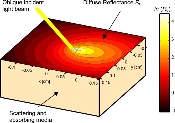
As shown in Fig. 1, when light is incident on the surface of an inhomogeneous medium (e.g., human tissue), certain portion of the incident light will be directly reflected (specular reflectance). The remaining portion of the incident light will transmit into and interacts with the medium. After undergoing multiple times of scattering and absorption, part of the transmitted light will be scattered back and forms the diffuse reflectance.
Fig. 1.
The absorption and scattering of obliquely-incident light in an inhomogeneous medium.
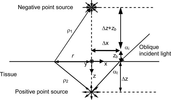
According to the diffusion theory, the spatially-resolved steady-state diffuse reflectance for an oblique incidence of a particular wavelength can be calculated by [9].
| (1) |
where ρ1 and ρ2 are the distances between the source point and the observation point on the surface of the medium (Fig. 2). Δz is the distance between the virtual boundary and the medium depth, and zb is the distance between the virtual boundary and the surface of the sample. The distance from the point of incidence to the positive point source ds is equal to 3D, where D is the diffusion coefficient. For oblique incidence, D = (3(0.35 μa + μs’))-1, where μa is the absorption coefficient and μs’ is the reduced scattering coefficient. The effective attenuation coefficient μeff = (μa/D)1/2. The shift of the point sources in the x direction Δx = sin(αt)/(3(0.35 μa + μs’)), and αt is the angle of light transmission into the tissue. The absorption (μa) and reduced scattering (μs’) coefficients can be calculated by
| (2) |
| (3) |
Fig. 2.
Schematic of the diffusion theory model for oblique incidence.
It should be noted that the diffusion theory assumes that the reduced scattering coefficient is much larger than the absorption. The source and detector must also be separated in space so that the light is diffusive when it reaches the detector. When the distance between the source and the detectors is comparable to the transport mean free path (~1 mm) in the tissue, diffusion theory does not apply. In this case, Monte Carlo simulation can be applied for the extraction of absorption and reduced scattering coefficients from the diffuse reflectance [10].
The optical absorption of the human tissue is mainly affected by the concentration of hemoglobin, concentration of oxygenated and deoxygenated hemoglobin, and oxygen saturation of hemoglobin. These parameters are important because they are believed to be related to the disease state of lesions [11-13]. Other forms of hemoglobin such as methemoglobin and carboxyhemoglobin are normally present in small concentrations, except in some very special pathologic conditions. On the other hand, the major optical scatterer in the human tissue is the cell nuclei. It has been shown that the diameter of cell nuclei would increase with its degree of dysplaticity in different lesions [14]. Therefore, the close relationship between the optical absorption and scattering properties of human tissues and the hallmarks of their states of malignancy forms the physiological foundation for the clinical application of OIDRS in cancer detection.
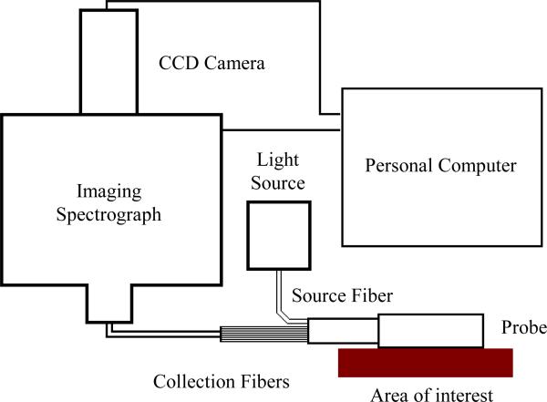
To enable robust diffuse reflectance measurements in a clinical setting, we have built a prototype OIDRS system (Fig. 3) [7]. It consists of a white light source (halogen lamp), a fiber-optic OIDRS probe and a data acquisition interface. The OIDRS probe consists of one or multiple oblique-incidence source fibers and a liner array of collection fibers. The data acquisition interface includes an imaging spectrograph, a CCD camera, and a personal computer. During an OIDRS measurement, the OIDRS probe is touched onto the tissue surface of interest. White light is obliquely incident onto the tissue surface through the source fiber, the spatial distribution of the diffuse reflectance (R(x)) is captured by the collection fibers and couple to the multi-track input of the imaging spectrograph. The imaging spectrograph separates out all the wavelength components from each collection fiber and projects the spectral image into the CCD camera. Before each spectral image was stored in a personal computer, a background subtraction was performed to remove the dark room camera system noise.
Fig. 3.
Schematic of the OIDRS system.
III. Probe Design & Fabrication
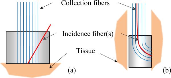
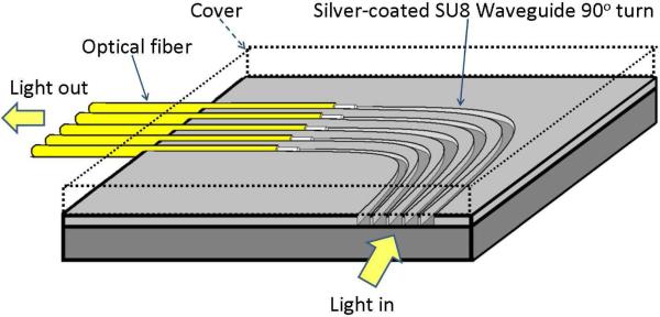
To conduct an OIDRS measurement, it is necessary to deliver light of particular wavelength at a desirable oblique incidence angle and also collect the one-dimensional linear distribution of the diffuse reflectance R(x). On the tissue surfaces with easy accessibility (e.g., skin), the OIDRS measurement can be conducted with a conventional “front-viewing” optical probe, consisting of a bundle of straight optical fibers (Fig. 4a) [1]. However, the “front-viewing” configuration poses a challenge for the in-vivo measurements inside the human body. This is because most internal organs consist of long and narrow tubular cavities (e.g., the gastrointestinal (GI) tract, blood vessels, and air pathways). To ensure effective in-vivo measurement, a miniaturized “side viewing” configuration will be necessary (Fig. 4b). However, obtaining both probe miniaturization and “side-viewing” capability requires dense placement and sharp bending of optical fibers, which would cause excessive light loss, cross-talk or even mechanical fracture of the optic fibers.
Fig. 4.
Schematic of micro OIDRS probes for in-vivo optical characterization of human tissues: (a) front-viewing configuration and (b) side-viewing configuration.
To address this issue, we have investigated the concept of using microfabricated polymer waveguides to enable the “side viewing” function [15]. As shown in Fig. 5, depending on the actual probe design, an array of curved polymer waveguides was first fabricated on a flat substrate. The top and bottom surfaces and the two sidewalls of the curved polymer waveguides were coated with highly reflective metal layers to prevent possible light leakage and cross-talk. In our previous work, SU-8 polymer (Microchem, Inc., Newton, MA) was selected as the structural material of the waveguides. Compared with many other polymer materials, the advantage of SU-8 is that it can easily form relatively thick layers (from 100 μm to 500 μm) and can be directly patterned using photolithography without involving expensive microfabrication equipment and complex process steps. To interface the waveguides to the data acquisition interface, a second substrate with a group of parallel V-groves was used to align the straight interconnection fiber bundles with exactly same pitch of that of the SU-8 waveguides. However, the “two-chip” design poses some challenges to the probe fabrication and assembly.
Fig. 5.
Schematic design of the “side-viewing” OIDRS probe.
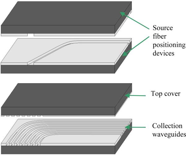
Due to their small size, it is a tedious and time-consuming process to achieve good alignment (and thus light coupling) between the SU-8 waveguides and the interconnection fibers. Moreover, the light from the output terminals of the SU-8 waveguides is usually diffusive. To avoid possible cross-talk between two adjacent collection channels, the spacing between two adjacent waveguides cannot be made too small, which limits ultimate probe miniaturization, which otherwise would be required (for OIDRS measurements in small vessels and ducts (e.g. pancreatic duct) inside the human body). To address the above issues, we came up with a new “one-chip” OIDRS probe design. Instead of directly using SU-8 as the waveguide material, parallel micro channels are formed in the SU-8 layer, which serve as both the optical waveguide and the alignment structures for the interconnection fibers (Fig. 5). The “one-chip” probe design brings several advantages. First, the interconnection fibers are automatically aligned with the waveguides to ensure good coupling, which greatly facilitates the probe fabrication and assembly. Second, because the transmitted light is well confined in each channel, the cross-talk between two adjacent channels is largely avoided. As a result, the spacing between two adjacent channels can be minimized to enable for ultimate probe miniaturization. Third, the channels can be left unfilled to form air-core waveguide or can be filled with optical epoxies (with superior optical transmittance than SU-8) to enhance the optical transmission efficiency. Especially, the air waveguide is ideal for applications where optical characterization over a wide spectrum (e.g., from ultraviolet to infrared) is needed. On the other hand, filling the channels with optical epoxy can improve the coupling between the interconnection fiber and the waveguide, thus boosting the performance in the visible range (while at the expense of blocking other wavelengths). For comparison, the optical transmission efficiency of two curve waveguides (one filled with SU-8 and the other one filled with EPO-TEK 301 optical epoxy (Epoxy Technology Inc., Billerica MA), was calculated with a rays trace simulation, which shows an optical transmission efficiency of 66% and 9 %, respectively (Fig. 6).
Fig. 6.
Simulation of the light distribution in a silver coated EPO-TEK 301 waveguide with a 700 μm bending radius and coupled to an 100 μm optical fiber with a numerical aperture (NA) of 0.22.
Fig. 7a shows the detailed structure of the “side-viewing” OIDRS probe based on the new “one-chip” design. It consists of four pieces of silicon substrates containing microfabricated SU-8 channels. The first and second substrates have one open channel (~ 120 μm deep) on each of them, forming a mirrored pair. The width of the channels is ~ 240 μm. When being stacked together, they create a close channel with a cross-section area of ~ 240 × 240 μm2, which serves as the waveguide and positioning device for the 200-μm source fiber. To form and interface the collection channels, a group of curved SU-8 channels (~ 140 μm deep) are fabricated onto the fourth substrate, while the third substrate serves as the top cover with SU-8 patterns (~ 5 μm thick), which are complementary with the channels on the fourth substrate. When the two substrates are stacked together, tightly closed channels can be formed, which serve as the waveguide and positioning device for the interconnection fibers. Compared with a flat cover substrate, the “textured” substrate is advantageous in preventing the possible light leakage and inter-channel cross-talk.
Fig. 7.
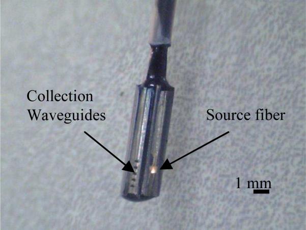
(a) OIDRS probe assembly and (b) Complete OIDRS probe.
To minimize the loss of the waveguides, all the horizontal and vertical surfaces of the SU-8 structures were coated with a thin layer of silver (~ 300 nm thick) using electron-beam evaporation. To ensure a uniform coating, the substrates were mounted onto a platen at ± 45° with respect to the source, which was constantly rotating during the entire deposition process. The assembly of the OIDRS probe was essentially stacking and aligning the four silicon substrates with the source and interconnection fibers placed in the aligning SU-8 channels. To securely bond the silicon substrates together, optical epoxy (EPO-TEK 301) was applied onto the surfaces of the adjacent substrates. The optical epoxy also serves as the filler of the SU-8 channels. The proximal ends of the all the optical fibers are placed in SMA connectors to enable interfacing with the OIDRS system. Fig. 7b shows a zoom-in picture of a completed “side-viewing” OIDRS probe based on the “one-chip” design. This probe has one 45° oblique incidence channel and seven collection channels. The overall size of the probe tip is 8 × 2.5 × 2 mm3, which is small enough to make it suitable for different endoscopic applications.
IV. Testing Results
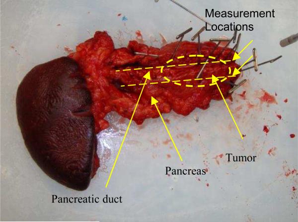
The OIDRS system was used to conduct ex-vivo measurement of a freshly excised human pancreas specimen with a malignant tumor (Fig 8). Before the OIDRS measurement, the whole experimental setup was calibrated using a standard liquid phantom with trypan blue dye as the absorbers and polystyrene microspheres as the scattering elements [16]. The absorption coefficient spectra of trypan blue were measured by collimated transmission before mixing it with the polystyrene micro-spheres, which are added as scattering elements. The expected values of the absorption and reduced scattering coefficients of the liquid reference solution can be varied by controlling the concentration of absorbing and scattering chemicals. These values are then used to calibrate the measurements from the OIDRS probe. To test the feasibility of using OIDRS for tumor margin detection, a series of measurements were performed along the opened pancreatic duct (where the pancreatic cancers usually start to develop), with a 1-cm interval. The probe was place on top of the area of interest by gently touching the sample. Several measurements were conducted at each location to average the diffuse reflectance data, which helps to improve the uniformity and consistency of the data collection.
Fig. 8.
Pancreas specimen with a malignant tumor
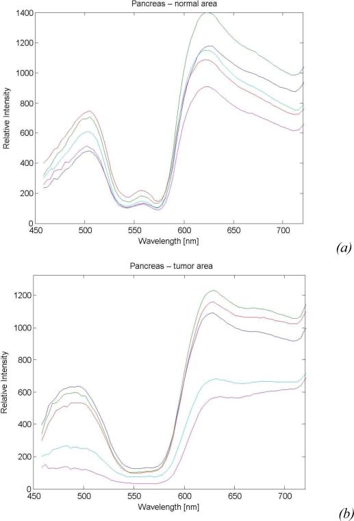
Fig. 9a and 9b show the representative diffuse reflectance spectra (five channels) measured from both the normal and the malignant regions in the pancreas specimen, which clearly show the difference in their optical signatures. To achieve a better understanding of the physiological origin of these differences, the absorption and scattering parameters were extracted from the measured diffuse reflectance spectra. In human tissues, hemoglobin is the major absorber within the visible spectrum.
Fig. 9.
Sample diffuse reflectance spectra of the pancreas specimen collected from: (a) Normal tissue and (b) Malignant tissue.
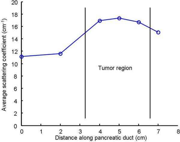
As shown in Fig. 8, due to the extensive bleeding caused by the surgical excision, the concentration of the hemoglobin and thus the absorption parameters of both the normal and malignant regions in the pancreatic specimen must have changed significantly from their original values. However, the scattering parameter, which is mainly due to the cell density and the size of the cell nuclei, will not be affected by the bleeding. Previous studies have shown that malignant tissues usually manifest higher optical scattering due to increased cell density and enlarged cell nuclei [14]. Therefore, the relative value of the scattering parameter could serve as a good indicator to differentiate the malignant tissues from the normal ones. Fig. 9 shows the extracted scattering parameters for different locations along the pancreatic duct, which clearly indicate the existence and location of the tumor region. This result matches well with the histological reading of the pancreas specimen.
Conclusions
A new miniaturized OIDRS optical sensor probe with side-viewing capability has been successfully developed utilizing micromachining technology. The use of an innovative curved optical glue core waveguide structure allows the 90° light bending with minimum loss and crosstalk. It enables higher transmission efficiency and wider wavelength range than the curved polymer waveguide we previously demonstrated. Our preliminary results show that the probe, combined with OIDRS can provide both functional and structural information of tissue malignancy and thus can be a useful tool for rapidly determining a safe margin for the surgical treatment of cancers.
Fig. 10.
Average scattering coefficient along the pancreatic duct.
Acknowledgments
This work was supported by National Institute of Health grant R01 CA106728.
Contributor Information
A. Garcia-Uribe, Department of Biomedical Engineering, Washington University in St. Louis, St. Louis, MO 63130 USA (aguribe@gmail.com)
C.-C. Chang, Department of Electrical and Computer Engineering, Texas A&M University, College Station, TX 77843 USA
M. K. Yapici, Department of Electrical and Computer Engineering, Texas A&M University, College Station, TX 77843 USA
J. Zou, Department of Electrical and Computer Engineering, Texas A&M University, College Station, TX 77843 USA
B. Banerjee, University Medical Center, University of Arizona, Tucson, AZ 85724 USA
J. Kuczynski, University Medical Center, University of Arizona, Tucson, AZ 85724 USA
E. Ong, University Medical Center, University of Arizona, Tucson, AZ 85724 USA
E. S. Marner, University Medical Center, University of Arizona, Tucson, AZ 85724 USA
L. V. Wang, Department of Biomedical Engineering, Washington University in St. Louis, St. Louis, MO 63130 USA
References
- 1.Garcia-Uribe A, Balareddy KC, Zou J, Wang LV. Micromachined Fiber Optical Sensor for In-Vivo Measurement of Optical Properties of Human Skin. IEEE Sensors Journal. 2008;8(10):1698–1703. [Google Scholar]
- 2.Bargo PR, Pral. SA, Goodell TT, Sleven RA, Koval G, Blair G, Jacques SL. In vivo determination of optical properties of normal and tumor tissue with white light reflectance and an empirical light transport model during endoscopy. Journal of Biomedical Optics. 2005;10(3) doi: 10.1117/1.1921907. [DOI] [PubMed] [Google Scholar]
- 3.Zhu TC, Finlay JC, Hahn SM. Determination of the distribution of light, optical properties, drug concentration, and tissue oxygenation in-vivo in human prostate during motexafin lutetium-mediated photodynamic therapy. Journal of Photochemistry and Photobiology B. 2005;79(3):1, 231–241. doi: 10.1016/j.jphotobiol.2004.09.013. [DOI] [PMC free article] [PubMed] [Google Scholar]
- 4.Troy TL, Page DL, Sevick-Muraca EM. Optical properties of normal and diseased breast tissues: prognosis for optical mammography. Journal of Biomedical Optics. 1996;1(3):342–355. doi: 10.1117/12.239905. [DOI] [PubMed] [Google Scholar]
- 5.Georgakoudi I, Jacobson BC, Van Dam J, Backman V, Wallace MB, Muller MG, Zhang Q, Badizadegan K, Sun D, Thomas GA, Perelman LT, Feld MS. “Fluorescence, reflectance, and “light-scattering spectroscopy for evaluating dysplasia in patients with Barrett's esophagus. Gastroenterology. 2001;120(7):1620–1629. doi: 10.1053/gast.2001.24842. [DOI] [PubMed] [Google Scholar]
- 6.Mirabal YN, Chang SK, Atkinson EN, Malpica A, Follen M, Richards-Kortum R. Reflectance spectroscopy for in vivo detection of cervical precancer. Journal of Biomedical Optics. 2002;7(4):587–594. doi: 10.1117/1.1502675. [DOI] [PubMed] [Google Scholar]
- 7.Garcia-Uribe A, Kehtarnavaz N, Marquez G, Prieto V, Duvic M, Wang LV. Skin Cancer Detection by Spectroscopic Oblique-Incidence Reflectometry: Classification and Physiological Origins. Applied Optics. 2004;43(13):2643–2650. doi: 10.1364/ao.43.002643. [DOI] [PubMed] [Google Scholar]
- 8.Garcia-Uribe A, Balareddy KC, Zou J, Wang KK, Duvic M, Wang LV. Epithelial cancer detection by oblique-incidence optical spectroscopy. Proceedings of the SPIE Photonics Wets 2009. 2009 DOI: 10.1117/12.808576. [Google Scholar]
- 9.Lin S-P, Wang L-H, Jacques SL, Tittel FK. Measurement of tissue optical properties using oblique incidence optical fiber reflectometry. Applied Optics. 1997;36:136–143. doi: 10.1364/ao.36.000136. [DOI] [PubMed] [Google Scholar]
- 10.Farrell TJ, Patterson MS. A diffusion theory model of spatially resolved, steady-state diffuse reflectance for the noninvasive determination of tissue optical properties in vivo. Medical Physics. 1992;19:879–888. doi: 10.1118/1.596777. [DOI] [PubMed] [Google Scholar]
- 11.Stone HB, Brown JM, Phillips TL, Sutherland RM. Oxygen in human tumors: correlations between methods of measurement and response to therapy. Radiation Research. 1993;136:422–434. [PubMed] [Google Scholar]
- 12.Cotran RS, Kumar V, Collins T. Robbins Pathologic Basis of Disease. 6th ed. W. B. Saunders Company; Philadelphia: 1999. pp. 1–498.pp. 1170–1268. [Google Scholar]
- 13.Thomsen S, Tatum D. Physiological and Pathological Factors of Human Breast Disease That Can Influence Optical Diagnosis. Proc. New York Academy of Science. 1998;838:337–343. doi: 10.1111/j.1749-6632.1998.tb08197.x. [DOI] [PubMed] [Google Scholar]
- 14.Perelman LT, Backman V, Wallace M, Zonios G, Manoharan R, Nusrat A, Shields S, Seiler M, Lima C, Hamano T, Itzkan I, Vandam J, Crawford JM, Feld MS. Observation of periodic fine structure in reflectance from biological tissue - a new technique for measuring nuclear size distribution. Physical Review Letters. 1998;80:627–630. [Google Scholar]
- 15.Garcia-Uribe A, Balareddy KC, Zou J, Wojcik AK, Wang LV, Wang KK. Micromachined Side-Viewing Optical Sensor Probe for Detection of Esophageal Cancers. Journal of Sensors and Actuators A: Physical. 2009;150(1):144–150. doi: 10.1016/j.sna.2008.11.008. [DOI] [PMC free article] [PubMed] [Google Scholar]
- 16.Marquez G, Wang LV. White light oblique incidence reflectometer for measuring absorption and reduced scattering spectra of tissue-like turbid media. Optics Express. 1997;1:454–460. doi: 10.1364/oe.1.000454. [DOI] [PubMed] [Google Scholar]


