Abstract
The emerging concept of thread-based microfluidics has shown great promise for application to inexpensive disease detection and environmental monitoring. To allow the creation of more sophisticated and functional thread-based sensor designs, the ability to better control and understand the flow of fluids in the devices is required. To meet this end, various mechanisms for controlling the flow of reagents and samples in thread-based microfluidic devices are investigated in this study. A study of fluid penetration in single threads and in twined threads provides greater practical understanding of fluid velocity and ultimate penetration for the design of devices. “Switches” which control when or where flow can occur, or allow the mixing of multiple fluids, have been successfully prototyped from multifilament threads, plastic films, and household adhesive. This advancement allows the fabrication of more functional sensory devices which can incorporate more complex detection chemistries, while maintaining low production cost and simplicity of construction.
INTRODUCTION
Developments in field-based diagnostic technologies have garnered great interest for their potential application to medical and environmental sensing, particularly in impoverished regions where specialist laboratory access is unavailable.1, 2, 3, 4, 5 A demand for simple, inexpensive diagnostic devices has been publicized by a significant amount of research interest being displayed in microfluidic paper-based analytical devices (μPADs).6, 7, 8, 9, 10, 11, 12, 13, 14, 15, 16 A strong demand exists for sensors which can detect biomarkers of disease in blood or urine or environmental contaminants in waterways but are also inexpensive and disposable.
Recent studies from our group and others have further shown that multifilament threads are a viable and inexpensive alternative for the production of low-cost microfluidic devices.17, 18, 19 These microfluidic thread-based analytical devices (μTADs) can be produced by relatively unskilled persons quickly and cheaply using simple tools. These devices have shown great potential for use as medical and environmental sensors. Three dimensional μTADs can also be easily fabricated due to the flexibility and strength of thread.
The flow of the fluid along the thread is driven by capillarity without the need of external forces, following the analogous concept of fluid flow in μPADs. Although the chemical nature of thread and paper is the same, many other material properties are significantly different. These differences include the length of the fibers, the interfiber bonding, as well as differences in the characteristic porous channel structures. Recent research has highlighted a necessity for characterizing fluid flow in low-cost microfluidic sensors, beginning with μPADs in order to expand their diagnostic capabilities.9, 13, 20, 21, 22, 23 It is therefore logical that the next step in the progression of thread-based sensors is an investigation of liquid transport and control on μTADs to optimize device design and functionality.
In order to design μTADs which have a reasonable result-reporting time under ambient conditions, it is necessary to characterize the fluid penetration along the thread to estimate the time required for sample fluid transportation. In particular, the ultimate distance of the fluid penetration and the linear range (i.e., distance versus square root of time) of fluid penetration with no external intervention are important parameters to assist device design. Another desirable feature for μTADs is the ability to control the fluid penetration in a thread by means of external intervention. This involves the design of mechanisms using thread and other low-cost materials to enable control of the timing or the direction of the fluid penetration in μTADs. The research on these mechanisms, at its preliminary stage, allows the user to design devices which can control the flow of fluids and the timing of reactions in an on∕off fashion by designing switches. The on∕off switches can further be used to develop microselectors to selectively direct flow to a desired location, or micromixers to mix multiple fluids together.
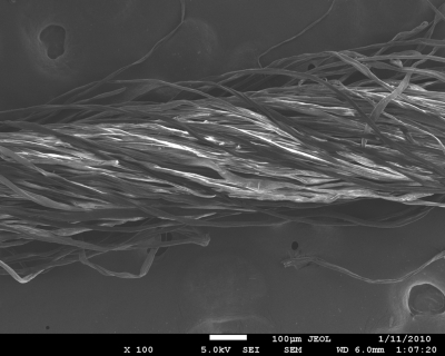
The SEM image in Fig. 1 shows that a polyester thread is formed by many fibers; the gaps between fibers form capillary channels which enable the penetration of a wetting fluid. In μTADs, threads must function as fluid transport channels and detection sites. It is possible to divide a piece of thread into different segments, making these segments fulfill different functions. Such division can be made by applying liquid adhesive or wax onto the thread to occupy the interfiber gaps in a thread, eliminating the capillary channels. In such a way, a piece of thread can be divided into a fluid transport channel and a detection site. Sample fluid in the transport channel cannot enter the detection site without external intervention (i.e., activation by a switch). In many applications, the detection zone requires treatment with indicators that should be localized within the detection zone.17 Segmenting a piece of thread into a transporting channel and detection zone is therefore a necessary fabrication consideration. The sample transporting channel and the detection zone can only be connected when an on∕off switch is activated and the two segments are bridged to enable sample flow across the blockage.
Figure 1.
A SEM image of a polyester thread, showing the individual fibers which comprise the overall structure. Capillary channels are formed by the gaps between fibers, enabling the thread to conduct flow.
Other control mechanisms can further enhance the functions of μTADs. For example, microselectors can be built into μTADs which allow users to direct the samples or reagents they desire to a specific location given multiple options. Moreover, μTADs can be used as controllable micromixers which are useful when a requirement to mix samples and reagents together at a specific time exists. Micro-TADs incorporating all of these new and simple mechanisms are inexpensive and easily fabricated without specialist equipment, and therefore suitable for use in underdeveloped areas, remote regions, or potentially as point-of-care products globally. We expect that by understanding fluid penetration distance and flow rate as well as exploiting a variety of mechanisms for flow control on μTADs, we have provided a means to create more sophisticated and functional μTADs, allowing their further development and expansion of their potential applications.
EXPERIMENTAL
Threads and textile
Polyester thread was kindly provided by the School of Fashion and Textiles, RMIT University, Melbourne, Australia. Untreated polyester thread can be wetted by aqueous solutions, albeit with a slow penetration rate. Plasma oxidation was used to improve fluid penetration along the polyester thread, since such treatment increases the fiber surface polarity by removing surface contamination by low surface energy materials and also oxidizing the fiber surface. Our previous study showed that cotton thread is also a suitable material for fabricating μTADs.17
Measurement of fluid capillary rise on threads
Synthetic food dye solution (Queen Food Coloring, Pillar box red) was used to track the penetration of fluids within thread. The surface tension of the dye solution was measured by the capillary rise method24 using a glass capillary (i.d.=0.9 mm) and cathetometer. The kinematic viscosity of the solution was measured with a U-tube viscometer (BS∕U tube) using Millipore-purified water as the standard solution. Measurement was conducted in a water bath with temperature held at 30±0.1 °C.
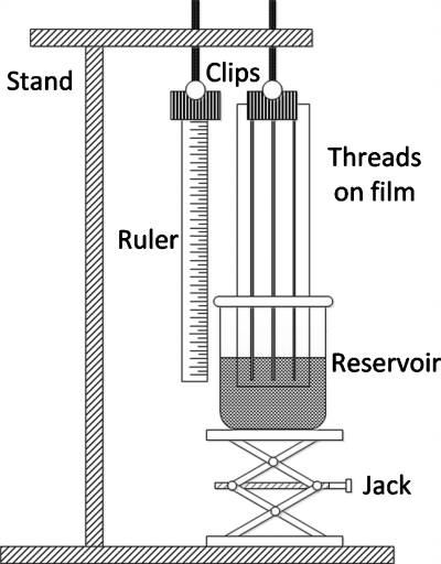
A schematic of the apparatus for measurement of fluid penetration on threads is shown in Fig. 2. A laboratory jack was used to hoist the fluid reservoir containing the dye solution to the appropriate height; a ruler was used to measure the fluid penetration distance on thread. The surface tension and kinematic viscosity of the food dye solution in the reservoir (i.e., beaker) were 65.1 mN∕m and 0.883 cS, respectively (at 30 °C). Fluid penetration was recorded using a camcorder (JVC GZ-MG530) and a snapshot program was used to record time-lapse images. Data acquisition began when threads were dipped into the penetration fluid, with penetration distance recorded for 15 min. Each measurement was repeated six times to give the average penetration distance and standard deviation data. Contact between the polymer film and the threads was restricted by bending the film and fixing only the two ends of the thread to the film, which also served to eliminate the untwisting of the threads.
Figure 2.
A schematic of the apparatus employed for the fluid penetration measurements on thread. Threads were fixed to a polymer supporting film and wet with dye solutions from a fluid reservoir.
Functional elements on μTADs for flow control
In order to selectively inhibit fluid flow along the thread, interfiber channels were blocked using commercially available cyanoacrylate-based fast acting adhesive (Selleys Quick Fix Supa Glue). With the application of glue (0.5 μL, 10 min cure under fume hood), no fluid penetration past the glue-sealed segment is possible, suggesting the complete blockage of the interfiber channels within the thread. Glue can also be employed to fix thread onto polymer film for support. These blocking and adhesive characteristics provide the opportunity to build functional elements into μTADs for more sophisticated fluid flow control.
The first functional element demonstrated for thread-based microfluidics is the binary (on∕off) fluid flow control switch. One simple concept is a “knot style” switch built with only thread itself and glue. The device was made by tying an overhand knot in a polyester thread, and then a small segment of the thread located on the loop is completely blocked to stop fluid flow using glue. Polymer film was also incorporated for some other on∕off flow control designs, polypropylene polymer was selected as the film material due to its hydrophobic nature which eliminates any flow from occurring in the small gap between the thread and the film surface.
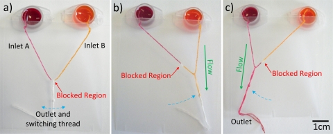
The second functional element is the flow selector. The proof-of-concept design shown consists of two inlets (one thread was separated into two parts by blocking the middle part with glue) and one outlet (one thread was capable of being dragged along the first thread to select the flow from the two inlets).
The third functional element is the micromixer; it is composed of two binary switches which are activated at the same time, enabling a μTAD to mix two solutions from two separate inlets into one outlet by twisting the inlet threads.
Testing solutions
Millipore-purified water was used to prepare all aqueous samples required. Ink solutions (cyan, magenta, and yellow) for visual indication of successful flow control used during experiments were prepared by diluting commercial Canon inkjet inks [CLI Y-M-C-BK, PGBK (http://www.canon.com.au)] with water.
Sample solutions containing analytes of glucose and protein [bovine serum albumin (BSA), ∼66 kDa] were prepared with the artificial urine. Sample solution 1 was a solution of 30 μM BSA and 10 mM glucose in artificial urine.25 The glucose and protein indicator solutions were prepared and applied to the thread using micropipette.25 All reagents were purchased from Sigma-Aldrich.
Sample solutions for micromixer mixing effect tests were HCl (0.01M, solution 2) and NaOH (0.01M, solution 3) solutions which were introduced into two inlets of the micromixer and mixed within a common outlet after folding the μTADs. The commercial pH paper (Advantec, whole range pH test paper) was used to test the pH values of the two inlets and one outlet to show the mixing effect by means of a neutralization reaction.
RESULTS AND DISCUSSION
Fluid penetration along threads
The fluid penetration distance along threads as a function of time was investigated experimentally by the observation of the capillary rise of the testing fluid against gravity. In general modeling of fluid penetration within a porous media, the Washburn equation is used. In the present study, however, since the capillary rising of fluid in threads was investigated against gravity, the capillary driving force must be reconsidered to include gravity.26 The capillary rising model in the literature was adapted in this study to provide an understanding of fluid penetration along threads. Another factor under ambient conditions is fluid evaporation, which will also be discussed qualitatively below.
Wang et al.26 studied the vertical capillary rise and made a derivation using Hagen–Poiseuille’s law [Eq. 1]. In this derivation the authors assumed that the cross section of the interfiber channels in a yarn has an equivalent radius r and the capillary driving force comprises two opposite pressures, the Laplace pressure and the hydraulic pressure due to gravity [Eq. 2],
| (1) |
| (2) |
where h is the fluid penetration distance along the thread, γ, η, and ρ are the fluid surface tension, viscosity, and density, ΔP is the pressure that provides the fluid penetration driving force, and g is the gravitational constant.
Since the helical nature of the interfiber channels (Fig. 1) is not considered, this model will provide a qualitative trend-prediction of the capillary rise in a thread. The helical pathways of the channels have greater length than the actual length of the thread, therefore the fluid rising rate observed experimentally along the thread would be lower than the modeling prediction. Despite this, the qualitative understanding will still provide practical information of fluid penetration along a thread, which is useful for the design of μTADs.
In the original Washburn derivation27 horizontal capillaries were considered and the driving force comprised of only the Laplace pressure. By substituting the Laplace pressure into Eq. 1, the original form of the Washburn equation can be obtained [Eq. 3],
| (3) |
Integrating Eq. 3 with the initial condition of h=0 at t=0 will yield the Washburn equation27
| (4) |
When the capillary height is plotted against the square root of time, a straight line will be obtained.
However, when a vertical capillary is modeled, the gravitational force needs to be considered [Eq. 2]. The fluid penetration kinetics can be written as follows:27
| (5) |
Comparing Eqs. 3, 5, the capillary driving force (bracketed section) in the case of vertical capillary rise decreases as the height of capillary rise increases. Such a height-dependent loss of driving force will cause the plot of capillary rise height against the square root of time to deviate from the straight line of the horizontal capillary penetration model [Eq. 4] at longer penetration time. This study provides the basic experimental data and understanding which will be used as general guidance for the design of functional elements.
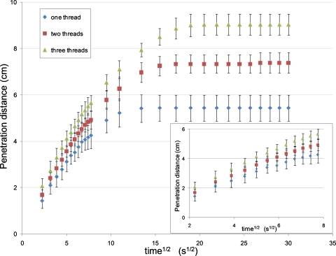
Our experimental data of capillary rise height and the square root of time show a linear relationship when the height is relatively small (Fig. 3), but a gradual deviation from this linear trend as the time of wetting exceeds ∼1 min. Such fluid penetration behavior is in an apparent agreement with the loss of capillary driving force (partially) due to gravity. It can be expected that this deviation from linearity would be delayed if threads were orientated horizontally.
Figure 3.
A graph of penetration distance vs the square root of time for (i) a single thread, (ii) twisted pair, or (iii) twisted triple. The graph highlights a linear relationship between penetration distance and the square root of time over the first minute (∼8√s), concordant with the Washburn equation. After this the curve flattens out and reaches an ultimate penetration distance due to the effects of evaporation and gravity.
Another factor that causes the loss of capillary force is fluid evaporation during the penetration process. This factor is not considered in the modeling above, but is likely to have a dominant effect over longer times, since fluid evaporation will become more and more substantial as the time and the area of fluid on the thread surface exposed to air increase. Fluid evaporation leaves less free fluid in the capillary channels between fibers, reducing the driving force for the fluid flow through fluid starvation. The complete halting of the fluid penetration front as the penetration distance reached 5.4 cm along a single thread is most likely due to the establishment of an equilibrium between fluid evaporation from the wetted thread surface and the capillary fluid uptake from the reservoir. This conclusion is supported by a further observation that the equilibrium height of capillary rise in a single thread is higher if fluid evaporation is reduced by covering the thread with film. The understanding of fluid penetration behavior along a single thread enables a basic degree of prediction which can be used in the design of μTADs.
The effect of twisting multiple threads together was investigated by comparing the fluid penetration on a single thread, double-twisted threads, and triple-twisted threads (the twisting frequency is around 200 twists∕m). The major geometric feature of the twisted threads is the generation of interthread gaps; these gaps are much larger than interfiber gaps in a thread. The shape of an interthread gap may be crudely viewed as analogous to a “V-groove.” Rye et al.28 modeled fluid flow in a V-groove driven by capillary force and found that fluid penetration rate in a V-groove driven by capillary force can be described by a pseudo-Washburn relationship (i.e., penetration distance ∝ square root of time). These authors also showed that fluid penetration rate in V-grooves is proportional to the cross sectional width of the groove, and is sensitive to the groove apex angle (the angle between the two walls of the V-groove). Our experimental data show that fluid penetration rates along double-twisted threads are greater than that of a single thread. The fluid shows even higher penetration rate along triple-twisted threads than double-twisted threads, since the former have more interthread gaps. These observations agree with the general trend of the V-groove model and this model can be used to provide a qualitative description of the twisted threads. Furthermore, gravitational and fluid evaporation effects can also be seen from the penetration results for twisted threads. Since the interthread V-grooves increase fluid uptake from the reservoir, the equilibrium of the fluid uptake and fluid evaporation occurs at a higher capillary rise (Fig. 3).
The experimental study of fluid penetration along threads mentioned above suggests that only moderate lengths are appropriate for building functional elements for control of fluid transport. Also, twisted threads can be used for the design of a fluid splitter or a mixer where a sufficient fluid supply needs to be provided to suffice two split flows and vice versa. Moreover, variation of fluid flow rate on μTADs can be easily achieved by twisting threads together, useful knowledge for the design of devices.
Building functional elements on μTADs for controlled fluid transport
For traditional microfluidic devices, some useful features such as flow control microvalves and fluid micromixers have been successfully built into devices for sophisticated fluid control. However, similar techniques are still unavailable for μTADs. It is expected that achieving better control over flow connection∕disconnection, fluid selection and mixing on μTADs will accelerate the development of μTADs and widen the applicability of thread-based microfluidics.
Binary type (on∕off) switches
The binary type switch works on the principle of using a blocking point to disable fluid transport between two segments of a piece of thread (off), but enable fluid transport when activated by by-passing the blocking point (on). As mentioned earlier, the isolation of the detection zone from the sample introduction channel is necessary for the device fabrication and function. Another desired feature in some analyses is to stop the back flow of the indicator from the detection zone to the channel after the sample delivery.17 With the switch, this can be done by “turning off” the switch after the sample introduction. The advantage of using glue to form blocking points in thread over using reactive chemical hydrophobization methods is that the blocking points can be formed over a short stretch of thread, and even withstand surfactant solutions with a depressed surface tension as the capillary channels have been effectively eliminated over the range of the blockage.
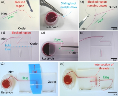
The simplest of the designs presented here uses a knot in a single piece of thread to create a basic on∕off flow control mechanism, as shown in Fig. 4a. Diluted inkjet magenta ink was used to examine the on∕off flow along the knotted switch. An overhand knot with a draw loop29 was tied loosely in a thread such that it could slide along the length of the thread. A section of the draw loop was then blocked against fluid flow using glue, and the knot slid and placed over this blocked region so that the switch was in the “off” position and the ink was unable to penetrate through this region [Fig. 4a(1)]. After sliding the knot away from the blocked region, the ink can flow across the knot and through the length of the thread [Fig. 4a(2)], while the blocked region remains unwet by the fluid.
Figure 4.
(a) The simplest of the “on∕off” flow control switches is comprised of a thread which incorporates a knot and a loop with an adhesive-blocked segment, sliding the knot over the blocked segment in the loop enables flow to occur along the length of the thread. (a1) The knot device with the inlet fully wet by ink solution, the blockage caused by the glue is indicated by the red dashed line. (a2) The partially wetted device with the inlet in an ink reservoir after being actuated by sliding the knot past the blocked region. (a3) The device after being removed from the reservoir after conducting flow from inlet to outlet. (b) The folding style switch makes use of a polymer film supporting material to function. (b1) The fold type switch in the open position with the inlet wet by ink. The fold line and blocked region are labeled. (b2) The folded device allowing flow from an ink reservoir at its inlet. (b3) The fully wetted device after being used to transport fluid (device having been reopened). (c) Folding style switches can be modified to be pull-tab actuated. (c1) The pull-tab switch with inlet connected to an ink reservoir. (c2) The pull-tab switch with tab removed, allowing flow across the device.
When polymer film is used as a supporting material for μTADs design, on∕off flow control can be easily achieved in a variety of ways. In this study, we demonstrated different mechanisms of on∕off control in μTADs. These mechanisms included folding the polymer film or removing a temporary obstruction such as a pull-tab.
A simple folding style switch is shown in Fig. 4b. The device was constructed by folding the polymer film into two smaller rectangles of equal area. On one side of the fold, a thread was stitched into the film running parallel with the crease line of the fold, but with a “z” shaped kink in the center. The diagonal section of the z shape was then blocked using adhesive to prevent the flow. On the opposing side of the film, a small bridge was sewn which was perpendicular to the fold line and directly opposite the center of the z shape. The device is activated by folding the film and bringing threads on opposing sides into contact with each other. The small thread section on the left acts as a bridge allowing flow to jump between different sections of the partially blocked thread on the right. Additionally, other porous materials such as textile and paper can be used to act as bridges to allow on∕off flow control on thread.
In a pull-tab activated on∕off flow control mechanism, a small removable section of polymer film [blue film in Fig. 4c] was inserted into the device to form a barrier to flow between opposing threads sewn to the top and bottom films of the device. When the tab is removed by the user pulling upon it, threads on opposing sides of the device are brought into contact with each other and the switch is activated. An advantage of this actuation method is its ease of use, as it eliminates the need for users to hold the device folded shut, and minimizes user contact with the internals of the device. Should an application require the incorporation of hazardous reagents, designers could enclose them entirely within plastic films, reducing the risk of user contact.
An important future application of on-off switches will be to fabricate thread-based microreactors, which allow different reagents to be introduced into reaction zones simultaneously or separately in multistep reactions, or provide controllable reaction time for detection chemistries which require multiple steps, e.g., in blood and urine testing, an analyte may need to be converted into a more detectable form using an enzyme before final detection.
Microselectors for flow control
The two-way microselector device shown in Fig. 5 allows a user to choose between samples or reagents (magenta and yellow inks as example solutions here) at two inlets and direct flow down a particular outlet channel at the time the user desires. Alternatively the device can function in reverse, with a single sample or reagent directed to a desired outlet selected from two or more options. Such a device could be useful in complex systems which possess multiple reaction or detection sites, enabling users to selectively perform different types of analyses with the same device.
Figure 5.
A microselector, with two inlets and a single outlet, allows a user to select between which one of two samples they wish to transport. Ink solutions are used for visualization of the concept. (a) The unused selector switch set in the off position. The blocked region is indicated and the inlets are connected to ink solution reservoirs. (b) The selector switch after sliding to the right, allowing flow of the yellow ink to the outlet. (c) The selector switch after sliding left, allowing flow of magenta ink.
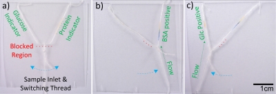
To illustrate the thread-based microselector applicability to bioassays, a sample solution containing both glucose and protein (sample solution 1) was used to show one possibility for directing sample flow into different outlet channels (Fig. 6). The glucose and protein indicators (0.1 μL) were deposited onto the upper left and right threads (i.e., the left and right outlet channels), respectively. The indicators were then allowed to dry under ambient conditions for 15 min. The sample solution was introduced from the lower thread (i.e., the inlet channel). When the sample solution was selected to flow into the right outlet channel by moving the loop to the right, the color change of protein indicator from yellow to blue-green showed that the sample solution had arrived at the desired channel. The loop was then moved to the left to direct the sample flow into the left outlet channel, which was shown by the development of a yellowish brown color caused by the glucose indicator present. The results showed that the transport of multiple fluid flows can be controlled with the sequential delivery of fluids within μTADs, thus extending the capabilities and performance of μTADs while still at low manufacturing cost.
Figure 6.
The microselector allows a user to select between which analyte they wish to analyze. (a) The unused selector switch set in the off position. The blocked region is indicated by a red dashed line, and indicator locations are noted. (b) The selector switch allowing flow to the right, resulting in a color change indicating the presence of protein. (c) The selector switch allowing flow to the left, the presence of glucose is indicated.
Micromixers
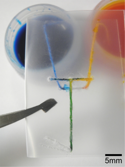
Mixing is an important feature in microfluidic devices, required for various chemical functions. The ability to mix reagents and samples gives a designer of μTADs access to a suite of detection chemistries not available when using only “single step” functionality. This could include sensing systems where an analyte can only be detected after it has been chemically converted to a different form or instances where a colorimetric indicator compound requires a second reaction to produce its visual effect. The flexibility of thread makes it a suitable material for mixing fluids, simply by twisting threads together (i.e., coupling multiple inlets to a single outlet). High twist level maximizes the contact areas between threads (two or more) and therefore increases the diffusion interface and enables fluid mixing. The device shown in Fig. 7 achieved the desired mixing of two colored inks when the device was folded to bring the two wet thread sections in contact with a mixing zone. Thread-based micromixers can also be fabricated with “pull-tab” activation mechanisms.
Figure 7.
A micromixer device used to mix two colored inks together. The green color produced illustrates the efficacy of the device.
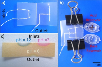
The efficacy of the thread-based micromixer was shown by testing an acid-base neutralization reaction (Fig. 8). HCl and NaOH solutions (solutions 2 and 3) with equivalent molarity (0.01M) were used as sample solutions in this test. The ends of two inlets of the μTAD were immersed into two reservoirs filled with solutions 2 and 3, respectively. After the solutions had fully wet the two inlets, the device was folded (by hand, tweezers, or clippers) to direct two solutions into the twisted threads simultaneously for mixing [Fig. 8b]. Universal pH test paper was used to test the pH values for three points: (i) middle of inlet transporting solution 2, (ii) middle of inlet transporting solution 3, and (iii) 1 cm from the intersection of the twisted threads (outlet) [Fig. 8c]. The theoretical pH values of solutions 2 and 3 are 2 and 12, respectively, which are concordant with the testing values of the first and second test points (at the inlets) from the 12 repeated measurements. For the third test point (i.e., the outlet or reaction product point), readings were recorded at 1 and 3 min after the device being folded. All measurements were repeated 12 times and the results showed that for this test point, the pH value varied between 6 and 8. Compared with the theoretically expected pH value of 7 for the reaction product, the measured values indicated that the unneutralized reagent concentration is at most 10−6M (i.e., ≥99.99% conversion), showing the intended neutralization and hence mixing capability of the thread-based micromixer.
Figure 8.
A micromixer used to neutralize acid and base solutions to demonstrate the possibility of high quality mixing. (a) The unused mixer with inlets on the left and outlet on the lower right. (b) The device in use with one acid inlet (0.01M HCl), one base inlet (0.01M NaOH), and reservoirs. The device is held shut by bulldog clips. (c) pH paper showing measurements from the inlets (pH 2 and 12) and outlet (pH 6), suggesting that 99.99% of the acid was neutralized by the base.
The concept of building thread-based functional elements (e.g., switches, microselectors, and micromixers) into low-cost μTADs is valuable for more advanced fluid flow control and provides possibilities for performing multistep reactions on μTADs without compromising the low fabrication cost and ease of use.
CONCLUSIONS
This study shows that the ability to control flow on thread allows for more sophisticated functions to be built into μTADs. The measurement of fluid penetration distances and flow rates on thread is an important consideration for the design of μTADs and understanding fluid transport in these devices. The capacity to mix and select between reagents enables the user to create devices with higher functionality, and facilitates the incorporation of more complex chemistries. The results of this work show that such devices can be made simply and cheaply by relatively unskilled persons using inexpensive materials.
Various mechanisms of flow control (i.e., functional elements) have been demonstrated in this study, with the most basic being the binary on∕off style switch which is useful for controlling the timing of fluid introduction to reactors or other channels. More sophisticated designs included microselectors which give the user the ability to direct flow to one specific outlet given multiple choices. It was also shown that microselectors could function in reverse, with the user selecting one of several samples to be directed into a single outlet. Micromixers which could effectively mix multiple fluids together at a desired time were also developed, allowing the inclusion of multiple-step chemistries into thread-based microfluidics. For these functional elements of thread microfluidic systems, actuation can also be achieved by incorporating external elements (e.g., magnetic or electronic elements) to trigger folding or tab pulling and prolonged closure of the devices.
Concepts presented in this study have provided more flexibility for the design of μTADs by giving designers new mechanisms for the control of fluid flows without compromising the distinctive properties of μTADs, such as low cost and ease of use. It is hoped that this addition to knowledge in the field can be utilized to create more functional devices for the detection of disease, environmental contamination, or other novel applications.
ACKNOWLEDGMENTS
The research scholarships of Monash University and the Department of Chemical Engineering are gratefully acknowledged. The authors thank Dr. L. Wang of the School of Fashion and Textiles, RMIT University, for kindly providing us with thread and textile samples, Ms. Y. H. Ngo for assistance in obtaining SEM images, and Mr. K. Wu for assistance in generating fluid penetration data.
References
- Mabey D., Peeling R. W., Ustianowski A., and Perkins M. D., Nat. Rev. Microbiol. 2, 231 (2004). 10.1038/nrmicro841 [DOI] [PubMed] [Google Scholar]
- von Lode P., Clin. Biochem. 38, 591 (2005). 10.1016/j.clinbiochem.2005.03.008 [DOI] [PubMed] [Google Scholar]
- Lee W. G., Kim Y.-G., Chung B. G., Demirci U., and Khademhosseini A., Adv. Drug Delivery Rev. 62, 449 (2010). 10.1016/j.addr.2009.11.016 [DOI] [PMC free article] [PubMed] [Google Scholar]
- Yager P., Domingo G. J., and Gerdes J., Annu. Rev. Biomed. Eng. 10, 107 (2008). 10.1146/annurev.bioeng.10.061807.160524 [DOI] [PubMed] [Google Scholar]
- Yager P., Edwards T., Fu E., Helton K., Nelson K., Tam M. R., and Weigl B. H., Nature (London) 442, 412 (2006). 10.1038/nature05064 [DOI] [PubMed] [Google Scholar]
- Fenton E. M., Mascarenas M. R., López G. P., and Sibbett S. S., ACS Applied Materials & Interfaces 1, 124 (2009). 10.1021/am800043z [DOI] [PubMed] [Google Scholar]
- Li X., Tian J., Garnier G., and Shen W., Colloids Surf., B 76, 564 (2010). 10.1016/j.colsurfb.2009.12.023 [DOI] [PubMed] [Google Scholar]
- Martinez A. W., Phillips S. T., Whitesides G. M., and Carrilho E., Anal. Chem. 82, 3 (2010). 10.1021/ac9013989 [DOI] [PubMed] [Google Scholar]
- Li X., Tian J., Nguyen T., and Shen W., Anal. Chem. 80, 9131 (2008). 10.1021/ac801729t [DOI] [PubMed] [Google Scholar]
- Qi A., Yeo L., Friend J., and Ho J., Lab Chip 10, 470 (2010). 10.1039/b915833b [DOI] [PubMed] [Google Scholar]
- Lu Y., Shi W., Jiang L., Qin J., and Lin B., Electrophoresis 30, 1497 (2009). 10.1002/elps.200800563 [DOI] [PubMed] [Google Scholar]
- Abe K., Suzuki K., and Citterio D., Anal. Chem. 80, 6928 (2008). 10.1021/ac800604v [DOI] [PubMed] [Google Scholar]
- Noh H. and Phillips S. T., Anal. Chem. 82, 4181 (2010). 10.1021/ac100431y [DOI] [PubMed] [Google Scholar]
- Pelton R., TrAC, Trends Anal. Chem. 28, 925 (2009). 10.1016/j.trac.2009.05.005 [DOI] [PMC free article] [PubMed] [Google Scholar]
- Khan M. S., Thouas G., Shen W., Whyte G., and Garnier G., Anal. Chem. 82, 4158 (2010). 10.1021/ac100341n [DOI] [PubMed] [Google Scholar]
- Martinez A. W., Phillips S. T., Butte M. J., and Whitesides G. M., Angew. Chem., Int. Ed. 46, 1318 (2007). 10.1002/anie.200603817 [DOI] [PMC free article] [PubMed] [Google Scholar]
- Li X., Tian J., and Shen W., ACS Applied Materials & Interfaces 2, 1 (2010). 10.1021/am9006148 [DOI] [PubMed] [Google Scholar]
- Safavieh R., Mirzaei M., Qasaimeh M. A., and Juncker D., Proceedings of MicroTAS 2009, The 13th International Conference on Miniaturized Systems for Chemistry and Life Sciences, ICC Jeju, Jeju, South Korea, 1–5 November 2009.
- Reches M., Mirica K. A., Dasgupta R., Dickey M. D., Butte M. J., and Whitesides G. M., ACS Applied Materials & Interfaces 2, 1722 (2010). 10.1021/am1002266 [DOI] [PubMed] [Google Scholar]
- Osborn J. L., Lutz B., Fu E., Kauffman P., Stevens D. Y., and Yager P., Lab Chip 10, 2659 (2010). 10.1039/c004821f [DOI] [PMC free article] [PubMed] [Google Scholar]
- Fu E., Ramsey S., Kauffman P., Lutz B., and Yager P., Microfluid. Nanofluid. 10, 29 (2011). 10.1007/s10404-010-0643-y [DOI] [PMC free article] [PubMed] [Google Scholar]
- Fu E., Lutz B., Kauffman P., and Yager P., Lab Chip 10, 918 (2010). 10.1039/b919614e [DOI] [PMC free article] [PubMed] [Google Scholar]
- Fu E., Kauffman P., Lutz B., and Yager P., Sens. Actuators B 149, 325 (2010). 10.1016/j.snb.2010.06.024 [DOI] [PMC free article] [PubMed] [Google Scholar]
- Shaw D. J., Introduction to Colloid and Surface Chemistry (Butterworth-Heinemann, Ann Arbor, 1992). [Google Scholar]
- Martinez A. W., Phillips S. T., and Whitesides G. M., Proc. Natl. Acad. Sci. U.S.A. 105, 19606 (2008). 10.1073/pnas.0810903105 [DOI] [PMC free article] [PubMed] [Google Scholar]
- Wang N., Zha A., and Wang J., Fibers Polym. 9, 97 (2008). 10.1007/s12221-008-0016-2 [DOI] [Google Scholar]
- Washburn E. W., Phys. Rev. 17, 273 (1921). 10.1103/PhysRev.17.273 [DOI] [Google Scholar]
- Rye R. R., Yost F. G., and Mann J. A., Langmuir 12, 4625 (1996). 10.1021/la9605201 [DOI] [Google Scholar]
- Budworth G., Essential Knots & Basic Ropework (Lorenz, New York, 2000). [Google Scholar]


