Abstract
Previous works have shown that placement of a high-dielectric pad can improve image intensity in a region adjacent to the pad, or that placement of dielectric pads around a large surface of the head can improve image homogeneity on an entire plane through the head in high-field MRI. Here, experimental results show that use of high-dielectric pads around the human head can reduce the required input radiofrequency power by 50% while enhancing image signal-to-noise ratio by 20–40% throughout the cerebrum at 3 T. Thus, dielectric pads may be used to provide a relatively simple and low-cost method for improving quality and safety of MRI in a variety of applications at 3 T.
Keywords: MRI, B1 field, RF field, SAR, SNR, permittivity
Recent experiments have shown that the high dielectric constant of human tissues plays an important role in radiofrequency (RF) field behavior in the human body, with significant implications for high-field MRI (1–5). The electrical properties, geometry, and relative position of the sample in the coil become important factors in determining the B1 field distribution inside the sample (3,6,7). Consequently, adjustment of B1 field distribution inside the sample and the coupling between the sample and coil can be facilitated with high permittivity materials (4,7–11). In this context, dielectric focusing and shimming of RF field were proposed at 7 T by placement of high dielectric pads to either (1) locally enhance fields to increase image intensity in a relatively small region of interest (ROI) near the pad (1,11) or (2) shim the fields to compensate for the center-bright artifact (11). In this study, we present experimental results of human head imaging at 3 T, which demonstrated that the RF power for a 180° excitation pulse can be reduced by ∼50% while enhancing signal-to-noise ratio (SNR) of image of cerebrum by 20–40% by placing high dielectric (water) pad around the human head. Our in vivo data demonstrated that the efficiency of a given RF coil can be enhanced by incorporating dielectric materials into the RF coil at 3 T.
Theory
For conductive dielectric materials such as human brain tissues, the RF field inside the sample is perturbed by conductive current (Jc) and displacement current (Jd), according to Ampere's law with Maxwell's correction,
| [1] |
where B is magnetic flux density, E is electric field, ϖ is angular frequency, εr is relative electric permittivity (dielectric constant), ε0 is electric permittivity in vacuum, σ is electrical conductivity, μ is magnetic permeability, and is the complex unit that introduces a 90° phase difference between conductive current and displacement current (12). For plane waves travelling in a homogeneous medium, the conductive current leads to decay of the RF field in the direction of propagation, whereas the displacement current with a 90° phase shift acts as a secondary field source facilitating RF wave propagation. In this case, the contributions of the two opposing sources to B1 can be considered using ratio Jc and Jd given by
| [2] |
In principle, materials with low σ and high εr can enhance the local B1 field strength for an RF field frequency range high enough to induce the displacement current much stronger than conducting current. Thus, placement of dielectric pads near the ROI in MRI should result in enhanced local B1 field strength with concomitant improvement of signal to noise ratio (SNR) and reduction of overall specific absorption rate (SAR).
Materials and Methods
Human brain images were acquired on a 3-T whole body system (Bruker, Biospin, Ettlingen, Germany) using a quadrature 12-element high-pass birdcage coil with 26 cm inner diameter and 29 cm length. Axial brain images were acquired with identical imaging parameters with and without a dielectric pad placed around the head and after the coil was tuned and matched, and RF power was calibrated for each condition. The subject remained in the magnet during the process of placing and/or removing the dielectric pad, retuning the coil, and adjusting the RF power for 90°/180° flip angle (FA). Power for the FA was adjusted manually with and without the pad while maximizing the total signal on five axial slices covering a 2.5-cm slab through the center of the brain. The pad, containing ∼6 L of distilled water, was conformed around the superior portion of the head extending to just above the level of the eyes in front, just above the ears on the sides, and just below the end of the skull in the back of the head. Fast spin-echo (RARE) images with slice thickness = 5 mm, matrix = 128 × 128, FA = 180°, and field of view = 30 cm were acquired on five axial, sagittal, and coronal planes spaced 5 mm apart through the cerebrum. The experiment was repeated four times with two human subjects. All the subjects provided written informed consent before participation, in accord with the requirements of the Institutional Review Board of the Pennsylvania State University College of Medicine.
SNR was measured using the magnitude images acquired under the above two conditions. The average signal intensity was calculated in an elliptical ROI covering most of the cerebrum in each of the 15 images acquired with and without the dielectric pad. Examples of the elliptical region in each orientation are shown in Fig. 1. The noise was measured by calculating the standard deviation in an ROI covering 29 cm2 in a region of no visible signal or artifact across the top of each image.
FIG. 1.
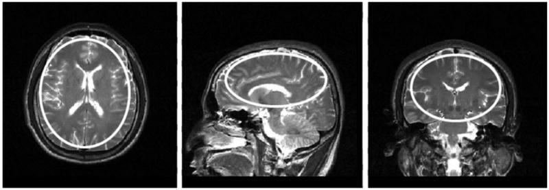
Examples of elliptical ROI used to evaluate T2-weighted image intensity for SNR measurement and uniformity assessment on mid-axial (left), sagittal (center), and coronal (right) planes.
To further understand the effect of the dielectric pad, a numerical model with finite difference time domain method was used to calculate the RF field distribution in the sample and coil model shown in Fig. 2a at 128 MHz (3 T). All the finite difference time domain calculations were performed with commercially-available software (XFDTD; Remcom, State College, PA), and postprocessing of the simulation results was performed with home-built programs in MATLAB (The Mathworks, Natick, MA). A three-dimensional mesh with isometric 2 mm resolution was created within a region of 57 × 50 × 42 cm3. The calculation was performed with −35 dB convergence to ensure that the steady state was reached. A Liao boundary condition was used for the outer boundary truncation of the grid. The coil was modeled after that used in experiment: a copper 12-rung high-pass birdcage coil (32.8 cm i.d. and 25.4 cm length, shield diameter of 40.0 cm). The coil model was driven by 12 current sources at the locations of the capacitors in the actual coil on each of the two end-rings with each having a 30 degree phase shift. The human head model used for the finite difference time domain calculation included 16 types of tissues, and the corresponding electric properties of dielectric pad at 128 MHz were modeled with a 3-cm thick uniform layer of water. The human head model used for the finite-difference-time-domain calculation included 16 types of tissues, and the water pad was modeled with a 3-cm thick uniform layer of dielectric material over the head excluding the face as shown in Fig. 2b with electric properties of water at 128 MHz (σ = 0.0047 S/m2, εr = 78).
FIG. 2.
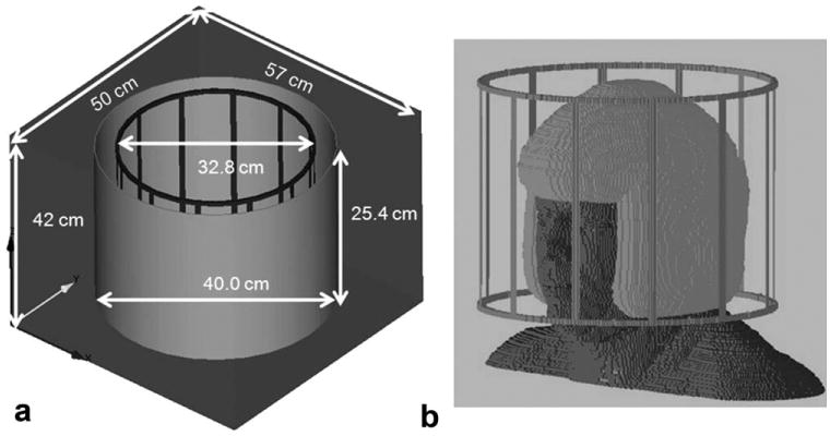
Computer models of the bird-cage coil (a) and human head with the dielectric pad (b).
Results
Figure 3 shows an axial image through the center of the brain after addition of the dielectric pad and retuning of the coil, but before reoptimization of the RF power levels (using power values optimized without the pad) on the left, and after reoptimization of the RF power levels with the pad on the right. After addition of the pad, the RF power levels that previously generated 90°/180° excitation/refocusing pulses in the brain created much larger FAs due to enhancement of the B1 field. A 3-dB reduction of power for both the excitation and refocusing pulses was required to maximize the signal.
FIG. 3.
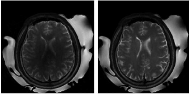
Overtipping resulting in dark region in brain after addition of dielectric pad (left) and improvement after reduction of RF power (right).
Figure 4 shows images acquired with and without the dielectric pad on axial, sagittal, and coronal planes. The SNR in the brain measured in the elliptical regions indicated in Fig. 1 is listed below each corresponding image. For all 15 planes acquired, the SNR increased by 20–40% (in average, 27%) with addition of the dielectric pad; whereas, the overall uniformity of image intensities appear to be similar in both cases. The SNR of repeated experiments are within the same range.
FIG. 4.
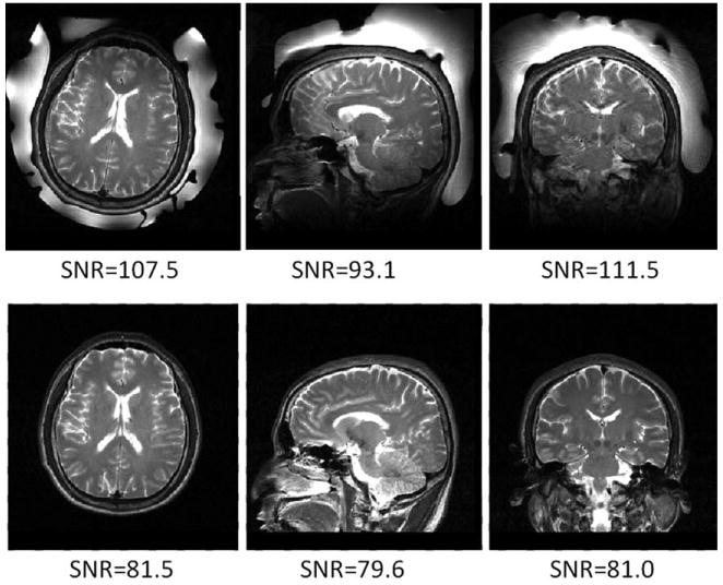
Axial, sagittal, and coronal images through brain with (top) and without (bottom) dielectric pad. Measured SNR values in regions indicated on Fig. 1 are given under each image.
Figure 5 shows the calculated distributions with and without the dielectric pad in three orthogonal planes arranged as in the experimental results. All the fields correspond to 1 W of power delivered to the coil. The calculated distributions under the two conditions presented similar characteristics as the in vivo images in Fig. 4. The RF field appears to be greater inside the brain regions surrounded by the dielectric pad but lower in the regions in the face and neck outside of the padded region. outside the upper portion of the head and pad is lower, when the dielectric pad is present, and the same input power is maintained. This can be seen in the line plots at the bottom of the figure, which present along the dotted lines in the maps above in Fig. 5. The red and blue lines indicate for cases with and without the dielectric pad, respectively. The RF field around the coil elements and in between the coil element and shield (seen most clearly in the middle line plot) was reduced to >70%, indicating less current is required in the coil to maintain the same RF power level when the pad is present. In ROIs, similar to those used in the in vivo results, the average in the simulation is seen to increase by 12–20% with dielectric pad, whereas the source current in the coil is reduced. These computer modeling results demonstrated that the dielectric pad improves the efficiency of generation of B1 field by a given RF coil, resulting in an increase in image SNR and decrease of RF power required for a given FA.
FIG. 5.
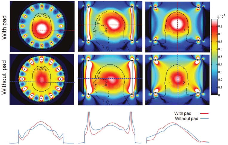
Calculated maps at 128 MHz in three orthogonal planes with (top row) and without the dielectric pad (middle). The distributions along the dotted lines in the corresponding maps are plotted on the bottom. All the maps are scaled to 1 W input power.
Discussion
Addition of a high-dielectric pad surrounding the head resulted in a reduction of required RF power by ∼50% and an increase in image SNR by ∼27% with a transmit/receive volume coil at 3 T. No obvious local bias field induced by dielectric pad in the entire cerebrum was observed in the images in Fig. 4. In addition, image uniformity within the cerebrum was appeared to be somewhat improved. The standard deviation of the signal intensity distribution in the elliptical regions on all 15 images acquired from approximately the same brain volume has decreased by an average of 12% with addition of the dielectric pad. However, caution should be exercised here in interpreting this as an increase in overall image uniformity, solely because the image contrast changes among the multiple tissues included in the human head, which could also contribute to overall image intensity distribution. The uniformity in this brain area is normally interference by the so-called bright center spot due to the RF wave effect.
Comparing images in Fig. 4 acquired with and without the pad showed that the image intensity in the cerebrum relative to the neck and face is much greater with the pad than without it. It is likely that this is due to the enhancement of the B1 field for a given input power in the regions that were surrounded by the pad. B1 field distribution of the coil is altered by the strong displacement currents in the region of the pad, resulting in stronger B1 fields in the vicinity of the pad. Our data suggested that the regional enhancement of the B1 fields in the ROI as demonstrated previously at 4 T and 7 T can be extended to the entire cerebrum with proper coverage by the high dielectric pad, although the B1 field outside the sample is decreased. As a direct result, average SAR levels for the brain imaging will be lowered with the pad, and because SNR is proportional to the ratio of the B1 field strength to the square root of the corresponding RF power, SNR is increased with addition of the pad. The numerical modeling results summarized in Fig. 5 are consistent with our experimental data and clearly demonstrate the enhancement of the B1 field in the cerebrum by the high-dielectric pad. The B1 field is increased in the entire cerebrum region, while outside the brain appears to be reduced by the placement of the dielectric pad, when the maps are normalized to unit input power. Under this condition, is increased in the cerebrum with reduced input current in the coil. This is apparent in the middle line plot, where the two ends of the line pass through coil current elements. As the magnetic field in the upper portion of the head is relatively high compared with elsewhere, a greater percentage of the input power is also dissipated in that region. To maintain the same total input power as is the case in Fig. 5, the coil requires less current and produces lower in regions outside the pad compared with the case when the pad is not present. Thus, overall, the presence of the pad improves efficiency of delivery of both B1 field and RF energy to the portion of the head surrounded by the dielectric pad.
Additional mechanisms by which adding high dielectric materials into RF coil improve the image quality might include impedance matching at the boundaries of the sample (7) or shielding of the sample from the conservative electric fields generated by the charge distribution on the coil (14,15). Given the strong disparity in permittivity of skin, fat, bone, brain, and cerebrospinal fluid, however, presents many layers that are not well impedance matched with or without the presence of the dielectric pad. In particular, cortical bone is electrically much more similar to air at RFs than to brain, so addition of the dielectric padding might be seen to add an additional poorly-matched boundary rather than improving matching at an outer boundary. In samples with diameters of a few millimeters, it has been possible to shield the sample from the conservative electrical fields of the coil with conductive (14) or dielectric materials (14), resulting in lower SAR and increased SNR. This conservative component of the electric fields, however, is expected to become small in comparison with the magnetically-induced component, as sample size increases (16). Also, the reduction of a conservative component should in principle not affect the B1 distribution, and thus would not explain the increase in B1 strength in the sample.
Although more work is required to fully understand and explore the possibilities and limitations of dielectric padding for reducing SAR and improving regional SNR in MRI, the in vivo data presented here at 3 T suggested that dielectric padding around the head or other parts of the anatomy could be used to enhance performance of an RF coil in a variety of cases. A dielectric pad with adjustable volume could be used to enhance RF coil performance, while simultaneously providing comfort and reduction of patient motion. This could be particularly beneficial for pediatric patients, as most RF coils are designed to accommodate larger adult anatomies. In some cases, there may also be advantages to incorporating dielectric material directly into RF coils. Further study is in progress to determine the locations, dimensions, geometries, and permittivity distributions of the material for optimal B1 enhancement.
Water was used in this experiment as a dielectric medium to demonstrate the desired effect. Water has relatively high dielectric constant and low conductivity, is readily available, inexpensive, and nontoxic. However, from a technical point of view, water is unlikely to be the most suitable dielectric material for many applications because it produces strong signal that saturates the receiver and decreases the dynamic range of the digitizer and its movements and geometry are difficult to control. Heavy water (D20) has been used previously (14), but its high expense is prohibitive. Most recently, a new high dielectric constant material based on metal titanates slurry suspension has been shown more effective in tailoring RF field than water (16). Some work with ceramic materials has also been explored for creating dielectric resonators (17), but challenges in achieving specific shapes in this material are significant.
In conclusion, we have demonstrated that strategic placement of dielectric pads around the head within a given RF coil at 3 T can result in reduced RF transmission power and improved image SNR throughout the cerebrum. With further exploration and development, use of dielectric pads may provide a relatively simple and low-cost method for improving quality and safety of MRI in a variety of applications.
Acknowledgments
Grant sponsor: NIH; Grant numbers: R01 EB000454 and R01 AG02771; Grant sponsor: Pennsylvania Department of Health.
References
- 1.Alsop DC, Connick TJ, Mizsei G. A spiral volume coil for improved RF field homogeneity at high static magnetic field strength. Magn Reson Med. 1998;40:49–54. doi: 10.1002/mrm.1910400107. [DOI] [PubMed] [Google Scholar]
- 2.Abduljalil AM, Kangarlu A, Zhang X, Burgess RE, Robitaille PM. Acquisition of human multislice MR images at 8 Tesla. J Comput Assist Tomogr. 1999;23:335–340. doi: 10.1097/00004728-199905000-00001. [DOI] [PubMed] [Google Scholar]
- 3.Yang QX, Wang J, Zhang X, Collins CM, Smith MB, Liu H, Zhu XH, Vaughan JT, Ugurbil K, Chen W. Analysis of wave behavior in lossy dielectric samples at high field. Magn Reson Med. 2002;47:982–989. doi: 10.1002/mrm.10137. [DOI] [PubMed] [Google Scholar]
- 4.Yang QX, Wang J, Collins CM, Smith MB, Zhang X, Ugurbil K, Chen W. Phantom design method for high-field MRI human systems. Magn Reson Med. 2004;52:1016–1020. doi: 10.1002/mrm.20245. [DOI] [PubMed] [Google Scholar]
- 5.Van de Moortele PF, Akgun C, Adriany G, Moeller S, Ritter J, Collins CM, Smith MB, Vaughan JT, Ugurbil K. B(1) destructive interferences and spatial phase patterns at 7 T with a head transceiver array coil. Magn Reson Med. 2005;54:1503–1518. doi: 10.1002/mrm.20708. [DOI] [PubMed] [Google Scholar]
- 6.Vaughan JT, Garwood M, Collins CM, Liu W, DelaBarre L, Adriany G, Andersen P, Merkle H, Goebel R, Smith MB, Ugurbil K. 7T vs. 4T: RF power, homogeneity, and signal-to-noise comparison in head images. Magn Reson Med. 2001;46:24–30. doi: 10.1002/mrm.1156. [DOI] [PubMed] [Google Scholar]
- 7.Caserta J, Beck BL, Fitzsimmons JR. Reduction of wave phenomena in high-field MRI experiments using absorbing layers. J Magn Reson. 2004;169:187–195. doi: 10.1016/j.jmr.2004.03.027. [DOI] [PubMed] [Google Scholar]
- 8.Wen H, Jaffer FA, Denison TJ, Duewell S, Chesnick AS, Balaban RS. The evaluation of dielectric resonators containing H2O or D2O as RF coils for high-field MR imaging and spectroscopy. J Magn Reson B. 1996;110:117–123. doi: 10.1006/jmrb.1996.0019. [DOI] [PMC free article] [PubMed] [Google Scholar]
- 9.Bomsdorf H, Helzel T, Kunz D, Roschmann P, Tschendel O, Wieland J. Spectroscopy and imaging with a 4 tesla whole-body MR system. NMR Biomed. 1988;1:151–158. doi: 10.1002/nbm.1940010308. [DOI] [PubMed] [Google Scholar]
- 10.Foo TK, Hayes CE, Kang YW. Reduction of RF penetration effects in high field imaging. Magn Reson Med. 1992;23:287–301. doi: 10.1002/mrm.1910230209. [DOI] [PubMed] [Google Scholar]
- 11.Yang QX, Mao W, Wang J, Smith MB, Lei H, Zhang X, Ugurbil K, Chen W. Manipulation of image intensity distribution at 7.0 T: passive RF shimming and focusing with dielectric materials. J Magn Reson Imaging. 2006;24:197–202. doi: 10.1002/jmri.20603. [DOI] [PubMed] [Google Scholar]
- 12.Johnk CTA. Engineering electromagnetic fields and waves. New York: Wiley; 1988. [Google Scholar]
- 13.Gabriel C. AL/OE-TR-1996-0037. TX: Air Force material command, Brooks Air Force Base; 1996. Compilation of the dielectric properties of body tissues at RF and microwave frequencies. [Google Scholar]
- 14.Park B, Neuberger T, Webb AG, Bigler DC, Collins CM. Faraday shields within a solenoid coil to reduce sample heating: numerical comparison of designs and experimental verification. J Magn Reson. 2010;202:72–77. doi: 10.1016/j.jmr.2009.09.023. [DOI] [PMC free article] [PubMed] [Google Scholar]
- 15.Neufeld A, Landsberg N, Boag A. Dielectric inserts for sensitivity and RF magnetic field enhancement in NMR volume coils. J Magn Reson. 2009;200:49–55. doi: 10.1016/j.jmr.2009.06.001. [DOI] [PubMed] [Google Scholar]
- 16.Hoult DI. The sensitivity of the zeugmatographic experiment involving human samples. J Magn Reson. 1979;34:425–433. [Google Scholar]
- 17.Haines K, Neuberger T, Lanagan M, Semouchkina E, Webb A. High Q calcium titanate cylindrical dielectric resonators for magnetic resonance microimaging. J Magn Reson. 2009;200:349–353. doi: 10.1016/j.jmr.2009.07.012. [DOI] [PubMed] [Google Scholar]


