

Abstract
This review examines the state of the art in vessel wall imaging by MRI with an emphasis on the biomechanical assessment of atherosclerotic plaque. Three areas of advanced techniques are discussed. First, alternative contrast mechanisms, including susceptibility, magnetization transfer, diffusion and perfusion, are presented in regards to how they facilitate accurate determination of plaque constituents underlying biomechanics. Second, imaging technologies, including hardware and sequences, are reviewed in regards to how they provide the resolution and SNR necessary for determining plaque structure. Finally, techniques for combining MRI data into an overall assessment of plaque biomechanical properties, including wall shear stress and internal plaque strain, are presented. The paper closes with a discussion of the extent to which these techniques have been applied to different arteries commonly targeted by vessel wall MRI.
Keywords: magnetic resonance imaging, atherosclerosis, biomechanics
Introduction
MR imaging of the arterial wall has emerged as a technology with potential to provide a new level of performance for clinical diagnosis and management of patients with atherosclerotic disease. The traditional measurement of atherosclerotic disease severity – stenosis – is widely recognized to be insufficient as a marker of risk and only one of several factors that predispose an atherosclerotic lesion to thromboembolic events [1]. The potential for vessel remodeling, verified first by Glagov [2], means that large plaques can develop through outward expansion of the vessel with little resultant stenosis. Furthermore, plaques can exhibit a diverse range of features, including lipid-rich cores, calcifications, intraplaque hemorrhages, and fibrous caps of various thicknesses. Histopathological studies of lesions implicated in clinical events show that in addition to high-grade stenosis, other common causes of thrombus development include fracture of the fibrous cap revealing the lipid-rich core, calcified nodules protruding into the lumen, and erosion of the endothelial surface [3]. A picture has thus emerged that clinical events are tied to the biomechanical disruption of the atherosclerotic plaque and these could be prevented if the presence of biomechanically vulnerable features can be detected by MRI prior to clinical events.
Considerable progress has been made to date in validating the ability of MRI to distinguish features of the atherosclerotic plaque. A large number of studies have been conducted on human carotid arteries [4-13], which are large and superficial arteries that are well-suited for imaging, are clinically important in causing stroke, and permit histological comparisons by imaging candidates for endarterectomy, in which the plaque is surgically removed. MRI has been shown to accurately and reproducibly measure vessel wall volume and thickness, volumes of necrotic core, calcification, hemorrhage, and loose matrix, and fibrous cap condition [4-6]. These results have been extended to other vascular beds, notably the aorta and femoral arteries [14-18]. The coronary circulation poses a particular challenge for vessel wall MRI due to the smaller vessel size and cardiac motion. Nevertheless, specialized black-blood imaging techniques have shown that estimates of plaque burden can be extracted from axial and longitudinal views of the proximal right, left main, and left anterior descending coronary arteries [19-22].
Despite the success of MRI in imaging atherosclerosis, considerable room for improvement remains, making vessel wall imaging a high activity area for technological development. The key biomechanical features of atherosclerotic plaque exist at the margins of resolution and signal-to-noise ratio (SNR) of commonly available MRI technology. Thus many advanced efforts have been focused on methods to improve resolution and SNR. In addition, MRI offers numerous contrast mechanisms beyond basic T1 and T2 weightings commonly used for plaque characterization. Thus, many alternative contrast mechanisms have been explored for potential plaque characterization. Finally, the key determinant of plaque vulnerability may not exist within a single feature, but instead may represent the complex biomechanical interplay of multiple features. Thus, a third research thread has explored the use of MRI to expose biomechanical properties of plaques. The purpose of this review is to examine each of these three areas of technology development related to vessel wall MRI: exploring new contrast mechanisms, advancing imaging performance, and developing a global picture of plaque mechanics.
Alternative Contrast Mechanisms
The greatest advantage of using MRI for plaque imaging is its excellent soft tissue contrast. Fast spin echo (FSE) imaging using standard contrast weightings, such as T1 and T2 weightings, and use of contrast-enhanced T1-weighted imaging with gadolinium-based agents yield excellent differentiation of many plaque components. Comparisons of histology and MRI for the presence or absence of necrotic core and calcification report strong agreement, with Cohen's κ equal to 0.73 and 0.75, respectively [4]. In the same study, estimates of cross sectional areas for these two components exhibited correlation coefficients of 0.75 and 0.74, respectively. Other important components, notably hemorrhage, exhibit more modest accuracies. Hemorrhage is typically identified by bright signal on T1-weighted gradient echo images, including time-of-flight and inversion recovery spoiled gradient recalled echo sequences [5-7]. Specificity for hemorrhage detection has been reported as low as 74% and intereader agreement is modest [5]. Given the room for improved detection of hemorrhage and other important plaque features, other contrast mechanisms have been explored for potential to provide improved differentiation of plaque components.
Magnetic Susceptibility
Among the biological processes associated with atherosclerosis, calcification and intraplaque hemorrhage lead to increased magnetic susceptibility, the former due to the introduction of calcium and the latter through the introduction of iron derived from hemoglobin. Thus, detection of these plaque components can potentially be improved through use of imaging contrasts that depend upon susceptibility. One effect of susceptibility is to shorten T2* which can be measured using multi-echo imaging techniques to observe T2* decay. In an in vivo study of carotid atherosclerosis, Raman et al. [8] found a significant reduction of T2* in symptom-causing plaques, which was attributed to higher amounts of T2*-shortening forms of iron. Recently, Zhu et al. [23] introduced a novel imaging technique (3D SHINE) to combine T1-weighted spoiled gradient inversion recovery imaging to detect intraplaque hemorrhage with multi-echo measurement of T2* to stage the hemorrhage in terms of hemoglobin byproducts.
Another measurable imaging effect of magnetic susceptibility is to locally alter the phase of the magnetic resonance signal. Thus, phase images can highlight regions of different susceptibilities. Additionally, phase masks can be used to modify contrast in magnitude images and highlight specific features characterized by altered susceptibility. These approaches are referred to as “susceptibility-weighted imaging” (SWI) [24]. SWI has recently been applied to the femoral artery using a 3D acquisition protocol and found to provide high vessel wall contrast with broad coverage (Fig. 1) [25]. In addition, areas of calcification measured on the phase images were found to agree with CT-based measurements with a correlation coefficient of 0.92. SWI is also very sensitive to small amounts of blood or hemorrhage in the form of hemosiderin and in the future could serve as a means to not only study the calcifications in vessel wall, but also hemorrhage.
Figure 1.
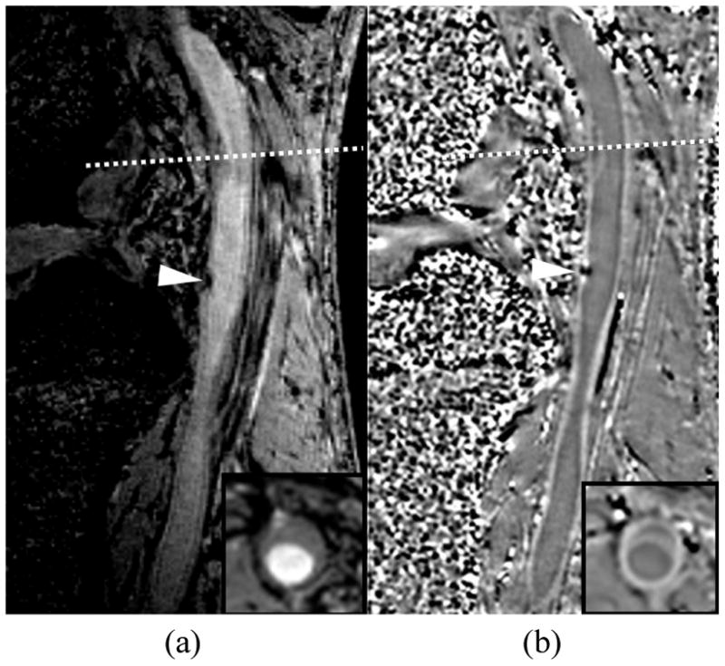
Susceptibility weighted image of a femoral artery showing a) the magnitude image and b) the phase image. Calcification (arrowhead) is dark on the magnitude image and causes a distinct phase difference on the phase image. The phase image also exhibits high wall contrast. The dotted line marks the location of the inset image.
Ultra-short T2 Species
Atherosclerotic tissues also exhibit components, such as lipoproteins and collagen, with T2 values too short to directly image using standard fast spin echo techniques. Ultra-short echo time (UTE) imaging techniques have been introduced to obtain signal from species with T2 values well under 1 ms using specialized slice selection techniques and radial k-space trajectories [26]. Du et al. [27] used a spiral trajectory to image normal carotid artery walls with a UTE sequence. Herzka et al. [28] demonstrated the ability to obtain variable signals within calcified regions of carotid atherosclerotic specimens imaged ex vivo with a UTE protocol.
Magnetization transfer is another means of imaging species with ultra-short T2 values. Magnetization transfer refers to the exchange of magnetization between bound protons (typically associated with proteins) that have ultra-short T2 and free protons with long T2. The short T2 value of the bound fraction leads to spectral broadening that allows an off-resonance RF pulse to saturate the bound proton magnetization. Magnetization transfer then leads to a fractional reduction of magnetization in the free pool, referred to as the “magnetization transfer ratio,” that depends on the size of the bound pool and the rate of transfer to the free pool. Differences in magnetization transfer have been reported between lipid-rich and fibrous regions of atherosclerotic plaques imaged ex vivo [29-31].
Diffusion and Perfusion
A final source of novel contrast mechanisms within plaques is the microscopic structure of the plaque components. Components can be organized, such as the laminar collagen of the fibrous cap, or amorphous as in the necrotic core. Fibrous regions can be dense or loose. Plaque regions can have a rich blood supply arising from the vasa vasorum or be relatively avascular. Thus, macroscopic imaging techniques that reveal this microscopic structure can be helpful for plaque characterization.
One such technique is diffusion weighted imaging (DWI), in which gradient pulses are applied that dephase spins in proportion to the rate of water diffusion. Regions with smaller diffusion coefficients undergo less dephasing and appear brighter on the resulting DWI image. In direct measurements of the diffusion coefficient, Toussaint et al. [32] showed that necrotic core regions of plaque have significantly lower diffusion coefficients than fibrous regions. Clarke et al. [33] showed that this property leads to significantly higher DWI intensities for necrotic cores compared to other plaque regions in carotid endarterectomy specimens scanned ex vivo. In ex vivo experiments, DWI proved better then T2-weighted images at distinguishing lipid and fibrous regions [34]. However, DWI suffers from long scan times and considerable motion sensitivity and may not be suitable for in vivo imaging of pulsing atherosclerotic vessels.
Another technique that relies on molecular transport for contrast is perfusion imaging, which quantifies the entry and extravasation of intravenously injected contrast agents into the plaque. Kinetic modeling of the signal variations due to contrast agent uptake can quantify biological properties such as the fractional plasma volume (vp) and transfer constant (Ktrans). Kerwin et al. [35] used this approach to construct “vasa vasorum images” that color code plaque regions according to the estimated vp and Ktrans (Fig. 2). In histological comparisons, in vivo measurements of vp and Ktrans in carotid arteries have been shown to correlate with plaque inflammatory features including neovascularity and macrophage content [9,10]. Recently, Chen et al. [36] showed that average Ktrans is significantly different among major plaque components.
Figure 2.
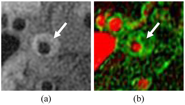
Vasa vasorum image of a carotid artery showing a) corresponding T1-weighted image, b) vasa vasorum image with vp mmapped to the red channel (full red corresponds to100%) and Ktrans mapped to the green channel (full green corresponds to 0.2 min-1). Arrow indicates eccentric plaque with high Ktrans.
Imaging Technology
In addition to providing adequate contrast between components, another key imaging challenge for assessing plaque features associated with biomechanical vulnerability is the spatial resolution of the resultant images. The most sought after feature is the thickness of the fibrous cap overlaying the thrombogenic necrotic core. Histological studies have used a cap thickness of 65 microns as a cutoff between stable and high-risk coronary plaques [37], which is well beyond resolutions on the order of 1 mm that are typically achieved in coronary artery MRI. In carotid arteries, cutoff values for high risk of rupture were found to be a minimal cap thickness of 200 microns and average thickness of 500 microns [38], values that are at least within reach of the typical spatial resolution of 500-600 microns used in carotid imaging. In carotids, however, even measurements of total wall thickness can be subject to considerable bias due to obliquity of the artery wall coupled with the finite image plane thickness, typically 2-3 mm [39]. Thus, considerable effort has been dedicated to improving resolution in-plane and reducing effective slice thickness. These efforts are inherently tied to considerations of signal-to-noise ratio, imaging time for large matrix acquisitions, and spatial coverage.
High-Field MRI
The increasing availability of 3 Tesla field strength scanners is considered to be a tremendous opportunity for improved vessel wall imaging. The doubling of field strength over common 1.5 Tesla scanners imparts a theoretical doubling of SNR that can be used to increase resolution and/or reduce imaging time. Experimentally, the achievable SNR improvement in carotid imaging was found to be 1.5 – 1.8 times, depending on sequence type [11]. Similar improvements were found in the aorta and shown to permit parallel imaging at 3 Tesla with an acceleration factor of 3 without a loss in SNR compared to non-accelerated imaging at 1.5 Tesla [16].
Higher field strength also has the potential to alter image contrast through changes in tissue magnetization parameters. However, in reviews of paired images taken with 1.5 and 3 Tesla field strengths, both manual outlining and an automatic classifier revealed no major differences in the detection or size measurement of plaque components [12,13]. Slight increases in the apparent size of calcifications and variations in hemorrhage appearance were observed at 3 Tesla, likely due to the increased susceptibility at higher field strength.
Higher field strengths above and beyond 3 Tesla may lead to further improvements in SNR. In vivo imaging of carotid atherosclerosis was recently demonstrated at 7 Tesla [40]. At these ultra-high fields, further changes in image contrast and susceptibility are apparent (Fig. 3). Thus, the relative merits of ultra-high field strengths require further investigation.
Figure 3.
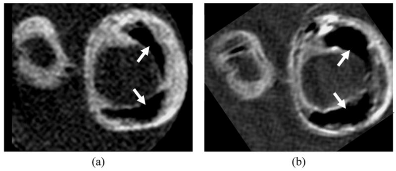
Matched cross sections of a carotid endarterectomy specimen imaged on a) 3 Tesla and b) 7 Tesla whole body scanners. At 7 Tesla, the specimen exhibits an apparent increase in the size of calcifications (arrows), more conspicuous variations in wall contrast, and overall higher signal-to-noise ratio.
3D MRI
Another strategy for improving SNR and resolution is to use 3D acquisition protocols. The use of phase encoding rather than slice selection to establish position in the third dimension permits isotropic or nearly isotropic image resolution while maintaining or increasing SNR. For example, Balu et al. [41] compared 2D and 3D protocols with fundamental resolutions of 0.6 × 0.6 × 2 mm and 0.6 × 0.6 × 1 mm, respectively. Despite the improved resolution, the 3D sequence retained similar and slightly higher SNR compared to the 2D sequence.
Although this result is encouraging, 2D acquisitions currently remain the standard for many plaque imaging sequences. 3D imaging is widely used for bright-blood acquisitions [17] and in inversion recovery sequences for detecting hemorrhage [7,42], but these approaches use gradient echo acquisitions that yield inferior vessel wall conspicuity compared to FSE acquisitions. For 3D imaging, however, FSE sequences suffer from long imaging times, high motion sensitivity, and difficulties with flow suppression in black-blood acquisitions. To address these issues, Crowe et al. [43] proposed a 3D FSE sequence with DIR blood suppression and navigator detection of swallowing. Koktzoglou and Li [44] proposed the use of steady-state free precession (SSFP) imaging with use of navigators to detect swallowing and a diffusion preparation for blood suppression in an isotropic 0.6 mm resolution 3D acquisition. The related motion sensitized driven equilibrium (MSDE) technique for blood suppression [45] has also been investigated for use in a 3D protocol because it does not depend on inflow for blood suppression [46]. Mitigation of swallowing artifacts was also proposed by Chan et al. [47] using an electrical signal induced by motion of a coil placed on the neck to reject data acquired during swallowing. If the challenges of 3D imaging of artery walls can be overcome, 3D imaging also offers potential time efficiencies for certain imaging geometries. For example, Zhang et al. [48] showed a nearly 75% reduction in imaging time for a long course of the femoral arteries by orienting a 3D slab along the axis of the artery and reformatting the result into the axial plane. This efficiency has also led Chung et al. [49] to propose whole-body plaque imaging in which 3D vessel wall imaging is performed at 4 separate imaging stations within 1 hour.
Coils
In addition to imaging sequences, hardware and particularly coils play an important role in atherosclerosis imaging. Thus coil design has been an area of significant effort [50-53]. The recent push for increased numbers of receivers in MRI scanners has opened the door for coil designs with large numbers of elements [54]. For example, the use of an 8-element carotid phased array was shown to increase SNR by more than 60% compared to a 4-element version [55]. In addition, coil placement is a key concern, especially for deep arteries, ill-suited for small surface coils. This has led to the introduction of transesophageal coils [56] and intravascular coils [57-59]. Design of coils for parallel imaging has not been addressed for atherosclerosis imaging because of the SNR-limited nature of the acquisitions. Nevertheless, as higher fields and 3D imaging yield improved SNR, parallel imaging will likely become a consideration in coil design for vessel wall imaging.
Coronary Wall Imaging
The imaging technology described above is generally applicable to multiple vessels, but the coronary arteries present special challenges that have led to unique technologies specific to coronary arteries. Several of the challenges include the need to overcome cardiac and respiratory motion, the generally large area of the chest compared to the small size of the arteries, a tortuous vessel course, and difficulties with blood suppression. In early efforts [19,20], 2D FSE cross-sectional images aligned using coronary MRA showed the ability to obtain black-blood wall images. More recently, 3D gradient echo or SSFP sequences aligned with the long axis of the vessel have become more common [20,21]. In addition, use of radial or spiral acquisitions [22] improves temporal performance and reduces motion sensitivity. The long scan times are accommodated by the use of navigator gating and by acquiring data during diastasis, a relatively long window during which coronary arteries are nearly stationary. Because the 3D volume acquisitions do not accommodate standard techniques for blood suppression, specialized sequences have been suggested using localized inversion pulses [60] or MSDE blood suppression that does not rely on blood inflow (Fig. 4) [61].
Figure 4.
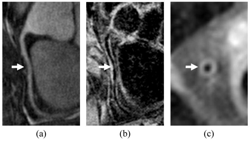
Coronary wall imaging showing a) MRA of right coronary artery, b) longitudinal vessel wall image with thickening indicated by arrow, c) cross sectional vessel wall image. Blood suppression was accomplished using motion-sensitized driven equilibrium, which does not depend on inflow over the long course of the artery.
Biomechanical Analysis of Plaque
The overall goal of plaque imaging is to identify specific features of the plaque that are most important for predicting risk of clinical events or evaluating plaque progression. Histological and MRI studies [3-6] have pinpointed a number of key features – thin fibrous caps, large lipid cores, presence of intraplaque hemorrhage – that share a common biomechanical thread. Thus, the definition of the vulnerable plaque may not arise from a single morphological feature, but instead from the biomechanical implications of all features. Furthermore, numerous studies have linked biomechanical forces to the pathogenesis of atherosclerotic plaque [62-68], implying that biomechanical analyses may reveal a predisposition for future vulnerable plaque development. Thus, techniques are needed to translate basic morphological images of the vessel wall into biomechanical assessments of stresses within the plaque.
The mechanical factors of interest derive from two primary mechanical forces of hemodynamic origin: fluid wall shear stress and tensile stress. The shear stress is the frictional force per unit area acting on the endothelium, in the direction of the flow. Several studies have shown that plaque development occurs in regions of low wall shear stress or regions with marked temporal fluctuations in the direction of shear stress, whereas high unidirectional shear stress may exert a protective effect against the induction of lesions [62-65]. Recent studies have suggested that shear stress forces also play a role in the biological processes that destabilize the fibrous cap, leading to a rupture-prone, vulnerable plaque. In particular, it has been proposed that endothelial cells react to shear stress modifying the balance between cap-reinforcing extracellular matrix synthesis by smooth-muscle cells and extracellular matrix degradation by metalloproteinases secreted by infiltrating macrophages [62].
The tensile stress, on the other hand, is the normal component of the stress tensor that develops along the arterial wall in response to the mechanical loading exerted by the transmural pressure and is the source of the mechanical strain exhibited by the arterial wall components. Richardson et al [66] observed that tensile stresses were higher in regions where fibrous cap rupture was reported to occur most frequently (the junction of the cap with the adjacent normal intima). Cheng et al [67] found that the location of cap rupture was not always the area of greatest stress in an individual lesion, suggesting that local variations in plaque strength may determine the rupture site. However, not only the local weakening of the fibrous cap, but also the failure of the biological tissues to compensate the effect of the increased tensile stress [68] could be a major factor in plaque rupture.
Computational Modeling
Most efforts to assess plaque mechanics that have involved MRI depend on the use of computational models derived from vessel wall morphology extracted from images. Computational fluid dynamics (CFD) provides a means to derive the geometry and flow boundary conditions from medical imaging data. Modeling blood flow using patient-specific vessel geometry and blood flow conditions obtained from medical imaging is a multi-step task, involving geometric reconstruction from the segmented image, mesh generation, acquisition and/or definition of boundary conditions, and numerical calculation (Fig. 5).
Figure 5.
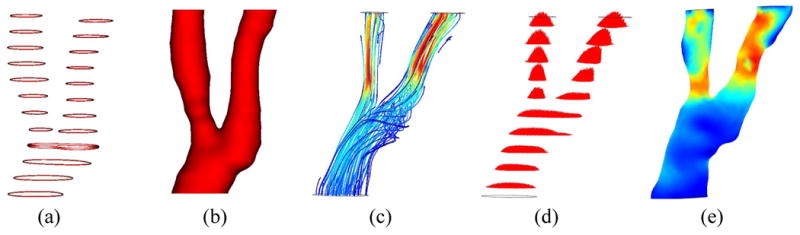
Illustration of computational fluid dynamics for assessment of wall shear stress showing a) lumen contours extracted from cross-sectional MRI, b) reconstructed lumen surface, c) estimated flow pattern depicted using streamlines, d) estimated flow profiles in each cross-section, e) resultant wall shear stress map. In the map, low shear stress is shown in blue and high stress is shown in red.
Black blood MRI has been used to depict and render the luminal geometry in CFD studies of carotid atherosclerosis [69-71]. Groen et al. [72] described a case where an ulcer developed at a location exhibiting high shear stress prior to the ulceration. MRI-based CFD calculations have proven to be reasonably reproducible except for the bifurcation apex area where wall shear stresses are usually high [73,74]. Models have been built to assess the effect of inter-individual geometrical variations of the carotid bifurcation on blood flow patterns and geometrical surrogates of its exposure to disturbed flow have been proposed [75-77]. Such geometrical variations have a greater effect on the resulting wall shear stress patterns than variations in the assumed inlet velocity profile [78] or in the rheological blood properties [79]; thus, more effort should be made on incorporating a larger section of the common carotid artery when studying the disease in this arterial bifurcation.
In the aforementioned CFD models, rigid walls are commonly used under the assumption that the effect of wall motion on flow patterns, in particular on wall shear stress, is minimal in diseased arteries. However, to better understand the role of hemodynamics in plaque progression and rupture, the mechanical response of the arterial wall to the tensile stresses needs to be modeled. In fact, much work has been done to incorporate the mechanical behavior of the atherosclerotic plaque coupling flow and wall mechanics in the image-based numerical simulations using fluid-structure interaction (FSI) models (Fig. 6) [80-84]. These FSI models require knowledge of the presence and size of the different plaque constituents within the wall (e.g., fibrous cap, lipid pool, etc) and of their material properties. Due to the lack of in vivo measurements of the tissue mechanical properties, different models have been proposed [85] and Williamson et al showed a low sensitivity of the predicted stress levels to the proposed models [86]. However, differences in stress due to hypothetical changes in the position of the necrotic core [87] suggest that accurate depiction of the component morphologies is critical.
Figure 6.
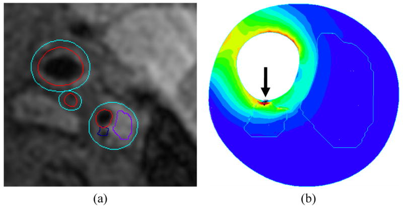
Illustration of fluid structure interaction model of a carotid plaque showing a) plaque regions extracted from cross sectional MRI and b) corresponding stress map within the wall. A high-stress region (arrow) is associated with a small juxtaluminal calcification. In the map, low stress is shown in blue and high stress is shown in red.
Direct Imaging
MRI also affords the opportunity to directly characterize arterial flow patterns, as well as measure blood flow velocity using phase-contrast MRI (PC-MRI) [88-91]. The velocity information provided by PC-MRI has been used to compute wall shear stress maps along different arterial segments, using interpolation techniques to overcome the relatively low spatial resolution [92-94]. However, the interpolation method used in some of these techniques is based on assumptions about the blood flow, such as having a parabolic profile, that are an invalid approximation when dealing with the complex flow that characterizes diseased arteries. In fact, some authors have compared the numerically computed flow patterns with PC-MRI velocity measurements in healthy and stenotic carotid artery models [95-97]. They found qualitative agreement between both techniques except at the regions where the flow was most disturbed: at the bulb in the healthy carotid and at post-stenotic region in the diseased model. There have been some attempts to increase the spatial resolution without reducing the signal-to-noise ratio by varying the velocity encoding along the cardiac cycle [98] but, again, the method was limited to arterial segments with no disturbed or complicated flow patterns.
Finally, MRI techniques exist to directly measure strain [99,100] in tissue that can potentially be used to replace, validate, or augment FSI models of vessel wall strain. Lin et al. [99] recently demonstrated that circumferential strain measured by displacement encoding with stimulated echoes (DENSE) agreed with CINE measurements of changes in lumen circumference in normal carotid arteries. Such strain imaging approaches, however, may not have the required resolution to measure other components of strain, most notably radial strain.
Discussion
Considerable work has been performed to advance the state of the art in vessel wall imaging. These activities have led to viable approaches for imaging atherosclerotic plaque in the carotid arteries [4-13], femoral arteries [14,15], aorta [16-18], cerebral arteries [101], and coronaries [19-22]. Because each vessel presents its own unique challenges, the extent to which each of these technologies applies to each artery varies.
Overview by Artery
By far the most activity in vessel wall MRI has focused on the carotid arteries. Virtually all MRI-guided biomechanical analyses in the presence of plaque have been performed using carotid arteries. Also, novel contrast mechanisms have been tested first using the carotid arteries because of the availability of endarterectomy specimens for ex vivo imaging and histological comparison. High-field MRI is considered to be well-suited to the carotids as are specialized surface coil designs. Although 3D acquisition techniques have been proposed for the carotid arteries, 2D imaging remains common, given the compact, localized nature of carotid disease.
The coronary arteries have also received considerable attention. However, the imaging challenge associated with viewing even basic morphology of the coronary wall has led to most efforts being directed toward specialized sequences for morphological imaging. In the event that MRI-based compositional analyses become possible for coronary arteries, the unique contrast aspects of these sequences will need to be understood. In regards to field strength, preliminary studies have established the feasibility of coronary wall imaging at 3T [102,103], but whether the benefits of higher fields will outweigh the increased field inhomogeneity and SAR considerations remains uncertain.
In arteries such as the femorals and aorta, 3D imaging is emerging as an important tool that allows time-efficient, extended coverage. These arteries may also be especially well suited for some of the novel contrast mechanisms. Specifically, the femoral arteries are a good target for SWI because they exhibit comparably slow blood flow and tend to be heavily calcified. The aorta is a common target for shear stress analysis because its large size is compatible with accurate characterization of blood velocities by PC-MRI.
Other Advanced Technologies
Although this review attempted to be comprehensive in examining three core technology areas for vessel wall imaging, other core areas exist. Most notably, targeted contrast agents are being developed to reveal specific molecular aspects of atherosclerotic plaque, as previously reviewed in this journal [104]. These technologies are generally limited to animal research at this time, with the exception of USPIOs that target macrophages in humans [105]. In addition, all of the techniques described here require advanced image processing applications to extract the relevant information regarding plaque morphology [106].
Conclusion
Given the significant activity in the area of vessel wall MRI, considerable new technology is likely to be developed in the coming years. The ability to accurately identify, measure, and model plaque composition and mechanics will enable the biomechanical theory of plaque rupture to be tested in prospective studies. Vessel wall imaging will also be increasingly applied beyond the carotid arteries to other clinically relevant areas of disease.
Acknowledgments
The authors thank the following individuals for consultations on the content and/or contribution of images: Mark Haacke (Figure 1), Jarett Berry (Figure 3), Jinnan Wang (Figure 4), Dalin Tang (Figure 6), Chun Yuan, and Niranjan Balu.
References
- 1.Falk E, Shah PK, Fuster V. Coronary plaque disruption. Circulation. 1995;92:657–671. doi: 10.1161/01.cir.92.3.657. [DOI] [PubMed] [Google Scholar]
- 2.Glagov S, Weisenberg E, Zarins CK, et al. Compensatory enlargement of human atherosclerotic coronary arteries. N Engl J Med. 1987;316:1371–1375. doi: 10.1056/NEJM198705283162204. [DOI] [PubMed] [Google Scholar]
- 3.Virmani R, Burke AP, Farb A, Kolodgie FD. Pathology of the vulnerable plaque. J Am Coll Cardiol. 2006;47(8 Suppl):C13–C18. doi: 10.1016/j.jacc.2005.10.065. [DOI] [PubMed] [Google Scholar]
- 4.Saam T, Ferguson MS, Yarnykh VL, et al. Quantitative evaluation of carotid plaque composition by in vivo MRI. Arterioscler Thromb Vasc Biol. 2005;25:234–239. doi: 10.1161/01.ATV.0000149867.61851.31. [DOI] [PubMed] [Google Scholar]
- 5.Chu B, Kampschulte A, Ferguson MS, et al. Hemorrhage in the atherosclerotic carotid plaque: a high-resolution MRI study. Stroke. 2004;35:1079–1084. doi: 10.1161/01.STR.0000125856.25309.86. [DOI] [PubMed] [Google Scholar]
- 6.Moody AR, Murphy RE, Morgan PS, et al. Characterization of complicated carotid plaque with magnetic resonance direct thrombus imaging in patients with cerebral ischemia. Circulation. 2003;107:3047–3052. doi: 10.1161/01.CIR.0000074222.61572.44. [DOI] [PubMed] [Google Scholar]
- 7.Zhu DC, Ferguson MS, DeMarco JK. An optimized 3D inversion recovery prepared fast spoiled gradient recalled sequence for carotid plaque hemorrhage imaging at 3.0 T. Magn Reson Imaging. 2008;26:1360–1366. doi: 10.1016/j.mri.2008.05.002. [DOI] [PubMed] [Google Scholar]
- 8.Raman SV, Winner MW, 3rd, Tran T, et al. In vivo atherosclerotic plaque characterization using magnetic susceptibility distinguishes symptom-producing plaques. JACC Cardiovasc Imaging. 2008;1:49–57. doi: 10.1016/j.jcmg.2007.09.002. [DOI] [PMC free article] [PubMed] [Google Scholar]
- 9.Kerwin W, Hooker A, Spilker M, et al. Quantitative MRI analysis of neovasculature volume in carotid atherosclerotic plaque. Circulation. 2003;107:851–856. doi: 10.1161/01.cir.0000048145.52309.31. [DOI] [PubMed] [Google Scholar]
- 10.Kerwin WS, O'Brien KD, Ferguson MS, et al. Inflammation in Carotid Atherosclerotic Plaque is Associated with Elevated Neovasculature and Permeability: A Dynamic Contrast-Enhanced MRI Study. Radiol. 2006;241:459–468. doi: 10.1148/radiol.2412051336. [DOI] [PMC free article] [PubMed] [Google Scholar]
- 11.Yarnykh VL, Terashima M, Hayes CE, et al. Multicontrast black-blood MRI of carotid arteries: comparison between 1.5 and 3 tesla magnetic field strengths. J Magn Reson Imaging. 2006;23:691–698. doi: 10.1002/jmri.20562. [DOI] [PubMed] [Google Scholar]
- 12.Underhill HR, Yarnykh VL, Hatsukami TS, et al. Carotid plaque morphology and composition: initial comparison between 1.5- and 3.0-T magnetic field strengths. Radiology. 2008;248:550–560. doi: 10.1148/radiol.2482071114. [DOI] [PMC free article] [PubMed] [Google Scholar]
- 13.Kerwin WS, Liu F, Yarnykh V, et al. Signal features of the atherosclerotic plaque at 3.0 Tesla versus 1.5 Tesla: impact on automatic classification. J Magn Reson Imaging. 2008;28:987–995. doi: 10.1002/jmri.21529. [DOI] [PMC free article] [PubMed] [Google Scholar]
- 14.Isbell DC, Meyer CH, Rogers WJ, et al. Reproducibility and reliability of atherosclerotic plaque volume measurements in peripheral arterial disease with cardiovascular magnetic resonance. J Cardiovasc Magn Reson. 2007;9:71–76. doi: 10.1080/10976640600843330. [DOI] [PMC free article] [PubMed] [Google Scholar]
- 15.Kramer H, Michaely HJ, Reiser MF, Schoenberg SO. Peripheral magnetic resonance angiography at 3.0 T. Top Magn Reson Imaging. 2007;18:135–138. doi: 10.1097/RMR.0b013e3180cac73b. [DOI] [PubMed] [Google Scholar]
- 16.Maroules CD, McColl R, Khera A, Peshock RM. Assessment and reproducibility of aortic atherosclerosis magnetic resonance imaging: impact of 3-Tesla field strength and parallel imaging. Invest Radiol. 2008;43:656–662. doi: 10.1097/RLI.0b013e318181538a. [DOI] [PubMed] [Google Scholar]
- 17.Markl M, Dudler P, Fydrychowicz A, et al. Optimized 3D bright blood MRI of aortic plaque at 3 T. Magn Reson Imaging. 2008;26:330–336. doi: 10.1016/j.mri.2007.08.010. [DOI] [PubMed] [Google Scholar]
- 18.Momiyama Y, Fayad ZA. Aortic plaque imaging and monitoring atherosclerotic plaque interventions. Top Magn Reson Imaging. 2007;18:349–355. doi: 10.1097/rmr.0b013e31815a0e5d. [DOI] [PubMed] [Google Scholar]
- 19.Fayad ZA, Fuster V, Fallon JT, et al. Noninvasive in vivo human coronary artery lumen and wall imaging using black-blood magnetic resonance imaging. Circulation. 2000;102:506–510. doi: 10.1161/01.cir.102.5.506. [DOI] [PubMed] [Google Scholar]
- 20.Botnar RM, Stuber M, Kissinger KV, et al. Noninvasive coronary vessel wall and plaque imaging with magnetic resonance imaging. Circulation. 2000;102:2582–2587. doi: 10.1161/01.cir.102.21.2582. [DOI] [PubMed] [Google Scholar]
- 21.Kim WY, Stuber M, Börnert P, et al. Three-dimensional black-blood cardiac magnetic resonance coronary vessel wall imaging detects positive arterial remodeling in patients with nonsignificant coronary artery disease. Circulation. 2002;106:296–299. doi: 10.1161/01.cir.0000025629.85631.1e. [DOI] [PubMed] [Google Scholar]
- 22.Katoh M, Spuentrup E, Buecker A, et al. MR coronary vessel wall imaging: comparison between radial and spiral k-space sampling. J Magn Reson Imaging. 2006;23:757–762. doi: 10.1002/jmri.20569. [DOI] [PubMed] [Google Scholar]
- 23.Zhu DC, Ota H, Vu AT, DeMarco JK. An Optimized 3D Spoiled Gradient for Hemorrhage Assessment Using INversion Recovery and Multiple Echoes (3D SHINE) for Carotid Plaque Imaging. Proc. ISMRM 17th Scientific Meeting and Exhibition; Honolulu. 2009. p. 606. [DOI] [PubMed] [Google Scholar]
- 24.Haacke EM, Xu Y, Cheng YC, Reichenbach JR. Susceptibility weighted imaging (SWI) Magn Reson Med. 2004;52:612–618. doi: 10.1002/mrm.20198. [DOI] [PubMed] [Google Scholar]
- 25.Yang Q, Liu J, Barnes S, et al. Imaging the Vessel Wall in Major Peripheral Arteries Using Susceptibility Weighted Imaging: Visualizing Calcifications. Proc. ISMRM 17th Scientific Meeting and Exhibition; Honolulu. 2009. p. 608. [DOI] [PMC free article] [PubMed] [Google Scholar]
- 26.Gatehouse PD, Bydder GM. Magnetic resonance imaging of short T2 components in tissue. Clin Radiol. 2003;58:1–19. doi: 10.1053/crad.2003.1157. [DOI] [PubMed] [Google Scholar]
- 27.Du J, Bydder M, Takahashi AM, Chung CB. Two-dimensional ultrashort echo time imaging using a spiral trajectory. Magn Reson Imaging. 2008;26:304–312. doi: 10.1016/j.mri.2007.08.005. [DOI] [PubMed] [Google Scholar]
- 28.Herzka DA, Rahmer J, Nezafat R, et al. High resolution ultra-short TE imaging of ex vivo human carotid plaques correlates with CT. Proc. ISMRM 16th Scientific Meeting and Exhibition; Toronto. 2008. p. 962. [Google Scholar]
- 29.Pachot-Clouard M, Vaufrey F, Darrasse L, Toussainti JF. Magnetization transfer characteristics in atherosclerotic plaque components assessed by adapted binomial preparation pulses. MAGMA. 1998;7:9–15. doi: 10.1007/BF02592251. [DOI] [PubMed] [Google Scholar]
- 30.Rogers WJ, Prichard JW, Hu YL, et al. Characterization of signal properties in atherosclerotic plaque components by intravascular MRI. Arterioscler Thromb Vasc Biol. 2000;20:1824–1830. doi: 10.1161/01.atv.20.7.1824. [DOI] [PubMed] [Google Scholar]
- 31.Kerwin W, Ferguson M, Small R, et al. Magnetization transfer as a contrast enhancing mechanism in magnetic resonance images of human atherosclerotic plaques. Atherosclerosis. 2000;151:25. [Google Scholar]
- 32.Toussaint JF, Southern JF, Fuster V, Kantor HL. Water diffusion properties of human atherosclerosis and thrombosis measured by pulse field gradient nuclear magnetic resonance. Arterioscler Thromb Vasc Biol. 1997;17:542–546. doi: 10.1161/01.atv.17.3.542. [DOI] [PubMed] [Google Scholar]
- 33.Clarke SE, Hammond RR, Mitchell JR, Rutt BK. Quantitative assessment of carotid plaque composition using multicontrast MRI and registered histology. Magn Reson Med. 2003;50:1199–1208. doi: 10.1002/mrm.10618. [DOI] [PubMed] [Google Scholar]
- 34.Qiao Y, Ronen I, Viereck J, et al. Identification of atherosclerotic lipid deposits by diffusion-weighted imaging. Arterioscler Thromb Vasc Biol. 2007;27:1440–1446. doi: 10.1161/ATVBAHA.107.141028. [DOI] [PMC free article] [PubMed] [Google Scholar]
- 35.Kerwin WS, Oikawa M, Yuan C, et al. MR imaging of adventitial vasa vasorum in carotid atherosclerosis. Magn Reson Med. 2008;59:507–514. doi: 10.1002/mrm.21532. [DOI] [PubMed] [Google Scholar]
- 36.Chen H, Cai J, Zhao X, et al. Localized measurement of atherosclerotic plaque inflammatory burden with dynamic contrast-enhanced MRI. Proc. ISMRM 17th Scientific Meeting and Exhibition; Honolulu. 2009. p. 1908. [DOI] [PubMed] [Google Scholar]
- 37.Burke AP, Farb A, Malcom GT, et al. Coronary risk factors and plaque morphology in men with coronary disease who died suddenly. N Engl J Med. 1997;336:1276–1282. doi: 10.1056/NEJM199705013361802. [DOI] [PubMed] [Google Scholar]
- 38.Redgrave JN, Gallagher P, Lovett JK, Rothwell PM. Critical cap thickness and rupture in symptomatic carotid plaques: the oxford plaque study. Stroke. 2008;39:1722–1729. doi: 10.1161/STROKEAHA.107.507988. [DOI] [PubMed] [Google Scholar]
- 39.Antiga L, Wasserman BA, Steinman DA. On the overestimation of early wall thickening at the carotid bulb by black blood MRI, with implications for coronary and vulnerable plaque imaging. Magn Reson Med. 2008;60:1020–1028. doi: 10.1002/mrm.21758. [DOI] [PubMed] [Google Scholar]
- 40.Kraff O, Maderwald S, Hahn S, et al. In-vivo plaque imaging of the carotid arteries at 7 Tesla: First results. Proc. ISMRM 16th Scientific Meeting and Exhibition; Toronto. 2008. p. 1995. [Google Scholar]
- 41.Balu N, Chu B, Hatsukami TS, et al. Comparison between 2D and 3D high-resolution black-blood techniques for carotid artery wall imaging in clinically significant atherosclerosis. J Magn Reson Imaging. 2008;27:918–924. doi: 10.1002/jmri.21282. [DOI] [PMC free article] [PubMed] [Google Scholar]
- 42.Bitar R, Moody AR, Leung G, et al. In vivo 3D high-spatial-resolution MR imaging of intraplaque hemorrhage. Radiology. 2008;249:259–267. doi: 10.1148/radiol.2491071517. [DOI] [PubMed] [Google Scholar]
- 43.Crowe LA, Keegan J, Gatehouse PD, et al. 3D volume-selective turbo spin echo for carotid artery wall imaging with navigator detection of swallowing. J Magn Reson Imaging. 2005;22:583–588. doi: 10.1002/jmri.20424. [DOI] [PubMed] [Google Scholar]
- 44.Koktzoglou I, Li D. Submillimeter isotropic resolution carotid wall MRI with swallowing compensation: imaging results and semiautomated wall morphometry. J Magn Reson Imaging. 2007;25:815–823. doi: 10.1002/jmri.20849. [DOI] [PubMed] [Google Scholar]
- 45.Wang J, Yarnykh VL, Hatsukami T, et al. Improved suppression of plaque-mimicking artifacts in black-blood carotid atherosclerosis imaging using a multislice motion-sensitized driven-equilibrium (MSDE) turbo spin-echo (TSE) sequence. Magn Reson Med. 2007;58:973–981. doi: 10.1002/mrm.21385. [DOI] [PubMed] [Google Scholar]
- 46.Balu N, Yarnykh V, Chu B, et al. Carotid Plaque Assessment Using Fast 3D Isotropic-Resolution Black-Blood MRI. Proc. ISMRM 17th Scientific Meeting and Exhibition; Honolulu. 2009. p. 1826. [DOI] [PMC free article] [PubMed] [Google Scholar]
- 47.Chan CF, Gatehouse PD, Hughes R, et al. Novel technique used to detect swallowing in volume-selective turbo spin-echo (TSE) for carotid artery wall imaging. J Magn Reson Imaging. 2009;29:211–216. doi: 10.1002/jmri.21607. [DOI] [PubMed] [Google Scholar]
- 48.Zhang Z, Fan Z, Carroll T, et al. Three-Dimensional T2-Weighted TSE MRI of the Human Femoral Arterial Vessel Wall at 3.0 Tesla. Proc. ISMRM 17th Scientific Meeting and Exhibition; Honolulu. 2009. p. 3838. [DOI] [PMC free article] [PubMed] [Google Scholar]
- 49.Chung YC, Mihai G, Simonetti OP, et al. Whole Body Three Dimensional Plaque Imaging. Proc. ISMRM 17th Scientific Meeting and Exhibition; Honolulu. 2009. p. 1823. [Google Scholar]
- 50.Hayes CE, Mathis CM, Yuan C. Surface coil phased arrays for high-resolution imaging of the carotid arteries. J Magn Reson Imaging. 1996;6:109–112. doi: 10.1002/jmri.1880060121. [DOI] [PubMed] [Google Scholar]
- 51.Ouhlous M, Lethimonnier F, Dippel DW, et al. Evaluation of a dedicated dual phased-array surface coil using a black-blood FSE sequence for high resolution MRI of the carotid vessel wall. J Magn Reson Imaging. 2002;15:344–351. doi: 10.1002/jmri.10067. [DOI] [PubMed] [Google Scholar]
- 52.Liffers A, Quick HH, Herborn CU, et al. Geometrical optimization of a phased array coil for high-resolution MR imaging of the carotid arteries. Magn Reson Med. 2003;50:439–443. doi: 10.1002/mrm.10526. [DOI] [PubMed] [Google Scholar]
- 53.Ouhlous M, Moelker A, Flick HJ, et al. Quadrature coil design for high-resolution carotid artery imaging scores better than a dual phased-array coil design with the same volume coverage. J Magn Reson Imaging. 2007;25:1079–1084. doi: 10.1002/jmri.20894. [DOI] [PubMed] [Google Scholar]
- 54.Hadley JR, Roberts JA, Goodrich KC, et al. Relative RF coil performance in carotid imaging. Magn Reson Imaging. 2005;23:629–639. doi: 10.1016/j.mri.2005.04.009. [DOI] [PubMed] [Google Scholar]
- 55.Balu N, Yarnykh V, Hayes C, et al. Improvements in spatial resolution using a novel 8-element carotid phased array coil at 3T. Proc ISMRM 16th Scientific Meeting and Exhibition; Toronto. 2008. p. 952. [Google Scholar]
- 56.Steen H, Warren WP, Desai M, et al. Combined transesophageal and surface MRI provides optimal imaging in aortic atherosclerosis. J Cardiovasc Magn Reson. 2004;6:909–916. doi: 10.1081/jcmr-200036202. [DOI] [PubMed] [Google Scholar]
- 57.Rogers WJ, Prichard JW, Hu YL, et al. Characterization of signal properties in atherosclerotic plaque components by intravascular MRI. Arterioscler Thromb Vasc Biol. 2000;20:1824–1830. doi: 10.1161/01.atv.20.7.1824. [DOI] [PubMed] [Google Scholar]
- 58.Botnar RM, Bücker A, Kim WY, et al. Initial experiences with in vivo intravascular coronary vessel wall imaging. J Magn Reson Imaging. 2003;17:615–619. doi: 10.1002/jmri.10291. [DOI] [PubMed] [Google Scholar]
- 59.Larose E, Yeghiazarians Y, Libby P, et al. Characterization of human atherosclerotic plaques by intravascular magnetic resonance imaging. Circulation. 2005;112:2324–2331. doi: 10.1161/CIRCULATIONAHA.105.538942. [DOI] [PubMed] [Google Scholar]
- 60.Botnar RM, Kim WY, Börnert P, et al. 3D coronary vessel wall imaging utilizing a local inversion technique with spiral image acquisition. Magn Reson Med. 2001;46:848–854. doi: 10.1002/mrm.1268. [DOI] [PubMed] [Google Scholar]
- 61.Wang J, Gerretsen SC, Maki JH, et al. Robust and Time-Efficient Black Blood Coronary Vessel Wall Imaging at 3T Using IMSDE. Proc ISMRM 17th Scientific Meeting and Exhibition; Honolulu. 2009. p. 1895. [Google Scholar]
- 62.Cheng C, Tempel D, van Haperen R, et al. Atherosclerotic lesion size and vulnerability are determined by patterns of fluid shear stress. Circulation. 2006;113:2744–2753. doi: 10.1161/CIRCULATIONAHA.105.590018. [DOI] [PubMed] [Google Scholar]
- 63.Malek AM, Alper SL, Izumo S. Hemodynamic shear stress and its role in atherosclerosis. JAMA. 1999;282:2035–2042. doi: 10.1001/jama.282.21.2035. [DOI] [PubMed] [Google Scholar]
- 64.Caro CG. Discovery of the Role of Wall Shear in Atherosclerosis. Arterioscler Thromb Vasc Biol. 2009;29:158–161. doi: 10.1161/ATVBAHA.108.166736. [DOI] [PubMed] [Google Scholar]
- 65.Ku DN, Giddens DP, Zarins CK, Glagov S. Pulsatile flow and atherosclerosis in the human carotid bifurcation. Positive correlation between plaque location and low oscillating shear stress. Arteriosclerosis. 1985;5:293–302. doi: 10.1161/01.atv.5.3.293. [DOI] [PubMed] [Google Scholar]
- 66.Richardson PD, Davies MJ, Born GVR. Influence of plaque configuration and stress distribution on fissuring of coronary atherosclerotic plaques. Lancet. 1989;2:941–944. doi: 10.1016/s0140-6736(89)90953-7. [DOI] [PubMed] [Google Scholar]
- 67.Cheng GC, Loree HM, Kamm RD, et al. Distribution of circumferential stress in ruptured and stable atherosclerotic lesions. A structural analysis with histopathological correlation. Circulation. 1993;87:1179–1187. doi: 10.1161/01.cir.87.4.1179. [DOI] [PubMed] [Google Scholar]
- 68.Arroyo LH, Lee RT. Mechanisms of plaque rupture: mechanical and biologic interactions. Cardiovasc Res. 1999;41:369–375. doi: 10.1016/s0008-6363(98)00308-3. [DOI] [PubMed] [Google Scholar]
- 69.Steinman DA, Thomas JB, Ladak HM, et al. Reconstruction of carotid bifurcation hemodynamics and wall thickness using computational fluid dynamics and MRI. Magn Reson Med. 2002;47:149–159. doi: 10.1002/mrm.10025. [DOI] [PubMed] [Google Scholar]
- 70.Kaazempur-Mofrad MR, Isasi AG, Younis HF, et al. Characterization of the atherosclerotic carotid bifurcation using MRI, finite element modeling, and histology. Ann Biomed Eng. 2004;32:932–946. doi: 10.1023/b:abme.0000032456.16097.e0. [DOI] [PubMed] [Google Scholar]
- 71.Long Q, Xu XY, Ariff B, et al. Reconstruction of blood flow patterns in a human carotid bifurcation: A combined CFD and MRI study. J Magn Reson Imaging. 2000;11:299–311. doi: 10.1002/(sici)1522-2586(200003)11:3<299::aid-jmri9>3.0.co;2-m. [DOI] [PubMed] [Google Scholar]
- 72.Groen HC, Gijsen FJH, van der Lugt A, et al. Plaque rupture in the carotid artery is localized at the high shear stress region - A case report. Stroke. 2007;38:2379–2381. doi: 10.1161/STROKEAHA.107.484766. [DOI] [PubMed] [Google Scholar]
- 73.Glor FP, Long Q, Hughes AD, et al. Reproducibility study of magnetic resonance image-based computational fluid dynamics prediction of carotid bifurcation flow. Ann Biomed Eng. 2003;31:142–151. doi: 10.1114/1.1537694. [DOI] [PubMed] [Google Scholar]
- 74.Thomas JB, Milner JS, Rutt BK, Steinman DA. Reproducibility of image-based computational fluid dynamics models of the human carotid bifurcation. Ann Biomed Eng. 2003;31:132–141. doi: 10.1114/1.1540102. [DOI] [PubMed] [Google Scholar]
- 75.Zhao SZ, Ariff B, Long Q, et al. Inter-individual variations in wall shear stress and mechanical stress distributions at the carotid artery bifurcation of healthy humans. J Biomech. 2002;35:1367–1377. doi: 10.1016/s0021-9290(02)00185-9. [DOI] [PubMed] [Google Scholar]
- 76.Lee SW, Antiga L, Spence JD, Steinman DA. Geometry of the carotid bifurcation predicts its exposure to disturbed flow. Stroke. 2008;39:2341–2347. doi: 10.1161/STROKEAHA.107.510644. [DOI] [PubMed] [Google Scholar]
- 77.Thomas JB, Milner JS, Steinman DA. On the influence of vessel planarity on local hemodynamics at the human carotid bifurcation. Biorheology. 2002;39:443–448. [PubMed] [Google Scholar]
- 78.Moyle KR, Antiga L, Steinman DA. Inlet conditions for image-based CFD models of the carotid bifurcation: Is it reasonable to assume fully developed flow? J Biomech Eng. 2006;128:371–379. doi: 10.1115/1.2187035. [DOI] [PubMed] [Google Scholar]
- 79.Lee SW, Steinman DA. On the relative importance of rheology for image-based CFD models of the carotid bifurcation. J Biomech Eng. 2007;129:273–278. doi: 10.1115/1.2540836. [DOI] [PubMed] [Google Scholar]
- 80.Kock SA, Nygaard JV, Eldrup N, et al. Mechanical stresses in carotid plaques using MRI-based fluid-structure interaction models. J Biomech. 2008;41:1651–1658. doi: 10.1016/j.jbiomech.2008.03.019. [DOI] [PubMed] [Google Scholar]
- 81.Li ZY, Howarth S, Trivedi RA, et al. Stress analysis of carotid plaque rupture based on in vivo high resolution MRI. J Biomech. 2006;39:2611–2622. doi: 10.1016/j.jbiomech.2005.08.022. [DOI] [PubMed] [Google Scholar]
- 82.Zhao SZ, Xu XY, Collins MW. The numerical analysis of fluid-solid interactions for blood flow in arterial structures - Part 2: development of coupled fluid-solid algorithms. Proc Inst Mech Eng H. 1998;212:241–252. doi: 10.1243/0954411981534024. [DOI] [PubMed] [Google Scholar]
- 83.Tang DL, Yang C, Zheng J, et al. Quantifying effects of plaque structure and material properties on stress distributions in human atherosclerotic plaques using 3D FSI models. J Biomech Eng. 2005;127:1185–1194. doi: 10.1115/1.2073668. [DOI] [PMC free article] [PubMed] [Google Scholar]
- 84.Gao H, Long Q, Graves M, et al. Carotid arterial plaque stress analysis using fluid-structure interactive simulation based on in-vivo magnetic resonance images of four patients. J Biomech. 2009;42:1416–1423. doi: 10.1016/j.jbiomech.2009.04.010. [DOI] [PubMed] [Google Scholar]
- 85.Zhao SZ, Xu XY, Collins MW. The numerical analysis of fluid-solid interactions for blood flow in arterial structures - Part 1: a review of models for arterial wall behaviour. Proc Inst Mech Eng H. 1998;212:229–240. doi: 10.1243/0954411981534015. [DOI] [PubMed] [Google Scholar]
- 86.Williamson SD, Lam Y, Younis HF, et al. On the sensitivity of wall stresses in diseased arteries to variable material properties. J Biomech Eng. 2003;125(1):147–155. doi: 10.1115/1.1537736. [DOI] [PubMed] [Google Scholar]
- 87.Gao H, Long Q, Graves M, et al. Study of reproducibility of human arterial plaque reconstruction and its effects on stress analysis based on multispectral in vivo magnetic resonance imaging. J Magn Reson Imaging. 2009;30:85–93. doi: 10.1002/jmri.21799. [DOI] [PubMed] [Google Scholar]
- 88.Frydrychowicz A, Stalder AF, Russe MF, et al. Three-dimensional analysis of segmental wall shear stress in the aorta by flow-sensitive four-dimensional-MRI. J Magn Reson Imaging. 2009;30:77–84. doi: 10.1002/jmri.21790. [DOI] [PubMed] [Google Scholar]
- 89.Harloff A, Albrecht F, Spreer J, et al. 3D Blood Flow Characteristics in the Carotid Artery Bifurcation Assessed by Flow-Sensitive 4D MRI at 3T. Magn Reson Med. 2009;61:65–74. doi: 10.1002/mrm.21774. [DOI] [PubMed] [Google Scholar]
- 90.Sui B, Gao P, Lin Y, et al. Noninvasive determination of spatial distribution and temporal gradient of wall shear stress at common carotid artery. J Biomech. 2008;41:3024–3030. doi: 10.1016/j.jbiomech.2008.07.026. [DOI] [PubMed] [Google Scholar]
- 91.Wu SP, Ringgaard S, Oyre S, et al. Wall shear rates differ between the normal carotid, femoral, and brachial arteries: an in vivo MRI study. J Magn Reson Imaging. 2004;19:188–193. doi: 10.1002/jmri.10441. [DOI] [PubMed] [Google Scholar]
- 92.Oyre S, Ringgaard S, Kozerke S, et al. Quantitation of circumferential subpixel vessel wall position and wall shear stress by multiple sectored three-dimensional paraboloid modeling of velocity encoded cine MR. Magn Reson Med. 1998;40:645–655. doi: 10.1002/mrm.1910400502. [DOI] [PubMed] [Google Scholar]
- 93.Stalder AF, Russe MF, Frydrychowicz A. Quantitative 2D and 3D phase contrast MRI: optimized analysis of blood flow and vessel wall parameters. Magn Reson Med. 2008;60:1218–1231. doi: 10.1002/mrm.21778. [DOI] [PubMed] [Google Scholar]
- 94.Efstathopoulos EP, Patatoukas G, Pantos I, et al. Measurement of systolic and diastolic arterial wall shear stress in the ascending aorta. Phys Med. 2008;24:196–203. doi: 10.1016/j.ejmp.2008.02.001. [DOI] [PubMed] [Google Scholar]
- 95.Kohler U, Marshall I, Robertson MB, Long Q, Xu XY, Hoskins PR. MRI measurement of wall shear stress vectors in bifurcation models and comparison with CFD predictions. J Magn Reson Imaging. 2001;14:563–573. doi: 10.1002/jmri.1220. [DOI] [PubMed] [Google Scholar]
- 96.Botnar R, Rappitsch G, Scheidegger MB, et al. Hemodynamics in the carotid artery bifurcation: a comparison between numerical simulations and in vitro MRI measurements. J Biomech. 2000;33:137–144. doi: 10.1016/s0021-9290(99)00164-5. [DOI] [PubMed] [Google Scholar]
- 97.Zhao SZ, Papathanasopoulou P, Long Q, et al. Comparative study of magnetic resonance imaging and image-based computational fluid dynamics for quantification of pulsatile flow in a carotid bifurcation phantom. Ann Biomed Eng. 2003;31:962–971. doi: 10.1114/1.1590664. [DOI] [PubMed] [Google Scholar]
- 98.Ringgaard S, Oyre SA, Pedersen EM. Arterial MR imaging phase-contrast flow measurement: improvements with varying velocity sensitivity during cardiac cycle. Radiology. 2004;232:289–294. doi: 10.1148/radiol.2321030783. [DOI] [PubMed] [Google Scholar]
- 99.Lin AP, Bennett E, Wisk LE, et al. Circumferential strain in the wall of the common carotid artery: comparing displacement-encoded and cine MRI in volunteers. Magn Reson Med. 2008;60:8–13. doi: 10.1002/mrm.21621. [DOI] [PMC free article] [PubMed] [Google Scholar]
- 100.Osman NF, Kerwin WS, McVeigh ER, et al. Cardiac motion tracking using CINE harmonic phase (HARP) magnetic resonance imaging. Magn Reson Med. 1999;42:1048–1060. doi: 10.1002/(sici)1522-2594(199912)42:6<1048::aid-mrm9>3.0.co;2-m. [DOI] [PMC free article] [PubMed] [Google Scholar]
- 101.Niizuma K, Shimizu H, Takada S, Tominaga T, et al. Middle cerebral artery plaque imaging using 3-Tesla high-resolution MRI. J Clin Neurosci. 2008;15:1137–1141. doi: 10.1016/j.jocn.2007.09.024. [DOI] [PubMed] [Google Scholar]
- 102.Botnar RM, Stuber M, Lamerichs R, et al. Initial experiences with in vivo right coronary artery human MR vessel wall imaging at 3 tesla. J Cardiovasc Magn Reson. 2003;5:589–594. doi: 10.1081/jcmr-120025232. [DOI] [PubMed] [Google Scholar]
- 103.Koktzoglou I, Simonetti O, Li D. Coronary artery wall imaging: initial experience at 3 Tesla. J Magn Reson Imaging. 2005;21:128–132. doi: 10.1002/jmri.20232. [DOI] [PubMed] [Google Scholar]
- 104.Mulder WJ, Strijkers GJ, Vucic E, et al. Magnetic resonance molecular imaging contrast agents and their application in atherosclerosis. Top Magn Reson Imaging. 2007;18:409–417. doi: 10.1097/rmr.0b013e31815a0e7f. [DOI] [PubMed] [Google Scholar]
- 105.Trivedi RA, Mallawarachi C, U-King-Im JM, et al. Identifying inflamed carotid plaques using in vivo USPIO-enhanced MR imaging to label plaque macrophages. Arterioscler Thromb Vasc Biol. 2006;26:1601–1606. doi: 10.1161/01.ATV.0000222920.59760.df. [DOI] [PubMed] [Google Scholar]
- 106.Kerwin W, Xu D, Liu F, et al. Magnetic resonance imaging of carotid atherosclerosis: plaque analysis. Top Magn Reson Imaging. 2007;18:371–378. doi: 10.1097/rmr.0b013e3181598d9d. [DOI] [PubMed] [Google Scholar]