Abstract
One way to focus the diffuse energy of a sound field in a liquid is by acoustically driving bubbles into nonlinear oscillation. A rapid and nearly adiabatic bubble collapse heats up the bubble interior and produces intense concentration of energy that is able to emit light (sonoluminescence) and to trigger chemical reactions (sonochemistry). Such phenomena have been extensively studied in bulk liquid. We present here a realization of sonoluminescence and sonochemistry created from bubbles confined within a narrow channel of polydimethylsiloxane-based microfluidic devices. In the microfluidics channels, the bubbles form a planar/pancake shape. During bubble collapse we find the formation of OH radicals and the emission of light. The chemical reactions are closely confined to gas–liquid interfaces that allow for spatial control of sonochemical reactions in lab-on-a-chip devices. The decay time of the light emitted from the sonochemical reaction is several orders faster than that in the bulk liquid. Multibubble sonoluminescence emission in contrast vanishes immediately as the sound field is stopped.
Keywords: cavitation, ultrasound, capillary waves
Small bubbles in liquids excited with high acoustic pressures can produce enormous energy concentration that manifests itself in chemical reactions and the conversion of sound into light (1, 2). This phenomenon of sonoluminescence is based on rapid bubble collapse heating the gas adiabatically (3–6) reaching ionization temperature (7). Spectroscopic methods have revealed that the temperatures during the last stage of bubble collapse in typical sonochemical reactors are of the order of 5,000 K, whereas pressures of more than 1,000 bars can be achieved (6). In general, the maximum temperature is related to how spherical the bubble collapse is. For a single bubble distant from boundaries, the well-known single bubble sonoluminescence has been shown to exceed 10,000 K during collapse (5, 7). Yet when brought close to boundaries (for example, in microfluidics), instabilities develop into liquid jets that diminish the energy concentration and hinder light emission (8).
In general, sonochemical reactions are studied in large geometries (bulk liquid) (9) because sufficient liquid inertia is needed to compress the gas. There is little control over the chemical reactions due to the complex bubble–bubble interaction (10). It was only recently that we were able to produce intense cavitation in microfluidics (11) by exciting a capillary wave with an ultrasonic vibration. The cavitation bubbles are confined within microfluidic channels that pose severe challenges to the energy concentration through instabilities and viscous surface forces that slow down the bubble wall speed. A second challenge relates to the small amount of volume available in microchannels, which leads to a significantly lower number of cavitation nuclei available compared to standard-sized sonochemical reactors.
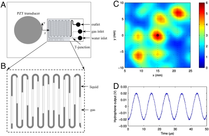
Both challenges can be addressed with our microfluidic design presented in Fig. 1A. The acoustic driving is based on a standing wave generated on the surface of a glass plate with an attached piezoelectric transducer. Gas–liquid interfaces are created using a T junction where gas is injected at constant pressure into the liquid flow (Fig. 1B). The acoustic pressure distribution at approximately 50 μm above the glass plate (at low driving amplitude of 50 V) is presented in Fig. 1C. The pressure reaching up to 6 bars is measured. A prominent standing wave pattern is visible, and the individual peaks oscillate with a nearly sinusoidal shape at the driving frequency of 103.6 kHz (Fig. 1D and Fig. S1). At higher driving amplitude, nonlinear standing capillary waves are excited at the gas–liquid interfaces, i.e., Faraday waves at half the driving frequency. These waves entrap small bubbles that then serve as cavitation nuclei.
Fig. 1.
Microfluidic device design for the creation of sonochemistry and sonoluminescence. (A) Sketch: the piezoelectric transducer for the ultrasound excitation is glued to a glass substrate to which the meandering microfluidic channel is bonded. The inlets consist of two ports for gas and water, respectively, which are connected through a T junction to form large gas–liquid interfaces within the channel. (B) Typical distribution of gas and liquids along the microchannel. (C) Map of the acoustic pressure amplitude (in bars) of the shaded area in A. (D) The time-varying pressure at the indicated position in C (x = 15 mm, y = 0 mm). The rather low excitation voltage of 50 V at the resonance frequency of the system of 103.6 kHz leads to the sinusoidal-varying pressure.
First we present light emission generated through chemical reactions caused by the bubble oscillations (chemiluminescence) and then present sonoluminescence, i.e., the light emitted directly from the collapse of the cavitation bubbles.
Results and Discussion
Visualization of Chemiluminescence.
Because cavitation initiates at the gas–liquid interfaces, it is expected that sonochemical reactions will be most prominent near these locations. We used the well-known oxidation of luminol in a sodium carbonate base solution to monitor the cavitation-induced production of H and OH radicals (12, 13). They subsequently trigger the formation of an amino phthalate derivative with electrons in an excited state. As the excited states relax to lower energy states, excess energy is emitted as visible bluish light. This light emission is captured with an intensified and cooled CCD camera.
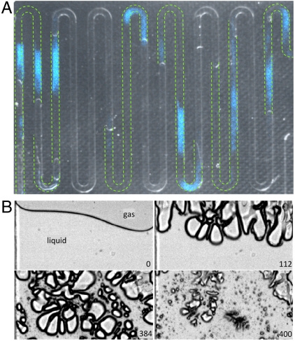
A typical light distribution pattern is shown in Fig. 2A; it is overlaid onto a frame taken with side illumination to resolve the gas–liquid interfaces just before the start of the ultrasound (in gray colors). The green dashed lines in Fig. 2A represent the position of the liquid bodies in the microchannels. Fig. 2A reveals that the luminol emission is occurring only within the liquid phase and always close to the gas–liquid interfaces, precisely at the location where cavitation bubbles are nucleated and driven into large oscillations. Snapshots of bubble oscillations at various stages of the ultrasound driving close to the gas–liquid interface are depicted in Fig. 2B. The bubbles are largely pancake shaped (third frame of Fig. 2B) during maximum expansion, whereas severe deformations occur during collapse (last frame of Fig 2B).
Fig. 2.
Luminol chemiluminescence from cavitation bubbles. (A) Composed picture of the channel geometry (gray background) showing the distribution of liquid and gas phases. The green dashed lines indicate the positions of liquid slugs just before the ultrasound is switched on. The bluish patches are taken with an intensified EMCCD camera and capture the chemiluminescence from the oxidation of luminol. (B) Sequence of images taken with a high-speed recording of the bubble distribution near a gas–liquid interface. The number in each frame is the time in microseconds after turning on the ultrasound. They show consecutively the initial gas–liquid interface leading to the severe surface instabilities, large bubble expansions, and finally the collapses. The interface was exposed to a harmonic driving at an amplitude of 230 V at its resonance frequency of 103.6 kHz. The width of each frame (channel) is 500 μm.
Time-Resolved Luminescence.
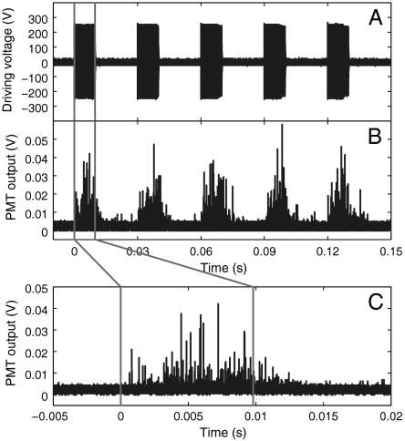
Next we study the time-resolved light emission from pulsed ultrasound excitation with a photomultiplier (PMT) in combination with a high-capacity sampling oscilloscope. The piezoelectric transducer was repeatedly excited at 230-V amplitude for 1,000 cycles every 30 ms with an on/off ratio of 0.49 (Fig. 3A). The inverted signal of the PMT output is plotted in Fig. 3B, and the emission during the first cycle is given enlarged in Fig. 3C. The first light emission is observed several hundred microseconds after the ultrasound is switched on. This can be easily explained by the finite time needed to build up the resonant oscillations; before nucleation and excitation of the cavitation bubbles can occur. This build-up time for maximum cavitation is 380 μs (11) and is similar to the time of the first detected chemiluminescence. There are strong fluctuations in the light emission that seem to increase over the ultrasound exposure. Interestingly, light emission is observed even after the ultrasound is switched off, thus clearly showing the chemical origin of the light emission; only when the OH radicals are chemically depleted, the light emission stops. The observed decay time of 10 ms is several orders of magnitude shorter than the decay times of luminol chemiluminescence in bulk liquid, e.g., 10-s range measured in ref. 14. This speedup is likely due to the small volumes of the microchannel leading to higher advection and diffusion rates (see, for example, ref. 15).
Fig. 3.
Time-resolved chemiluminescence emission. (A) Five bursts of a 1,000-cycle-long sinusoidal signal with an amplitude of 230 V at 103.6 kHz that is repeated every 30 ms and applied to the piezoelectric transducer. (B) The resulting (inverted) voltage signal from the photomultiplier (H5783, Hamamatsu) attached with its circular photocathode (6-mm diameter) to the left part of the microfluidic device. This signal is obtained from the summation of 10 runs with 5 bursts each. (C) An expanded view of the photomultiplier signal from the first burst. The chemiluminescence continues for a short while after the ultrasound has been turned off.
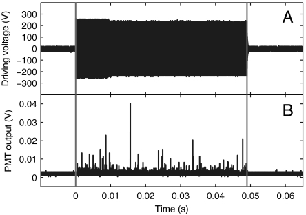
In contrast to chemiluminescence of the previous section, sonoluminescence is caused by the rapid heating of the bubble interior without the use of chemical agent and occurs only during the ultrasonic activation. Fig. 4 reveals pure sonoluminescence in the above-described microfluidic device in air-saturated water and in the absence of luminol. Here, we excited the microfluidic chip 100 times with a 5,000-cycle wave (on/off ratio is 0.01) and integrated the emission events on the oscilloscope. The number of sonoluminescence events detected here is much lower than that of chemiluminescence (Figs. S2 and S3). The low number of events indicates that very few bubble collapses in the constrained microfluidic geometry are sufficiently strong to induce sonoluminescence. Again we find the first light emission to occur only after a start-up time of the ultrasound, which is here 470 μs. In contrast to chemiluminescence (Fig 3C), the light emission stops when the ultrasound is turned off.
Fig. 4.
Sonoluminescence signal. (A) Driving voltage applied to the transducer to generate sonoluminescence consists of 5,000-cycle sinusoidal signals with an amplitude of 230 V at a frequency of 103.6 kHz. (B) The light emission detected with the photomultiplier from 100 repeated signals of A. Note that light disappears when the ultrasound is stopped.
Despite the confined geometry restraints, we have constructed a sonochemical reactor and realized sonoluminescence in a typical microfluidic chip. This geometry may allow correlating bubble dynamics, sonochemical reactions, and sonoluminescence, as well as conducting sonochemistry with very small amounts of liquids. Since the oscillating bubbles are within a well defined region (and not randomly occurring as in bulk fluidic systems), a systematic study on the complex interplay between bubble dynamics, sonochemical reactions, sonoluminescence, and sound waves is now feasible.
Materials and Methods
The microchannel attached on a microscope slide next to a piezoelectric transducer (PZT material, disc transducer, 25-mm diameter with 2.1-mm thickness, Steiner & Martins), as shown in Fig. 1, is made from polydimethylsiloxane. It has two inlets connected through a T junction such that air can be injected into the main (water) channel to create continuous gas–liquid interfaces. The width of the gas inlet and the main channel in the T junction are 50 and 100 μm, respectively. The main channel expands to 500 μm downstream to achieve shorter gas/liquid slugs and thus longer interfaces in the channel. The height of the channel is 20 μm. The liquid is injected into the microchannel by a syringe pump, while we maintain the air pressure by a pressure controller. The length of the air/water slugs is controlled by the liquid flow rate and air pressure.
The acoustic pressure in Fig. 1 C and D and Fig. S1 is measured with a PVDF hydrophone (RP22s, RP Acoustics) positioned at 50 μm above the microscope slide without the microfluidic device. The hydrophone is acoustically coupled to the glass surface using ultrasound gel. The microscope slide is mounted on a 10-mm thick aluminum plate. The acoustic mapping is done using an x-y translation stage and at low driving of 50-V voltage amplitude to prevent the entrapment of bubbles into the coupling liquid and gas bubble oscillations.
To capture the light emission during the ultrasound excitation, we used an electron multiplying CCD camera (EMCCD, iXon+ 897, Andor) connected to a macrozoom lens (MLH-10x, Computar). After creating gas–liquid interfaces in the microchannel through the T junction, the device and the camera were placed in a carefully darkened environment. The PZT transducer was subsequently excited by an amplifier (AG1021, LF Amplifier/Generator, T&C Power Conversion). The input signal of the amplifier is controlled by a function generator (33220A 20-MHz Function/Arbitrary Waveform Generator, Agilent Technologies).
A photomultiplier (H5783, Hamamatsu) in combination with a sampling oscilloscope (WaveRunner 64Xi-A, LeCroy) able to store more than 107 samples was used to record the time-resolved light emission generated by sonoluminescence and sonochemistry. The PZT transducer was repeatedly excited with a certain on/off ratio to avoid overheating. The timing of the ultrasound excitation was controlled by a delay/pulse generator (Model 575 Digital Delay/Pulse Generator, BNC).
To show the light emission from sonochemical reactions, we used luminol in a sodium carbonate base solution. The solution was prepared as follows: 117 mg of luminol (C8H7N3O2) was dissolved in 100 mL of 0.5 M sodium carbonate (Na2CO3) and was subsequently diluted with water to achieve the expected concentration (e.g., 0.001 M luminol + 0.05 M sodium carbonate). The solution is injected into the channels with a syringe pump at room temperature 20 °C. The aqueous solution was saturated with air.
Supplementary Material
Acknowledgments.
This work is supported by the Agency for Science, Technology and Research through Cross Council Office Grant CCOGA02-014-2008 and Joint Council Office Grant 10/03/FG/05/02, and the Ministry of Education through the Tier 2 Grant T208A1238, both in Singapore.
Footnotes
The authors declare no conflict of interest.
This article is a PNAS Direct Submission.
This article contains supporting information online at www.pnas.org/lookup/suppl/doi:10.1073/pnas.1019623108/-/DCSupplemental.
References
- 1.Walton AJ, Reynolds GT. Sonoluminescence. Adv Phys. 1984;33:595–660. [Google Scholar]
- 2.Crum LA. Sonoluminescence. Phys Today. 1994;47:22–29. [Google Scholar]
- 3.Hilgenfeldt S, Grossmann S, Lohse D. A simple explanation of light emission in sonoluminescence. Nature. 1999;398:402–405. [Google Scholar]
- 4.Putterman SJ, Weninger KR. Sonoluminescence: How bubbles turn sound into light. Annu Rev Fluid Mech. 2000;32:445–476. [Google Scholar]
- 5.Brenner MP, Hilgenfeldt S, Lohse D. Single-bubble sonoluminescence. Rev Mod Phys. 2002;74:425–484. doi: 10.1103/PhysRevLett.77.3467. [DOI] [PubMed] [Google Scholar]
- 6.Suslick KS, Flannigan DJ. Inside collapsing bubble: Sonoluminescence and the conditions during cavitation. Annu Rev Phys Chem. 2008;59:659–683. doi: 10.1146/annurev.physchem.59.032607.093739. [DOI] [PubMed] [Google Scholar]
- 7.Flannigan DJ, Suslick KS. Inertially confined plasma in an imploding bubble. Nat Phys. 2010;6:598–601. [Google Scholar]
- 8.Ohl CD, Lindau O, Lauterborn W. Luminescence from spherically and aspherically collapsing laser induced bubbles. Phys Rev Lett. 1998;80:393–397. [Google Scholar]
- 9.Suslick KS. Sonochemistry. Science. 1990;247:1439–1445. doi: 10.1126/science.247.4949.1439. [DOI] [PubMed] [Google Scholar]
- 10.Brotchie A, Grieser F, Ashokkumar M. Effect of power and frequency on bubble-size distributions in acoustic cavitation. Phys Rev Lett. 2009;102:084302. doi: 10.1103/PhysRevLett.102.084302. [DOI] [PubMed] [Google Scholar]
- 11.Tandiono, et al. Creation of cavitation activity in a microfluidic device through acoustically driven capillary waves. Lab Chip. 2010;10:1848–1855. doi: 10.1039/c002363a. [DOI] [PubMed] [Google Scholar]
- 12.Henglein A, Ulrich R, Lilie J. Luminescence and chemical action by pulsed ultrasound. J Am Chem Soc. 1989;111:1974–1979. [Google Scholar]
- 13.Hatanaka S, Mitome H, Yasui K, Hayashi S. Single-bubble sonochemiluminescence in aqueous luminol solutions. J Am Chem Soc. 2002;124:10250–10251. doi: 10.1021/ja0258475. [DOI] [PubMed] [Google Scholar]
- 14.Radi R, Cosgrove TP, Beckman JS, Freeman BA. Peroxynitrite-induced luminol chemiluminescence. Biochem J. 1993;290:51–57. doi: 10.1042/bj2900051. [DOI] [PMC free article] [PubMed] [Google Scholar]
- 15.Rivas DF, Prosperetti A, Zijlstra AG, Lohse D, Gardeniers HJGE. Efficient sonochemistry using microbubbles generated with micromachined surfaces. Angew Chem Int Edit. 2010;49:9699–9701. doi: 10.1002/anie.201005533. [DOI] [PubMed] [Google Scholar]
Associated Data
This section collects any data citations, data availability statements, or supplementary materials included in this article.


