Abstract
We propose a simple method to impose both no-slip boundary conditions at fluid-wall interfaces and at outflow boundaries in fully developed regions for Dissipative Particle Dynamics (DPD) fluid systems. The procedure to enforce the no-slip condition is based on a velocity-dependent shear force, which is a generalized force to represent the presence of the solid-wall particles and to maintain locally thermodynamic consistency. We show that this method can be implemented in both steady and time-dependent fluid systems and compare the DPD results with the continuum limit (Navier-Stokes) results. We also develop a force-adaptive method to impose the outflow boundary conditions for fully developed flow with unspecified outflow velocity profile or pressure value. We study flows over the backward-facing step and in idealized arterial bifurcations using a combination of the two new boundary methods with different flow rates. Finally, we explore the applicability of the outflow method in time-dependent flow systems. The outflow boundary method works well for systems with Womersley number of O(1), i.e., when the pressure and flowrate at the outflow are approximately in-phase.
Keywords: No-slip, shear force, DPD, Navier-Stokes, unsteady flow
1 Introduction
Dissipative Particle Dynamics (DPD) was introduced as an off-lattice algorithm [1,2] and has been used to simulate complex fluid systems [3–8] at the mesoscopic level. As a particle based method, each DPD particle represents a coarse-grained group of molecules and interacts with other particles within a certain cut-off range through three forces. Specifically, besides the spatial conservative force term, each DPD pair interaction also consists of a velocity-dependent dissipative force and a random force term, originated from the coarse-graining procedure [9,10] of a molecular dynamics (MD) system. In contrast to MD, the larger spatial and time scales enable the DPD method to be used successfully in simulations of various soft matter systems, such as the polymer and DNA suspensions [4–6], platelet aggregation [7], and red blood cells in shear flow [11,8] and in blood flow [12].
One of the fundamental problems for these hydrodynamic systems is how to impose proper boundary conditions (BCs) on non-periodic domains, e.g., on the fluid-wall and outflow boundaries. For bulk systems, the Lees-Edwards boundary method [13] and the reverse Poiseuille flow method [14] have been proposed to simulate shear and Poiseuille flows, respectively. These methods employ periodic BCs in order to avoid explicit modeling of solid walls and to eliminate artificial density fluctuations. For non-periodic systems, where solid boundaries play an important role, several attempts have been made to simulate the wall-fluid interface. In general, there exist two main approaches. The first approach is based on the representation of a wall by frozen particles while the fluid-wall interactions are prescribed by the conservative and dissipative forces between the fluid and the wall particles, e.g., simple fluid [15], colloidal suspension [16] and a polymer solution between bounded walls [17]. In the second approach, the fluid-wall interactions are represented by certain effective forces with the combination of proper reflections to prevent particle penetration. In Ref. [18], a continuum-based approximation of the uniformly distributed wall particles is employed and combined with the bounce-back reflection to enforce no-slip BCs. In Refs. [19] and [20] a boundary force is computed adaptively to eliminate density fluctuations and excessive slip velocity near a solid wall, respectively.
However, to the best of our knowledge, little work has been done for the following two boundary problems. The first problem is how to impose noslip BCs for time-dependent fluid flows using proper effective boundary forces rather than the wall particle representation. An oscillatory Stokes flow was simulated in [15] using the wall particle representation with adjusted force parameters. In Ref. [21], Couette flow with a transient start-up was simulated by creating a dynamic wall layer, where images of the DPD particles from the fluid layer next to the wall are inserted into the wall layer with a random shift. Both methods explicitly employ wall particles introducing additional computational cost and complexity. The second problem we would like to address is how to impose the outflow BCs for a fully developed fluid flow. Werder et al. [22] proposed an algorithm based on particle insertion/deletion, which relies on the knowledge of the velocity profile at the outflow. However, as we know from continuum CFD, the outflow profiles are rarely known.
In this paper, we focus on the two problems: (i) the no-slip BCs for unsteady flows, and (ii) the outflow BCs. In Section 2 we briefly describe the DPD method. In Section 3, we derive an effective boundary force from the total dissipative force on a single DPD particle in homogeneous shear flow. We show that the effective force can be implemented as the boundary force in the vicinity of the wall and is sufficient to impose no-slip BCs for unsteady flows while maintaining thermodynamic consistency near the boundary in contrast to an abnormal temperature profile in [23]. We validate the method by comparing the numerical results of transient Couette and oscillatory Stokes and Womersley flows with the corresponding analytical solutions. In Section 4, we propose the outflow boundary method which is similar to the Neumann BCs in CFD for fully developed flows. We validate this method through simulations of the backward facing step and arterial bifurcation flows in combination with the no-slip BCs introduced in Section 3. Furthermore, we test the outflow method for the case of a time-dependent flow system by considering the unsteady Womersley flow. We conclude with a brief summary in Section 5.
2 DPD method
We consider the standard DPD formulation [1] with the motion of each particle governed by
| (1) |
where ri, vi, m are the position, velocity, and mass of the particle i, and , , are the total conservative, dissipative and random forces acting on the particle i, respectively. Under the assumption of pairwise interactions the DPD forces are given by the sum of the pair interactions with the surrounding particles as follows
| (2) |
| (3) |
where rij = ri – rj, rij = ∣rij∣, eij = rij/rij, and vij = vi – vj. rc is the cut-off radius beyond which all interactions vanish. The coefficients a, γ and σ represent the strength of the conservative, dissipative and random force, respectively. The last two coefficients are coupled with the temperature of the system by the fluctuation-dissipation theorem [2] as σ2 = 2γkBT. Here, ξij are independent identically distributed (i.i.d.) Gaussian random variables with zero mean and unit variance. The weight functions wD(r) and wR(r) are defined by
| (4) |
where k = 1.0 in the standard DPD method; however, other values of k have been used to increase the viscosity of the DPD fluid [5,20]. In the current work we chose k = 0.25, a = 25.0, σ = 3.0, γ = 4.5, and kBT = 1.0. The number density of the fluid is n = 3.0.
3 No-slip boundary conditions
3.1 Boundary method
Generally, we need to impose a certain boundary force on the particles near the solid wall to impose the no-slip boundary condition. In Ref. [24], the boundary force is extracted from the fluid-solid interaction for Smoothed Particle Hydrodynamics (SPH). Similarly, we use an effective force to represent the presence of solid-wall next to DPD fluid. Rather than computing the force contribution from the wall directly, let us start with a DPD particle in shear flow. We define the flow direction in Fig. 1, and the shear rate , where u(z) = ⟨vx⟩. We calculate the force on the particle i exerted by the particles in the semi-spherical region satisfying (zj – zi) > h, i.e, the particles in the gray area drawn in Fig. 1. Using the continuum approximation the total conservative force on the particle i can be evaluated as
| (5) |
where g(r) is the radial distribution function of DPD particles, Vs/ Vex(h) represents the spatial part of the fluid domain shown by the gray area in Fig. 1. The x and y components of Fc(h) vanish due to spherical symmetry. We note that the z component fp(h) is exactly the pressure force proposed in [22] to eliminate density fluctuations in the vicinity of the wall boundary.
Fig. 1.
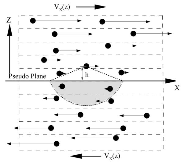
A sketch of the shear flow illustrated by DPD particles. The arrows represent the magnitude and direction of the particles’ average velocities. The solid line represents a reference plane for the target particle while the total interaction of the target particle with the DPD particles below the reference plane (the gray area) is calculated using Eq. (8).
Next, we calculate the total dissipative force on the particle i as follows
| (6) |
This force depends on the instantaneous velocity difference between particle i and j, but we notice that in the bulk shear flow the velocity difference satisfies . Thus, we can calculate the ensemble average of FD(h) as
| (7) |
We further simplify this term by taking the continuum limit of the force as follows
| (8) |
where the y and z components vanish due to spherical symmetry. After the integration over the angles in the spherical coordinates the x-component is simplified as
| (9) |
where γd(h) is a function of the height from the particle i to the reference plane and corresponds to the average velocity difference between the particle i and the reference plane. The function γd(h) is shown in Fig. 2 and a best fit is given by
| (10) |
where C1 = 0.8504, C2 = 9.6 × 10⁻³, C3 = 4.0 × 10⁻⁴ and δh = 0.01.
Fig. 2.
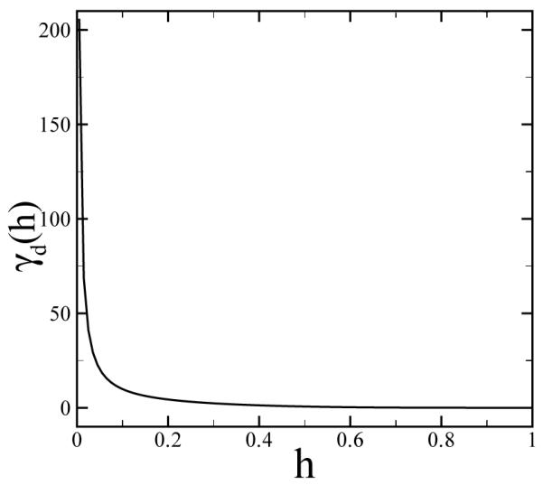
The dissipative force coefficient for a single DPD particle in shear flow with respect to the distance to the reference plane calculated by Eq. (10).
Now we consider fluid flow above the reference plane replaced by a solid wall. Each fluid particle within the distance h < rc from the solid wall is subject to the effective forces which compensate for the interactions with the “missing” particles under the reference plane (solid wall). A natural choice of the effective shear force is the ensemble average of the dissipative force as follows
| (11) |
where vx and U are the velocities of the particle and the wall along the flow direction. The main approximation we rely on is that the velocity profile near the solid boundary remains linear with a quasi-constant shear rate . In addition, for thermodynamic consistency a thermal random force is required to represent the fluctuation part of interactions with the “missing” particles, i.e.,
| (12) |
where ξ is an i.i.d random variable with the Gaussian distribution and σd(h)2 = 2kBTγd(h). We note that the analytical solution of the effective force shown in Eq. (9) and Eq. (11) applies only to the fluid near a planar surface, as these equations are not valid for a fluid system with arbitrary curvilinear boundary geometry. In principle, Eq. (9) should be replaced with integration over the corresponding curvilinear boundary. However, for simplicity, we can still use a “piecewise-plane” approximation even for complex geometries. The main assumption is that the near-wall profile can be approximated linearly. The corresponding force equation is not going to be “exact” for cases with arbitrary geometries, but it can be a very good approximation as shown in our numerical tests.
In summary, under the assumption of the linear velocity profile near the solid wall, no-slip BCs can be enforced through the three effective forces: the pressure force defined in Eq. (5) acting in the normal direction to the wall, and the dissipative and random forces defined in Eqs. (11) and (12) acting along the flow direction. Thus, we define the boundary force fnoslip for the no-slip BCs as follows
| (13) |
where corresponds to the shear direction. Finally, to prevent penetration of the solid wall by fluid particles, specular reflection [22] is imposed for each DPD particle on the fluid-solid interface.
3.2 Numerical verification
The proposed boundary method is verified through simulations of different prototype flows. The first test is the steady plane Couette flow. The DPD fluid is confined between two parallel plates placed at y = 0 and y = 10 with periodic BCs imposed along the other two directions. The velocity of the upper plate is U = 1.0 and that of the lower plate is U = 0.0. The parameters of the DPD fluid are specified in section 2. Fluid particles near the two boundaries are subject to the velocity-dependent force feff (vx – U) described in the previous section. The system is integrated over 5 × 10⁴ time steps with the time step dt = 5×10⁻³. Statistical averaging is performed over the second half of the simulation. Fig. 3 shows the velocity, density and temperature profiles across the flow. The no-slip BCs are satisfied and the velocity profile is in excellent agreement with the analytical solution. Moreover, the density and temperature profiles are uniform across the computational domain showing no density fluctuations and verifying the thermodynamic consistency of the boundary method. The effective boundary forces mimic a system which can be viewed as a part of the unbounded shear flow whose bulk properties are successfully recovered. The boundary method was also tested for the case of steady Poiseuille flow, and the numerical results agree well with the corresponding analytical solution.
Fig. 3.
Left: velocity profile of the plane Couette flow. Right: density and temperature profiles. The triangle symbols represent the numerical results by DPD using Eq. (13). The circle symbols correspond to the numerical results by Eq. (13) without the random force term. The diamond symbols show the numerical results by the adaptive boundary method used in [20]. The solid lines are the analytical solution.
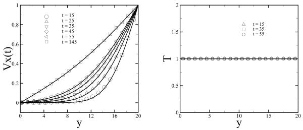
Next, the no-slip BCs are tested for the three unsteady flows: (i) sudden startup of the Couette flow; (ii) Stokes flow over an oscillating plate; (iii) plane Womersley flow. For the first test the DPD fluid is confined between two parallel plates placed at y = 0 and y = 20. The size of the computational domain is 20 × 20 × 40 with periodic BCs along the x and z directions. The viscosity of the DPD fluid is equal to ν = 0.54 measured by the periodic Poiseuille flow method [14]. To improve the statistical averages of the DPD results we run ten independent replicas of the DPD system with different initial conditions. The initial state of each replica is obtained by running them independently for several hundred time steps with the velocity of both the upper and lower plates set to zero. Then, the velocity of the upper plate is set to U = 1.0 at the time t = 0, while the velocity of the lower plane is kept at U = 0.0. The velocity profile of each replica is recorded as a function of time and the final result is obtained by taking the ensemble average of all replicas. Figure 4 shows the simulation results and the corresponding analytical solution for the transient Couette flow at various times. The DPD results agree well with the analytical solution for different times. As time increases the flow converges to the steady case shown in Fig. 3. Note that the fluid velocity near the upper plate (y = 20) is very sensitive to the BCs. Thus, even a small slip at the upper plate would greatly a ect the velocity profiles.
Fig. 4.
Left: velocity profiles of the sudden start-up of Couette flow at different times. The symbols correspond to the simulation results, while the solid lines represent the analytical solution of the Navier-Stokes equation. Right: instantaneous temperature of the system at different times.
The second test case is the oscillatory Stokes flow over a flat plate, where the velocity of the lower plate changes according to the time-dependent function U(t) = sin(Ωt) with Ω = 2π/40. The upper plate has velocity U(t) = 0 and is placed at y = 20 which is far enough from the lower plate to yield a good approximation for the semi-bounded oscillatory Stokes flow. The DPD simulations are run over 80 periods and the statistical average of velocity is accumulated over the last 40 periods at different times. In Fig. 5 the simulation results are compared with the analytical solution [25] given by
| (14) |
where Y = y(ν/Ω)−1/2 is the dimensionless distance, and T = Ωt is the oscillation period. Note that Eq. (14) is derived for a semi-infinite system, however the dimensionless height of the upper plate in simulations is H = 10.87 which is sufficient to recover the analytical solution as illustrated in Fig. 5.
Fig. 5.
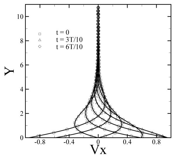
Velocity profiles of the oscillatory Stokes flow at times , where k = 0, 1, 2, …, 7 and T is the oscillation period. The symbols are the numerical results, while the solid lines represent the analytical solution given in Eq. (14).
Finally, we apply the proposed boundary method to a time-dependent pressure-driven flow. The computational domain assumes the same size as the plane Couette flow, where DPD particles are confined between two plates placed at y = 0 and y = 20 with periodic BCs imposed along the x and z directions. The flow is driven by a time-dependent body force on each particle in the x-direction fbody = f0 + f cos(Ωt), which is equivalent to a pressure gradient dP/dx = nfbody, where n is the density of the DPD fluid. The no-slip BCs are imposed on both plates. In the continuum limit, this flow is called the Womersley flow with the analytical solution given by
| (15) |
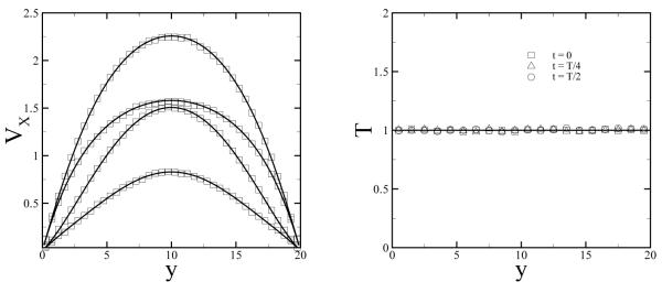
where p0 = f0n, p* = fn are the amplitude of the steady and oscillating pressure gradient respectively; h, α, x1 and x2 are defined by , , x1 = cos α cosh α and x2 = sin α sinh α. For the DPD simulations we choose f0 = 0.0167, f = 0.05 and Ω = 2π/80, and the statistical average is collected over the last 40 periods. Figure 6 shows the velocity and temperature profiles of the Womersley flow at different times. The numerical results are in good agreement with the analytical solution.
Fig. 6.
Left: velocity profiles of the flow driven by an oscillating pressure gradient. The symbols, from the bottom to the top, correspond to the simulation results obtained at , where k equals to 1, 0, 2, 3. The solid lines represent the exact solution for the Womersley flow given in Eq. (15). Right: instantaneous temperature of the DPD system at different times.
4 Outflow boundary conditions
In this section, we consider different flow systems with non-periodic BCs, where inflow and outflow boundary conditions have to be imposed. Rather than imposing the strong Dirichlet BCs with a velocity profile explicitly specified at the outflow boundary [22], we explore the weak condition as in the standard CFD methods, where the BCs are implicitly imposed under the assumption that the flow is fully developed. However, unlike the CFD methods, in DPD it is not straighforward to impose explicitly pressure values at the outflow boundary. Instead, if the pressure value and the flowrate at the outflow are approximately in-phase, we can impose the flowrate at the outflow boundary. Imposing the flowrate at the outflows is in fact common practice in standard CFD. For example, in the so-called “advection-outflow condition”, the advection velocity is computed so that the total mass is conserved. Alternatively, the divergence-free constraint is re-enforced in other outflow formulations, e.g., see [26].
4.1 Boundary method
For a particle fluid system with non-periodic open boundaries the two physical properties need to be controlled are: the flow rate at the inflow/outflow boundaries and the velocity gradient at the outflow similarly to the fully developed condition in CFD. Let us consider the open fluid system shown in Fig. 7. We place a pseudo-plane P perpendicular to the flow direction. From the macroscopic perspective the flow flux through the plane is determined by the velocity profile at the plane P. In practice, this plane can be modeled as an inflow with a specified velocity profile. Inflow at the plane P can be simulated by inserting DPD particles into a near boundary layer according to the local particle flux. Without loss of generality, we consider a local area dA on the plane, and define NA as the number of DPD particles to be inserted into the plane P at the area dA according to the following equation:
| (16a) |
| (16b) |
where i is the timestep of the simulation, n is the number density of the DPD fluid, and vn is the local normal velocity at the inflow plane. When Eq. (16b) is executed (it can be executed several times if ), one DPD particle will be inserted next to the plane P at the local area dA. The velocity of the inserted particle is generated according to the Maxwellian distribution with known temperature of the system and local boundary velocity. In general, the position of the inserted particle at dA has to be generated by the USHER algorithm [27] to minimize the local thermal disturbance due to the inserted DPD particle. However, we omit this procedure in practice since we found that the system remains stable with random insertions due to the soft interactions between DPD particles. The disturbances on the local number density due to insertions is on the order of 5%.
Fig. 7.

A sketch of the domain of an open flow system. The solid lines are the wall boundaries. The plane P represents the inlet through which DPD particles enter the domain with a specified velocity profile. The plane Q represents a pseudo-plane where the flow is fully developed. A and B correspond to two regions adjacent to the plane Q, where the flow is also fully developed.
Next, we consider the region of the fluid system where the flow is fully developed. Let us place another plane Q in this region and consider the two regions A and B adjacent to the plane, as shown in Fig. 7. Physically, there should be no macroscopic difference between A and B since the flow is fully developed in this region, i.e., the macroscopic velocity should be identical in the two regions. In practice, we model this pseudo-plane as the outflow BCs. The DPD particles which pass through this outflow plane are deleted from the system. To control the flow rate at the outflow and eliminate any velocity differences between the two regions (A and B) we apply an adaptive force on the DPD particles near the outflow as follows
| (17a) |
| (17b) |
| (17c) |
where the first term of the adaptive force eliminates the velocity difference between the two regions and the second term imposes proper flow rate at the outflow boundary. The parameters k, ξ, and βk are the iteration number, the relaxation parameter, and the adaptive coefficient, respectively. Also h is the distance from a particle to the outflow plane, and r0 defines the total width of regions A and B together. In this work, r0 is chosen to be the cutoff radius of the DPD particle interactions if not specified otherwise; p defines the stiffness of the adaptive force and p is equal to 6. We choose this value by considering a static single DPD particle in uniform flow with the average velocity of . We compute the dissipative force fnorm(h) on the target particle from the particles located in a semi-spherical region behind the pseudo-plane. The dissipative force scales as fnorm ~ fnu, where fn is best fitted by (1.0 – h/rc)6. Moreover, and in equation above are the average normal velocities in the regions A and B during the time between the (k – 1)th and kth iterations. Also, q is the total number of the under-relaxation steps, which is coupled to the number density of the system as follows
| (18) |
where nk is the average number density during the kth iteration, and δn is the accepted deviation of the system’s number density.
The second adaptive force term in Eq. (17a) controls the flow rate at the outflow, where ϕk represents the instantaneous flux at the outflow and ϕ0 corresponds to the desired flux value; fpress(h) is the pressure force defined in Eq. (5). We note that for fluid systems with a single outflow boundary, this term can be neglected. However, for flows with multiple outflows (e.g., arterial bifurcations), this term is necessary to impose the desired flux value at each outflow boundary. In addition to fout the pressure force defined in Eq. (5) is applied on fluid particles near the inflow and outflow planes, which compensates for the “missing” fluid part outside the computational domain.
We note that our method of inserting particles is different from that in [22], where each particle that left the system is re-inserted at the inflow boundary, and hence the number density of the system is strictly conserved. In this work DPD particles are inserted at the inflow plane with no dependence on the number of particles removed. For the insertion method of [22] we found that the desired flux prescribed by the velocity profile at the inflow depends strongly on the number of particles leaving the system, and therefore the numerical system may be unstable. In the current method the instantaneous number density is not strictly conserved, however the converged density remains within the pre-specified tolerance (δn = 0.002n) as shown in the next section.
4.2 Simulation results
The first test of the described method is the plane Poiseuille flow in combination with the no-slip method proposed in section 3.1. The computational domain is similar to that shown in Fig. 7 with periodic BCs in the z direction. The fluid is confined between two walls placed at y = 0 and y = 10 and the inflow and outflow planes are placed at x = 0 and x = 20, respectively. DPD particles are inserted at the inflow according to the parabolic velocity profile given by
| (19) |
where v0 = 1.0 and H = 10. To impose the no-slip BCs at the walls particles near the walls are subject to the no-slip force defined in Eq. (13). In addition, particles near the outflow plane (x = 20) are subjected to the adaptive outflow boundary force. Specifically, the outflow region was divided into 20 bins across the flow in the y-direction and each bin was further divided into two sub-volumes, labeled as A and B. The velocity in each sub-volume vA and vB, as well as the number density of the system, are sampled during the time between two consecutive iterations. The flow converges within approximately 100 iterations, where one iteration corresponds to 100 time steps. Statistical averaging is performed during 1×10⁴ time steps after steady state is achieved.
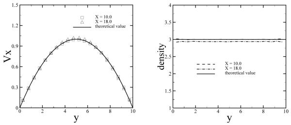
Physically, this system represents a part of the fully developed Poiseuille flow given by Eq. 19. Therefore, a parabolic velocity profile is expected in the downstream region as in upstream. Fig. 8 shows velocity and density profiles obtained at the planes in the middle of the system at x = 10.0 and in the outflow region at x = 18.0. The simulation results agree well with the prescribed inflow profile. The fluid density at the outflow (x = 18.0) is slightly lower (ρ = 2.94) than the exact number density due to a finite compressibility of the DPD fluid.
Fig. 8.
Velocity profiles (left) and density profiles (right) of the fully developed Poiseuille flow. The DPD results are shown for the planes x = 10.0 and x = 18.0. The solid lines correspond to the analytical solution.
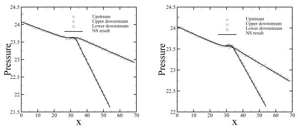
For a more quantitative analysis, we compute the pressure profile along the flow direction shown in Fig. 9. The DPD results agree well with the analytical prediction given by
| (20) |
where H = 10, μ = 1.62, and vmax = 1.0. The small fluctuation at the inlet/outlet boundary is mainly due to the particle insertion and the super-position of the boundary force.
Fig. 9.
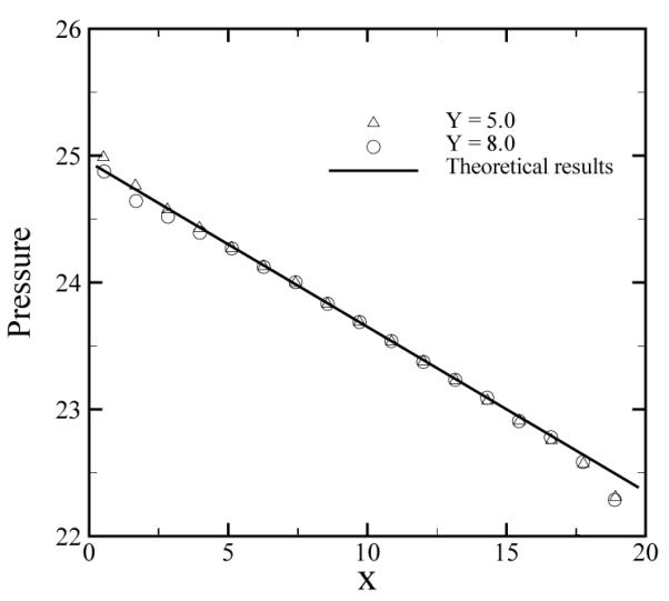
Pressure profile for the Poiseuille flow along the x direction. The symbols represent the numerical results by DPD extracted at y = 5 and y = 8, and the solid line represents the analytical solution.
The compressibility of the DPD fluid can be approximated [3] as follows
| (21) |
where α = 0.101 and therefore dP/dρ = 16. The density difference between x = 10 and x = 18 predicted by Eq. (21) is approximately Δρ = dρ/dPΔP = 0.065, which agrees well with the simulation results. Moreover, the adaptive force fout applied at the outflow serves as a perturbation term on the pressure force fp defined in Eq. (5), which also contributes to the density fluctuations. Therefore, the proposed boundary method is valid for nearly incompressible fluid flows since the boundary forces are based on the global number density of a simulated system. Large density fluctuations due to finite compressibility are likely to void the method’s applicability.
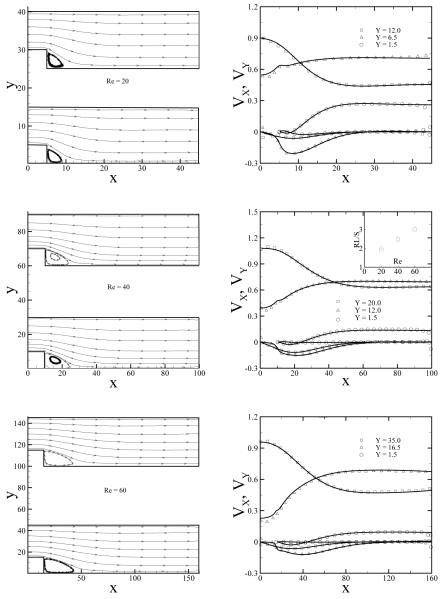
For the second test we consider the backward-facing step flow at different values of Reynolds number (Re). The computational domain is illustrated in Fig. 10 where Re is defined as vmaxH/ν. A parabolic velocity profile defined by Eq. (19) is imposed at the inflow with vmax = 1.08 and the height of the inlet channel is H = 10, while the step height is chosen to be . For different Re numbers the height of the inlet and the size of step is scaled accordingly while vmax is fixed. The no-slip boundary condition is imposed by the dissipative force for all the DPD particles near the solid wall defined by Eq. (10). We compare DPD results with Navier-Stokes results obtained by the spectral element simulation solver NEKTAR [28].
Fig. 10.
Streamlines (left) and velocity profiles (right) for backward facing step flow at Re = 20, 40 and 60. The velocity profiles are extracted at different planes as labeled in the plots. The symbols correspond to the DPD results and the solid lines represent the numerical solution of NS equation. The inset plot in the velocity plot of Re = 40 shows normalized recirculation lengths of the step flow as a function of Re number. The square symbols correspond to the DPD results and the triangle symbols are the NS results.
Fig. 10 presents the simulation results obtained with DPD and with the spectral element method for Re = 20, 40 and 60. The streamlines agree well for the two methods. In addition, we extract several velocity and pressure profiles at different heights for a more detailed comparison with the NS solution shown in Figs. 10 and 11. The DPD results are in good agreement with the NS solution with slight deviations near the inlet and outflow boundaries within the distance of 4rc. This appears to be due to the density fluctuations near those boundaries. At the inlet the number density is approximately 5% larger than the global density due to particle insertions. At the outflow region additional density fluctuations are introduced due to the adaptive force serving as a perturbation term to the pressure force term. We note that the velocity deviations at the outflow will not propagate upstream due to a finite speed of sound [29] in the DPD system. Therefore, the outflow region can be treated as a “buffer layer” region with perturbed number density, where the results may not be accurate. Moreover, we note that the shear rate varies (even changes sign) along the lower wall, which defines the recirculation length. In the inset plot of Fig. 10 we show the recirculation length of the step flow normalized by the step height S as a function of the Reynolds number. The values of the normalized recirculation lengths scale linearly with Re number showing good agreement with the spectral element method results. This further verifies that no-slip BCs are well imposed locally for different shear rates.
Fig. 11.
Pressure profiles for the step flow for Reynolds numbers Re = 20, 40, 60. The symbols represent DPD simulations, while the solid lines correspond to the NS results.
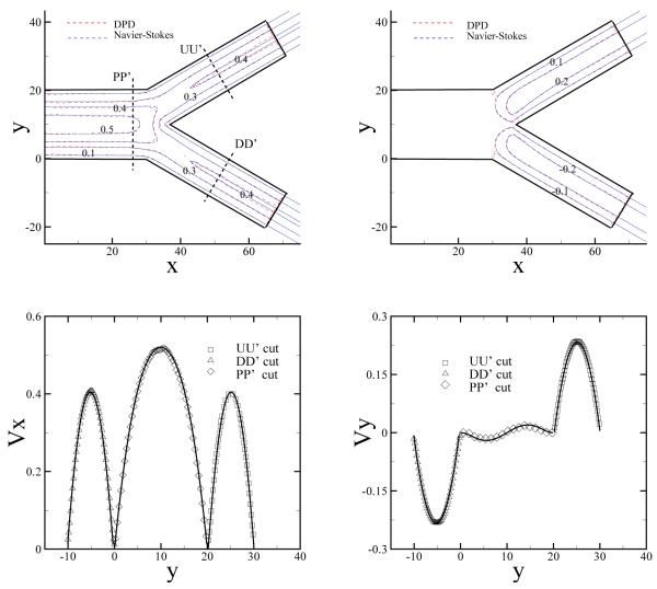
Next, we consider several flow systems with multiple outflow boundaries such as those encountered in the human arterial tree. Fig. 12 shows a bifurcated channel flow with two symmetric outflow boundaries. The channel is divided into two branches at L = 30 with the branch angle θ = π/3. The parabolic velocity profile defined in Eq. (19) is imposed at the inlet with v0 = 0.72 and H = 20 and periodic BCs are imposed along the z direction. The outflow BCs are imposed separately at the two outflow boundaries with the adaptive force updated according to Eq. (17a). Fig. 12 shows velocity contours in both x and y directions. For comparison we also plot the numerical results of the NS equation with identical pressure values imposed at the two outflow boundaries The DPD results show good agreement with the continuum results apart from the regions near the outflow boundaries and near the bifurcation point due to the density fluctuations. The fluctuations near the outflow are due to the adaptive force as discussed previously. The fluctuations near the bifurcation point are mainly due to finite compressibility of the DPD fluid.
Fig. 12.
(Color) Top: 2D contour plot of velocity for both x (left) and y (right) directions for a symmetrically bifurcated channel flow obtained by DPD and NS equation. Bottom: 1D plot of the velocity profile at PP’, DD’, and UU’ cuts. The symbols are the DPD results and the solid lines represent the NS results.
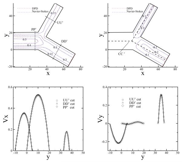
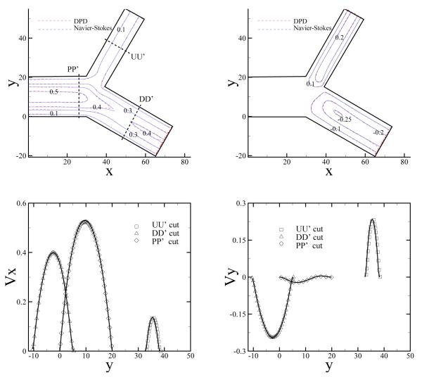
Furthermore, we consider a bifurcated system with prescribed flow rate at each boundary as shown in Fig. 13. The planar channel is divided into two non-symmetric channels at L = 30 with the bifurcation angle θ = π/2. The widths of the two sub-channels scale as . A parabolic velocity profile defined in Eq. (19) is imposed at the inlet with v0 = 0.54 and H = 20. This flow system resembles a small part of the arterial network, where additional information downstream may be unknown. To this end, we can prescribe the ratio of flow rates between the two outlets. The specified flow rate at each of the outlet is imposed through the force defined in Eq. (17a). The different ratio value corresponds to the different pressure values imposed on the outlets. On the other hand, the total flow rate of the two outlets is equal to the inflow rate to ensure mass conversation of the system. We consider two cases where the flow rates at the two outflow boundaries are 1:2 and 1:3, respectively. For the reference Navier-Stokes results, we use the method described in Ref. [30]. In both cases, the DPD results are in good agreement with the corresponding Navier-Stokes results as shown in Figs. 13 and 14.
Fig. 13.
(Color) Top: 2D contour plot of velocity for both x (left) and y (right) directions for a non-symmetrically bifurcated channel flow obtained by DPD and NS equation. The flow rates of the two outflow boundaries scale as 1 : 2. Bottom: 1D plot of the velocity profile at PP’, DD’, and UU’ cuts. The symbols are the DPD results and the solid lines represent the NS results.
Fig. 14.
(Color) Top: 2D contour plot of velocity for both x (left) and y (right) directions for an non-symmetrically bifurcated channel flow obtained by DPD and NS equation. The flow rates of the two outflow boundaries scale as 1 : 3. Bottom: 1D plot of the velocity profile at PP’, DD’, and UU’ cuts. The symbols are the DPD results and the solid lines represent the NS results.
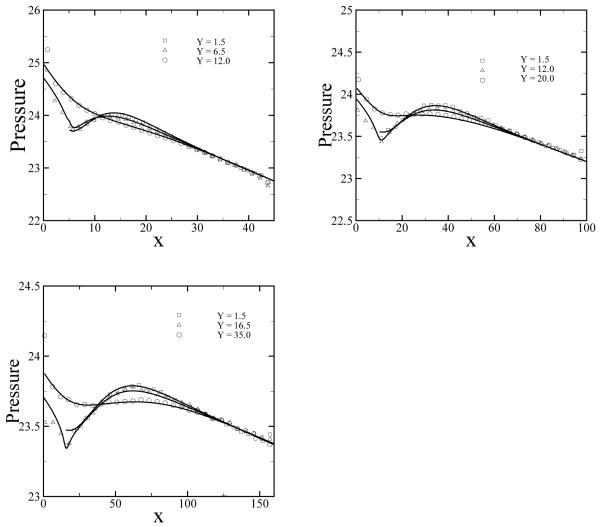
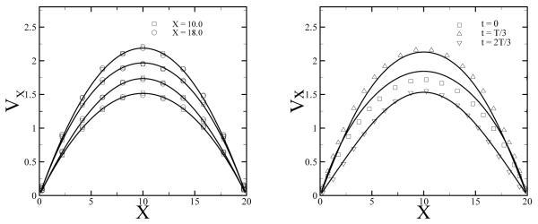
The different flow rates controlled by our method correspond to different pressure values at the outflow boundaries. Therefore, we also look at the pressure distribution for different flow ratios. Fig. 15 presents the pressure distributions along the centerline of the channel marked as CC’ in Fig. 13. The pressure difference between the two outflow boundaries is larger for the flow ratio of 1:2, since a larger flow rate for the upper branch corresponds to a larger pressure drop along the branch. For both cases the DPD results agree well with the NS solutions. The flow examples used in this study show that the outflow boundary method usually converges within a few thousand time steps. Therefore, we can extend this method to unsteady flows with a time-dependent inflow velocity profile. For a test we consider the pulsatile flow, where the fluid is confined between the plates at y = 0 and y = 20, and the inflow and outflow planes are placed at x = 0 and x = 20, respectively. The inflow velocity profile is given by Eq. (15) with f0 = 0.06, f = 0.03 and Ω = 2π/200. The corresponding Womersley number α is equal to 1.71, which is a typical value for biological flow systems [31]. The DPD particles are inserted next to the inflow plane using the instantaneous inflow velocity profile and the boundary force is updated according to Eq. (17a). Statistical average is taken over the last four periods. Fig. 16 (left) shows velocity profiles extracted at x = 10 and x = 18 at different times. The DPD results are in good agreement with the theoretical predictions. However, for flows with a higher Womersley number, the current method may not be sufficient to track instantaneous velocity profile. As shown in Fig. 16 (right) for the higher frequency Ω = 2π/50 (α = 3.42), the DPD results begin to deviate from the theoretical predictions. This appears to be due to a finite compressibility of the DPD fluid. Thus, the boundary information is not able to propagate through the computational domain with such high frequency.
Fig. 15.
Pressure distribution along the centerline CC’ of the channel shown in Fig. 13. The flow rate ratio at the outflow boundaries scales as 1 : 2 (left) and 1 : 3 (right). The solid line corresponds to the NS results.
Fig. 16.
The velocity profiles extracted from the Womersley flow with Ω = 2π/200 (left) and Ω = 2π/50 (right). Left: the solid lines, from top to bottom, represent the theoretical predictions at t = T/4, 0, 2T/4 and 3T/4. The square and circle symbols represent the numerical results extracted at x = 10 and x = 18. Right: the solid lines, from top to bottom, represent the theoretical predictions at t = T/3, 0, 2T/3, the symbols represent the DPD results extracted at x = 10.
5 Summary and Discussion
In this work two important issues on boundary conditions for particle simulations of fluid systems have been addressed: the no-slip BCs at a wall-fluid interface and the outflow BCs for non-periodic flow systems. We introduced two boundary methods validated for various flow problems. Starting from a single DPD particle in shear flow we computed the total dissipative interaction of this particle with surrounding particles. The dissipative interaction is computed as a function of the distance from the target particle to the pseudo-plane placed at different positions. For wall bounded systems, no-slip BCs are modeled by imposing the effective boundary forces (Eq. (13)) on DPD particles near the walls. Originated from the bulk shear flow, this boundary method can effectively impose no-slip BCs without artificial density and thermal fluctuations near the walls. The tested unsteady flows of the sudden start-up Couette, oscillatory Stokes and Womersley flows further validate the proposed no-slip boundary method. The backward-facing step flow verifies that the method works well locally for different shear rates. Moreover, this method is free of boundary particles, and therefore it is more e cient in comparison with the method in [21].
We developed the outflow boundary method by considering a fully developed flow region of the bulk system. The BCs are weakly imposed under the assumption of the translational invariance of the velocity profile along the flow direction. In a non-periodic system the outflow boundary is modeled by the boundary force, which consists of two adaptive terms that control the flow rate at the boundary and eliminate the velocity difference in the region adjacent to the outflow boundary. Combined with the no-slip boundary method for fluid-wall interactions, the outflow boundary method is verified for the backward-facing step flow at different Reynolds numbers and for the bifurcated flow with different flow rates, which correspond to different pressure values at the outlets. The simulation results show good agreement with the corresponding analytical or reference solutions apart from the narrow regions near the outflow boundaries, where the velocity fluctuations of maximum 10% are observed due to the perturbation of the boundary force in that region. For quasi-steady flows where the pressure value and flow rate on the outlet boundary are approximately in-phase, the prescribed flow rate corresponds to specified pressure value on the outlet. This is obvious for a fluid system with a single outlet since the flow rate at the outlet equals to the inflow rate for mass conservation. However, for a fluid system with multiple outlets, the different flow ratio prescribed on the outlets corresponds to the different pressure values imposed on the outlets since the information farther downstream is unknown. Moreover, we test the current method for a time-dependent non-periodic flow system. The simulation results agree well with the analytical solution for the flow with Womersley number on the order O(1), which is in the range of typical biological arterial flows [31]. The numerical results begin to deviate from the analytical solution for higher Womersley number due to finite compressibility (sound speed) as well as the out-of-phase condition between the pressure value and the outflow rate.
As a conclusion, this work provides a general framework to impose different BCs. Even though we test the method for Newtonian fluids, our future goal is to apply such BCs to complex fluid systems such as polymer solutions or blood flow, where more sophisticated methods for inserting molecules or cells have to be developed and both slip and no-slip BCs may exist. Some related work has already been done in [32,33]. It would be interesting to further explore how to impose proper BCs for these systems such that the dynamic flow and rheological properties can be correctly predicted.
Acknowledgements
This work was supported by the NSF grant CBET-0852948 and by the NIH grant R01HL094270.
Footnotes
Publisher's Disclaimer: This is a PDF file of an unedited manuscript that has been accepted for publication. As a service to our customers we are providing this early version of the manuscript. The manuscript will undergo copyediting, typesetting, and review of the resulting proof before it is published in its final citable form. Please note that during the production process errors may be discovered which could affect the content, and all legal disclaimers that apply to the journal pertain.
References
- [1].Hoogerbrugge PJ, Koelman J. Simulating microscopic hydrodynamic phenomena with dissipative particle dynamics. Europhys. Lett. 1992;19(3):155–160. [Google Scholar]
- [2].Espanol P, Warren P. Statistical-mechanics of dissipative particle dynamics. Europhys. Lett. 1995;30(4):191–196. [Google Scholar]
- [3].Groot RD, Warren PB. Dissipative particle dynamics: Bridging the gap between atomistic and mesoscopic simulation. J. Chem. Phys. 1997;107(11):4423–4435. [Google Scholar]
- [4].Spenley NA. Scaling laws for polymers in dissipative particle dynamics. Europhys. Lett. 2000;49(4):534. [Google Scholar]
- [5].Fan X, Phan-Thien N, Chen S, Wu X, Ng TY. Simulating flow of DNA suspension using dissipative particle dynamics. Phys. Fluids. 2006;18(6):063102. [Google Scholar]
- [6].Symeonidis V, Karniadakis GE, Caswell B. Dissipative particle dynamics simulations of polymer chains: Scaling laws and shearing response compared to DNA experiments. Phys. Rev. Lett. 2005;95(7):076001. doi: 10.1103/PhysRevLett.95.076001. [DOI] [PubMed] [Google Scholar]
- [7].Pivkin IV, Richardson PD, Karniadakis GE. Effect of red blood cells on platelet aggregation. Engin. Med. Biol. Magazine, IEEE. 2009;28(2):32–37. doi: 10.1109/MEMB.2009.931788. [DOI] [PubMed] [Google Scholar]
- [8].Fedosov D, Caswell B, Karniadakis GE. A multiscale red blood cell model with accurate mechanics, rheology, and dynamics. Biophys. J. 2010;98(11):2295. doi: 10.1016/j.bpj.2010.02.002. [DOI] [PMC free article] [PubMed] [Google Scholar]
- [9].Kinjo T, Hyodo SA. Equation of motion for coarse-grained simulation based on microscopic description. Phys. Rev. E. 2007;75(5):051109. doi: 10.1103/PhysRevE.75.051109. [DOI] [PubMed] [Google Scholar]
- [10].Lei H, Caswell B, Karniadakis GE. Direct construction of mesoscopic models from microscopic simulations. Phys. Rev. E. 2010;81(2):026704. doi: 10.1103/PhysRevE.81.026704. [DOI] [PMC free article] [PubMed] [Google Scholar]
- [11].Pivkin IV, Karniadakis GE. Accurate coarse-grained modeling of red blood cells. Phys. Rev. Lett. 2008;101(11):118105. doi: 10.1103/PhysRevLett.101.118105. [DOI] [PubMed] [Google Scholar]
- [12].Fedosov DA. PhD thesis. Brown University; USA: 2010. Multiscale modeling of blood flow and soft matter. [Google Scholar]
- [13].Lees AW, Edwards SF. The computer study of transport processes under extreme conditions. J. Phys. C: Solid State Phys. 1972;5(15):1921. [Google Scholar]
- [14].Backer JA, Lowe CP, Hoefsloot HCJ, Iedema PD. Poiseuille flow to measure the viscosity of particle model fluids. J. Chem. Phys. 2005;122(15):6. doi: 10.1063/1.1883163. [DOI] [PubMed] [Google Scholar]
- [15].Pivkin IV, Karniadakis GE. A new method to impose no-slip boundary conditions in dissipative particle dynamics. J. Comp. Phys. 2005;207(1):114–128. [Google Scholar]
- [16].Boek ES, Coveney PV, Lekkerkerker HNW, van der Schoot P. Simulating the rheology of dense colloidal suspensions using dissipative particle dynamics. Phys. Rev. E. 1997;55(3):3124–3133. [Google Scholar]
- [17].Fedosov D, Caswell B, Karniadakis GE. Dissipative particle dynamics simulation of depletion layer and polymer migration in micro- and nanochannels for dilute polymer solutions. J. Chem. Phys. 2008;128(14):144903. doi: 10.1063/1.2897761. [DOI] [PubMed] [Google Scholar]
- [18].Revenga M, Zuniga I, Espanol P. Boundary model in DPD. J. Mod. Phys. C. 1998;9(1):1319. [Google Scholar]
- [19].Pivkin IV, Karniadakis GE. Controlling density fluctuations in wall-bounded dissipative particle dynamics systems. Phys. Rev. Lett. 2006;96(20):206001. doi: 10.1103/PhysRevLett.96.206001. [DOI] [PubMed] [Google Scholar]
- [20].Fedosov DA, Karniadakis GE. Triple-decker: Interfacing atomistic-mesoscopic-continuum flow regimes. J. Comp. Phys. 2009;228(4):1157–1171. [Google Scholar]
- [21].Willemsen S, Hoefsloot H, Iedema P. No-slip boundary conditions in dissipative particle dynamics. J. Mod. Phys. C. 2000;11(5):881. [Google Scholar]
- [22].Werder T, Walther JH, Koumoutsakos P. Hybrid atomistic-continuum method for the simulation of dense fluid flows. J. Comp. Phys. 2005;205(1):373–390. [Google Scholar]
- [23].Revenga M, Zuniga I, Espanol P. Boundary conditions in dissipative particle dynamics. Comp. Phys. Comm. 1999;121-122(1):309–311. [Google Scholar]
- [24].Hidenori T, Shoken MM, Minoru S. Numerical simulation of viscous flow by smoothed particle hydrodynamics. Prog. Theor. Phys. 1994;95:939–960. [Google Scholar]
- [25].Panton R. Incompressible Flow. John Wiley & Sons, Inc.; New York: 1996. [Google Scholar]
- [26].Olshanskii MA, Staroverov VM. On simulation of outflow boundary conditions in finite difference calculations for incompressible fluid. Int. J. Num. Meth. Fluids. 2000;33:499–534. [Google Scholar]
- [27].Delgado-Buscalioni R, Coveney P. USHER: an algorithm for particle insertion in dense fluid. J. Chem. Phys. 2003;119(2):978987. [Google Scholar]
- [28].Karniadakis GE, Sherwin SJ. Spectral/hp element methods for CFD. Oxford University Press; Oxford: 2005. [Google Scholar]
- [29].Español P. Hydrodynamics from dissipative particle dynamics. Phys. Rev. E. 1995;52(2):1734–1742. doi: 10.1103/physreve.52.1734. [DOI] [PubMed] [Google Scholar]
- [30].Grinberg L, Karniadakis GE. Outflow boundary conditions for arterial networks with multiple outlets. Ann. Biomed. Engin. 2008;36:1496–1514. doi: 10.1007/s10439-008-9527-7. [DOI] [PubMed] [Google Scholar]
- [31].Loudon C, Tordesillas A. The use of the dimensionless womersley number to characterize the unsteady nature of internal flow. J. Theor. Biol. 1998;191(1):63–78. doi: 10.1006/jtbi.1997.0564. [DOI] [PubMed] [Google Scholar]
- [32].Barber J, Alberding J, Restrepo J, Secomb T. Simulated two-dimensional red blood cell motion, deformation, and partitioning in microvessel bifurcations. Ann. Biomed. Engin. 2008;36:1690–1698. doi: 10.1007/s10439-008-9546-4. [DOI] [PMC free article] [PubMed] [Google Scholar]
- [33].Smiatek J, Allen M, Schid F. Tunable-slip boundaries for coarse-grained simulations of fluid flow. Europ. Phys. J. E: Soft Matter Biol. Phys. 2008;26(1):115. doi: 10.1140/epje/i2007-10311-4. [DOI] [PubMed] [Google Scholar]


