

Abstract
Maintaining adequate fixation between cement and bone is important for successful long term survival of cemented total joint replacements. Mixed-mode loading conditions (combination of tension/compression and shear) are present during in vivo loading, but the micromotion response of the interface to these conditions is not fully understood.
Non-destructive, multi-axial loading experiments were conducted on laboratory prepared (n=6) and post mortem (n=6) human cement-bone interfaces. Specimens were mounted in custom loading discs and loaded at 0, 30, 60, and 90° relative to the interface plane where 0° represents normal loading to the interface, and 90° represents shear loading along the longitudinal axis of the femur. Axial compliance did not depend on loading angle for laboratory prepared (p=0.96) or postmortem specimens (p=0.62). The cement-bone interface was more compliant under tensile than compressive loading at the 0° loading angle only (p=0.024). The coupled transverse to axial compliance ratio, which is a measure of the coupled motion, was small for laboratory prepared (0.115±0.115) and postmortem specimens (0.142±0.101). There was a moderately strong inverse relationship between interface compliance and contact index (r2 = 0.65).
From a computational modeling perspective, the results of the current study support the concept that the cement-bone interface could be numerically implemented as a compliant layer with the same initial stiffness in tension and shear directions. The magnitude of the compliance could be modified to simulate immediate post-operative conditions (using laboratory prepared data set) or long-term remodeling (using postmortem data set).
Introduction
There is continued interest in understanding the role of the cement-bone interface in the loosening process of total joint replacements. Recent work has focused on improved characterization of the mechanics of the interface including mixed-mode loading experiments (Tong et al., 2007; Wang et al., 2010), modification of the interface to improve fatigue strength (Arola et al., 2006), evaluation of postmortem specimens in terms of morphology (Bishop et al., 2009) and micromechanics (Miller et al., 2010), and development of micromechanical (Waanders et al., 2010) and cohesive failure models (Moreo et al., 2006; Perez et al., 2009).
Experimentally, the issue of mixed-mode loading of specimens remains a challenging one because a specimen can only be loaded in one direction to failure, and the failure response in other directions can obviously not be determined with the same specimen. One solution is to perform computational finite element analysis (FEA) of the test specimens, where it is possible to repeat loading and simulate subsequent failure on each model in all manner of loading directions (Waanders et al., 2010). However, there are several assumptions made with these models with regards to the elastic properties and material failure models used for the model constituents and the ability to accurately model the interface morphology between the cement and bone. These factors add a degree of uncertainty to the simulation results. Ideally, experiments that could be performed non-destructively, under a variety of mixed-mode loading conditions could provide new information regarding the micromechanics of the cement-bone interface. Data of this type is currently unavailable in the literature.
Recent experimental work on the cement-bone interface has found that the interface is quite compliant (~10 microns/MPa) (Mann et al., 2008) with sliding and opening occurring from shear and tensile loading conditions, respectively. In addition, this interface becomes more compliant following in vivo service (~50 microns/MPa) (Miller et al., 2010). The question remains as to whether this micromotion is dependent on the loading direction. To address this question we performed multi-loading angle experiments on cement-bone interface specimens. We asked three research questions: (1) does interface compliance depend on loading angle?; (2) are there appreciable coupled transverse motions?; and (3) can interface compliance be explained by contact between cement and bone and source of bone (lab prepared or postmortem retrieval)?
METHODS
Twelve cement-bone interface specimens were created from human cemented femoral hip replacements obtained as postmortem retrievals (n=6) and from laboratory prepared constructs (n=6). A total of eight fresh-frozen proximal femurs were obtained from the SUNY Upstate Medical University Anatomical Gift Program. Four donor bones had cemented femoral components in place (the retrieval group). An additional four donor femora without implants were prepared for cementing by broaching, brush lavage, and distal plugging followed by retrograde introduction of surgical PMMA cement with pressurization and introduction of a double-tapered acrylic stem (the laboratory prepared group). For the laboratory prepared group, bones were warmed to 37 °C in a saline calcium buffered water bath prior to cementing. Specimen data, including donor age, sex, time in service (where appropriate), and anatomic location are shown in Table 1. Specimens were obtained from both postmortem retrievals and laboratory prepared constructs to provide a sample population that spanned a wide range of interface morphologies and interface strengths. Specimen preparation followed a methodology described previously (Mann et al., 2008). Briefly, transverse sections at 10mm intervals of the cemented construct were created. An acrylic side plate was attached between the cement and bone to protect the interface from untoward loading during subsequent handling. Rectangular prism-shaped specimens were then cut from the location of the side plate with 4×9mm cross section. Micro-CT scans (Scanco 40, SCANCO Medical AG, Bruttisellen, Switzerland) were obtained for each specimen to document interface morphology at 12 micron resolution. Specimens were screened to include only those with cement-bone interdigitation less than 3.2mm, to insure that they would fit the loading apparatus.
Table 1.
Source of cement-bone specimens for lab prepared (LP) and postmortem retrieval specimens (PM). Distance from the calcar is measured distally with specimens taken from the distal half of the cemented stem construct.
| Specimen | Age | Sex | Years in Service | Distance from Calcar (mm) | Quadrant | Applied Stress (MPa) |
|---|---|---|---|---|---|---|
| LP1 | 80 | Male | NA | 50 | Posterior | 1.58 |
| LP2 | 80 | Male | NA | 50 | Lateral | 1.02 |
| LP3 | 90 | Female | NA | 80 | Posterior | 0.51 |
| LP4 | 76 | Female | NA | 50 | Anterior | 0.45 |
| LP5 | 75 | Male | NA | 100 | Medial | 0.48 |
| LP6 | 80 | Male | NA | 90 | Lateral | 0.85 |
| PM1 | 67 | Female | 14 | 100 | Medial | 0.04 |
| PM2 | 67 | Female | 14 | 100 | Posterior | 0.39 |
| PM3 | 67 | Female | 14 | 110 | Lateral | 0.14 |
| PM4 | 76 | Female | 2 | 170 | Lateral | 0.17 |
| PM5 | 93 | Female | Unknown | 70 | Posterior | 0.17 |
| PM6 | 77 | Female | Unknown | 90 | Lateral | 0.18 |
Specimens were mounted in a “Brazil nut”-type specimen loading disc with provision to load the interface at 0, 30, 60, or 90° relative to the cement-bone interface (Figure 1A). In terms of a cylindrical coordinate system of the cemented femoral component, 0° represents normal loading along the femoral radial axis, and 90° represents shear loading along the longitudinal axis of the femur. Loading discs were custom fabricated for each specimen from a 9.5mm thick polycarbonate sheet using a computer numerically controlled (CNC) mill. Instead of grips typically used to clamp the specimens, epoxy was used to bond the cement and bone to the loading disc. To achieve this, individual specimen shapes were cu t out of the polycarbonate sheet using the CNC mill. A 3mm slot was milled in the loading disc to bisect the disc into two halves. Small temporary ligaments (Figure 1A) were used to maintain integrity of the two halves of the loading disc prior to insertion of the test specimen and to prevent loads from transferring across the cement-bone interface prior to mechanical testing. The epoxy was carefully applied to the cement and bone surfaces in situ, using an 18 gauge needle via small ports drilled through the loading disc. This ensured that epoxy did not contact the interface between cement and bone.
Figure 1.

Experimental apparatus used to apply axial loads to the loading disc in a water bath (A). The digital image correlation (DIC) sampling points were made at three pairs of points immediately adjacent to the cement-bone interface (B). The loading disc system was designed to allow testing at 0, 30, 60, and 90º loading directions (C).
The loading discs were attached to custom grips using conical screws that aligned the specimen at the four different loading angles. Linear sliders were use d above the top test grip to allow free out of plane displacement. Load (displacement) was applied using a screw driven mechanical load frame (Q-test, MTS Systems, Eden Prarie, MN) with an in-line load cell. Just prior to testing, the side plate connecting the cement and bone was severed, along with the temporary ligaments in the loading disc, using a heated surgical blade. Specimens were tested in an acrylic water bath containing a calcium buffered saline solution at 37°C.
To quantify interface motion during testing, a Digital Image Correlation (DIC) technique was used as described previously (Mann et al., 2008). Briefly, a black paint overspray was applied to the specimen surface to provide texture for the DIC process. A CCD camera with telecentric lens (0.0085 mm/pixel resolution) captured images during loading. Interface motion was measured at 3 pairs of points along the cement-bone interface (Figure 1B). The RMS error of the DIC system was 0.000395mm.
Because the measurement of interface micromotion using the DIC technique was performed as a post-processing step, after completion of mechanical loading, an initial loading procedure was performed on each specimen to determine limits that would result in measurable (on the order of 10 microns), but non-destructive loading. It was determined previously that the interface micromotion at failure in the tensile direction was 0.041±0.017 mm (Mann et al., 2008). Hence, to be in the non-destructive range, 10 m icrons of global crosshead displacement was applied in the tensile direction, with the specimens oriented at the 30° loading angle. Note that application of global displacements of 10 microns should result in lower displacements at the interface, due to compliance at locations other than the cement-bone interface. The local interface micromotion was then calculated using DIC and the initial interface compliance was determined (inverse slope of the applied stress versus interface displacement curve). From t his initial compliance estimate, the applied stress needed to displace the interface 8 microns (to ensure testing within the non destructive range) was calculated, and this applied stress was used as a limit for subsequent testing. The applied stress needed to displace the interface 8 microns was higher for the lab prepared specimens compared to the postmortem specimens (Table 1). This is expected because the tensile stiffness of lab prepared specimens (208±131 MPa/mm) has recently been shown to be much larger than postmortem retrieval (16±35 MPa/mm) specimens (Miller et al., 2010). For the current data set, the estimated stiffness was 102±55 MPa/mm for the laboratory prepared specimens and 23±14 MPa/mm for postmortem retrieval specimens.
The main experiment consisted of loading the specimens to the prescribed stress level at 30°, 0°, 60°, and 90° test orientations, in that order (Figure 1C). We started with the 30° test orientation because preliminary testing suggested that this was the most compliant test direction; this was later proven to be not true, but for consistency the test was continued in that manner. Four tension-compression loading cycles were applied at each loading angle with DIC images captured during the fourth cycle; the first three cycles served as preconditioning cycles. Axial compliance (inverse of stiffness) in the direction of loading was defined as the inverse slope of the axial applied stress versus axial micromotion curve (Figure 2A) and was determined for tensile and compressive loading directions. Coupled transverse compliance, occurring perpendicular to the axis of loading was defined as the inverse slope of the axial applied stress versus transverse micromotion curve (Figure 2B). Conversion to local interface coordinates to document normal and shear components of micromotion was also performed (Figure 2C & D).
Figure 2.

The axial applied stress versus interface micro-motion response for specimen PM6 with loads applied at four different angles. The axial response (A) shows more micro-motion compared to the coupled trans verse direction (B). Conversion to local coordinates is shown in panels C and D.
At the end of each test, the specimen was returned to the 30° and a confirmation compliance test was performed with results compared to the original 30° compliance test. For this purpose, the ratio of log compliance of the confirmation test was divided b y the log compliance of the original test for both tension and compression loading directions. As noted below, the log compliance was used for all statistical tests to normalize data.
Interface Morphology
A CT scan-based stereology approach was used to characterize the morphology of the interface for each specimen, and at each loading angle. Regularly spaced lines (0.38 to 0.53mm spacing) were projected through the specimen (Figure 3). At points where the projected lines crossed an interface between cement and bone, the status of the interface was designated as either in apposition, proximity, or gapped (>0.25mm). A Contact Index (CI) was calculated as the number of points of apposition, divided by the total number of projection lines that cross the inter face. Intersection Index (II) was calculated as the total number points of apposition and proximity divided by total number of projection lines that cross the cement-bone interface. Contact area (CA) was calculated as the product of the Contact Index and t he sampling area of the projection line. The sampling area of the projection line was defined as the square of the line spacing. The Interdigitation Depth (ID) was calculated along the projection lines using the same approach as described in Waanders et a l. (2010). Considering a projection line that passed from the cement component to the bone (bottom to top in Figure 3), the distance from the first instance of contact with bone to the last instance of contact with cement would represent the interdigitation depth for that particular projection line. If the projection line crossed the cement-bone interface only once, the interdigitation depth was considered to be zero. The average of all projection line interdigitation depths was then determined. The interdigitation depth was only calculated at the 0° loading angle.
Figure 3.
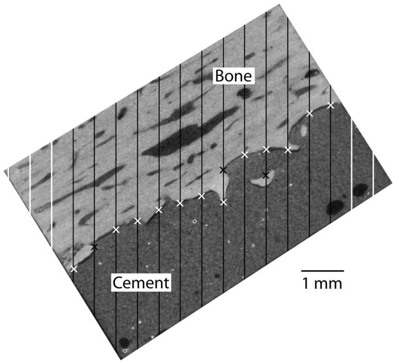
Stereology grid lines was projected through the CT scan images of the specimens at the four different loading angles. A thirty degree loading angle case is shown here and lines that cross the cement-bone interface (black) are included in the total line count. Points of apposition (black x) and points of proximity (white x) at the cement-bone interface are shown for one plane of the interface.
Statistical Analysis
To determine if compliance changed with loading angle, the slope of compliance versus loading angle was calculated for each specimen. From this, a t-test was performed to determine if the slope was different from zero. To determine if the interface was more compliant in the tensile direction compared to the compression direction for all loading angles, a tension to compression compliance ratio was calculated. A t-test with correction for multiple sampling was performed to determine if the ratio was greater than 1.0 for each loading angle. Similarly, a coupled transverse to axial compliance ratio was calculated to provide a relative measure of the magnitude of out of plane micro-motion. Simple linear regression analysis was used to assess the correlation of each of the morphology measurements with interface compliance. Following this, a step-wise regression was used to determine significant factors that contribute to interface compliance including morphological, source of bone, and loading angle. For all analyses, compliance was transformed with a log transformation to normalize distributions.
RESULTS
Descriptive statistics for the mechanical and morphological outcome measures a re presented as laboratory prepared and postmortem groups (Table 2). The morphology of the postmortem specimens was substantially different from the laboratory prepared specimens. While the interdigitation depth (p=0.50) and intersection fraction (p=0.87) were not different between the two groups, there was significantly less contact index (p<0.0001) and contact area (p<0.0001) between cement and bone for the postmortem retrieval specimens. An example of these differences is shown in Figure 4 where there was similar interdigitation between the two specimen types but much less cement-bone contact for the post-mortem retrieval.
Table 2.
Compliance and morphology data collected for the laboratory prepared and postmortem cement-bone interfaces. Results are shown for 24 laboratory prepared (4 loading angles × 6 specimens) and 23 postmortem (4 loading angles × 6 specimens, excluding PM1 loaded at 90º). The interdigitation depth was calculated for the 0° loading case only. Mean, standard deviation (SD) and range values are shown.
| Parameter | Laboratory Prepared (n=24) | Postmortem (n=23) | ||
|---|---|---|---|---|
| Mean (SD) | Range | Mean (SD) | Range | |
| Tensile axial compliance (mm/MPa) | 0.0156 (0.008) | 0.0033–0.037 | 0.052 (0.039) | 0.0158–0.196 |
| Compressive axial compliance (mm/MPa) | 0.0146 (0.007) | 0.0016–0.027 | 0.044 (0.028) | 0.0133–0.109 |
| Tension/Compression axial compliance ratio | 1.108 (0.34) | 0.68–2.12 | 1.140 (0.32) | 0.77–1.86 |
| Coupled Transverse compliance (mm/MPa) | 0.0011 (0.0009) | 2.4×10⁻⁵–0.0035 | 0.005 (0.006) | 1.12×10⁻⁵–0.027 |
| Coupled Transverse/Axial compliance ratio | 0.115 (0.115) | 0.0157–0.48 | 0.142 (0.101) | 0.0054–0.38 |
| Contact Index (CI) | 1.208 (0.61) | 0.35–3.1 | 0.57 (0.31) | 0.052–1.39 |
| Contact Area (CA, mm2) | 22.97 (14.8) | 6.5–53.8 | 10.8 (5.8) | 2.02–21.6 |
| Intersection index (II) | 1.92 (0.65) | 1.22–3.79 | 1.89 (0.69) | 0.94–3.12 |
| Interdigitation Depth (ID, mm) | 0.234 (0.174) | 0.062–0.43 | 0.375 (0.454) | 0.009–0.990 |
Figure 4.

Micro-CT images of the cement-bone interfaces from laboratory prepared (A, LP1) and postmortem retrieval (B, PM5) specimens. While the laboratory prepared specimen has extensive cement-bone contact at the interface, gaps are more prevalent between the cement and bone in the retrieval specimen. Regions indicative of bony resorption are designated by arrows.
Tests were completed for all specimens at all loading angles except for PM1 that failed prior to completing the 90° loading angle con figuration. It should be noted that PM1 had the lowest applied stress and was the most compliant of all the specimens, and thus was likely the weakest specimen. Axial compliance did not depend on loading angle (Figure 5A) for laboratory prepared (p=0.96) o r postmortem specimens (p=0.62) (statistical analysis is shown in Table 3). The variance between specimens (0.78 coefficient of variation, calculated as the standard deviation divided by the mean) was much greater than the variance within specimens at the four different loading angles (0.28 average coefficient of variation, range: 0.036 to 0.92).
Figure 5.

Axial tensile compliance (A) and transverse compliance (B) of the cement-bone interface as a function of loading angle for postmortem (solid black lines) and laboratory prepared specimens (dashed red lines).
Table 3.
The slope of the tensile compliance to loading angle response was calculated for laboratory prepared and postmortem specimens. A two-tailed t-test was performed to determine if the slope was different from 0. A zero slope would indicate that loading angle did not influence compliance. Mean, standard deviation (SD) and range values are shown.
| Specimen Source | Mean (SD) ((mm/MPa)/degree) | Range ((mm/MPa)/degree) | P-value with Bonferroni Correction |
|---|---|---|---|
| Laboratory Prepared (n=6) | 6.1 × 10⁻⁵ (0.0027) | −0.0049–0.0026 | 0.96 |
| Postmortem (n=6) | −0.0025 (0.0047) | −0.0113–0.0020 | 0.62 |
| Combined (n=12) | −0.0011 (0.0039) | −0.0113–0.0026 | 0.62 |
The cement-bone interface was more compliant under tensile than compressive loading (Table 4) at the 0° loading angle only (p=0.024). The coupled transverse to axial compliance ratio, which is a measure of the coupled motion, was small for laboratory prepared (0.115±0.115) and postmortem specimens (0.142±0.101). The transverse compliance (Figure 5B) did not have any clear relationship with loading angle.
Table 4.
The ratio of axial tensile to axial compressive compliance of the cement-bone interface as a function of loading angle for the 12 test specimens. A one-tailed t-test was performed to determine if mean value was greater than 1.0. Mean, standard deviation (SD) and range values are shown.
| Loading Angle (deg) | Mean (SD) | Range | P-value with Bonferroni Correction |
|---|---|---|---|
| 0 | 1.36 (0.43) | 0.89–2.12 | 0.024 |
| 30 | 1.17 (0.32) | 0.68–1.86 | 0.134 |
| 60 | 0.99 (0.18) | 0.82–1.51 | 0.97 |
| 90 | 0.94 (0.09) | 0.77–1.08 | 0.97 |
Compliance was inversely proportional to Contact Index (r2=0.50, p<0.0001), Contact Area (r2=0.30, p<0.0001), and Intersection Index (r2=0.12, p=0.018). Using a stepwise regression model, both Contact Index (p<0.0001), and bone source (lab prepared or postmortem) (p =0.0017) contributed to estimates of interface compliance (r2 = 0.65). Interestingly, for the same Contact Index, the postmortem specimens were more compliant than the laboratory prepared specimens (Figure 6). The interdigitation depth did not correlate with axial compliance (r2=0.08, p=0.36).
Figure 6.

Axial tensile compliance as a function of Contact Index for lab prepared and post mortem specimens.
The confirmation compliance test at 30° degrees was compared to the initial 30° compliance test for both tension and compression loading (22 total tests from 11 specimens with full runs with both tensile and compressive compliance measurements). Overall, the confirmation to original compliance ratio was 1.03 (0.15 SD) with 19 of the 22 tests having confirmation to original compliance ratios of less than 110%. Interestingly, half of the tests had confirmation compliance s that were less than the original compliance. Two specimens with confirmation to original compliance ratios greater than 110% (115% in the compression direction and 129% and 152% in the tension direction) were from the most compliant specimens.
DISCUSSION
The results of this study suggest that the magnitude of interface micromotion from an externally applied load does not depend on the angle at which that load is applied. Further, coupled transverse micromotions are small. As described previously [8, 10], there is local sliding and opening of the interface between the interdigitated cement and bone that is responsible for this micromotion. The finding that interface compliance (inverse stiffness) is invariant to loading direction might seem in conflict with previous reports that indicated that interface strength is greater in shear than in tension (Mann et al., 1999). However, if we compare the stiffness versus strength response in tension (Mann et al., 2008) with that from the shear direction (Mann et al., 2009) (Figure 7), we find that for the same stiffness (or compliance), the interface is stronger in shear than in tension. For the data presented in Figure 7, the ratio o f slopes of the strength versus stiffness linear regression is 4.02:1 (shear to tension) indicating that for the same interface stiffness, a specimen would be 4 times stronger in shear than in tension. It should be noted that the shear loading experiments were from a relatively small sample population and that more data should be collected to provide a more complete description of the strength to stiffness response in the shear direction using both lab prepared and postmortem retrieved specimens.
Figure 7.

Relationship between interface stiffness and interface strength compiled from previously reported data (Mann et al., 2008; Mann et al., 2009).
An alternative approach to determine the multi-axial response of the cement-bone interface is to perform micromechanical finite element analyses. With this approach detailed finite element models of the cement and bone are created that capture the local interface morphology. In addition, a failure criterion for the cement and bone can be used such that tests to failure tests on the same specimen can be conducted in tension and shear. Using this approach for two finite element meshes with different levels of interdigitation based on laboratory prepared specimens, Waanders et al. (2010) found that the cement-bone interface was, on average, slightly less compliant (tension:shear ratio of 0.87) in 0° (tension) than 90° (shear) loading angles. In the current experimental study, we found that for 12 different specimens that the ratio of 0° to 90° loading angle compliance was 0.998.
Modeling of the cement-bone interface in cemented hip replacement has evolved substantially over the last several decades. Initial work focused on the effects of decoupling of the cement from the bone through inclusion of a fibrous tissue layer at the cement-bone interface (Brown et al., 1988; Waide et al., 2004). The addition of fibrous tissue in these models resulted in changes in distribution and magnitude of bone and cement stresses from the standard bonded condition at the cement-bone interface. However, these models were not capable of simulating the actual failure process at the interface. More recently, efforts have been made to model the failure response of the cement-bone interface using damage mechanics approaches (Moreo et al., 2007; Moreo et al., 2006; Perez et al., 2009; Perez and Palacios, 2010). These studies showed that the cement-bone interface plays an important role in the failure process of the cemented stem construct. The results from the present study could be used to improve the accuracy of these damage models through implementation of a high compliance layer with isotropic deformation properties (invariant to loading direction for the same applied stress). The magnitude of compliance could be modified from a highly interdigitated state with relatively low compliance to a state where there is little cement-bone contact with relatively high compliance. The evolution of the interface from a highly interdigitated state, to a loose state could also be explored (Giori et al., 1995; Lennon and Prendergast, 2009).
The main limitation to this study is that specimens were not loaded to failure, so that the full failure response in each loading direction was not determined. As described above, one approach to generate a full failure response is to perform finite element (FE) simulations to failure of the same specimen with different loading directions. However, FE simulations are limited by the ability to capture all features of the failure response. The concurrence between the experimental findings here and the micromechanical FE results to failure suggests that the models are capable of capturing the primary failure mechanisms. In addition to single cycle loading limitations, the multi-axial fatigue loading response cannot be addressed with this experimental approach. There is the possibility that the weakest (most compliance) specimens could have bee n damaged during the rotation to the different loading angle. Removal of the two most compliant specimens from the data set did not affect the overall conclusion that compliance did not depend on loading angle.
Recently, our group showed that postmortem retrieval specimens have much less contact between cement and bone when compared to laboratory prepared specimens (Miller et al., 2010). However, in the previous testing of laboratory prepared specimens, a side plate was not used to support the interface prior to loading. In some cases, weak specimens would fail during set up in the loading grips. In the current study, because side plates were attached between the cement and bone during preparation, the weaker laboratory prepared specimens remained intact during the experimental setup and could be tested. As such, data is now presented that indicates that for the same interface Contact Index, postmortem retrieval specimens are more compliant than laboratory prepared specimens. The reason for this is unclear but could be due to changes in the stiffness (modulus) of the bone in contact with t he cement or some other morphology parameters not captured by the Contact Index. Additional work is needed to determine the cause of this discrepancy.
Interdigitation depth was not found to correlate with interface compliance in the present study. Performing mixed-mode tests on cement-bovine bone interfaces with an average interdigitation depth of 0.51 mm, Wang et al. (2010) found a poor correlation (r2=0.16) between interdigitation depth and interface strength. In the current study, the average interdigitation depth was also small (0.3 mm). It is possible that a much wider range of interdigitation depth would reveal a relationship between interface compliance and strength.
Postmortem retrieval specimens are more compliant and have less contact between cement and bone when compared to laboratory prepared specimens. While laboratory prepared specimens can be more easily obtained, they appear to only represent behavior that would exist in the immediate post-operative condition. The biological response to implantation clearly changes the morphology of fixation with reduced contact between cement and bone. There is also clear evidence of bony resorption from regions that had originally been interdigitated (Figure 4). In the development of bench-top preclinical models for evaluation of new implant designs, conditions that simulated the in vivo situation would be preferable, but also may be harder to achieve with experimental models.
In terms of clinical relevance, these results indicate that interface compliance increases following in vivo service. This is due to a loss of contact between cement and bone. In addition, there appears to be an additional increase in compliance for postmortem specimens for the same amount of contact between cement and bone. The mechanism for this is unclear, but could be due to other changes at the bone-cement interface.
Acknowledgments
This work was funded by the National Insititutes of Health (NIH AR42017).
Footnotes
Publisher's Disclaimer: This is a PDF file of an unedited manuscript that has been accepted for publication. As a service to our customers we are providing this early version of the manuscript. The manuscript will undergo copyediting, typesetting, and review of the resulting proof before it is published in its final citable form. Please note that during the production process errors may be discovered which could affect the content, and all legal disclaimers that apply to the journal pertain.
References
- Arola D, Stoffel KA, Yang DT. Fatigue of the cement/bone interface: the surface texture of bone and loosening. J Biomed Mater Res B: Appl Biomat. 2006;76:287–297. doi: 10.1002/jbm.b.30364. [DOI] [PubMed] [Google Scholar]
- Bishop NE, Schoenwald M, Schultz P, Puschel K, Morlock MM. The condition of the cement mantle in femoral hip prosthesis implantations--a post mortem retrieval study. Hip Int. 2009;19:87–95. doi: 10.1177/112070000901900202. [DOI] [PubMed] [Google Scholar]
- Brown TD, Pedersen DR, Radin EL, Rose RM. Global mechanical consequences of reduced cement/bone coupling rigidity in proximal femoral arthroplasty: A three-dimensional finite element analysis. J Biomech. 1988;21:115–129. doi: 10.1016/0021-9290(88)90005-x. [DOI] [PubMed] [Google Scholar]
- Giori NJ, Ryd L, Carter DR. Mechanical influences on tissue differentiation at bone-cement interfaces. J Arthroplasty. 1995;10:514–522. doi: 10.1016/s0883-5403(05)80154-8. [DOI] [PubMed] [Google Scholar]
- Lennon AB, Prendergast PJ. The cement-bone interface: Is it susceptible to damage adaptive remodeling?. 4th European Conference of the International Federation for Medical and Biologicial Engineering; Springer Verlag; 2009. pp. 1990–1993. [Google Scholar]
- Mann KA, Miller MA, Cleary RJ, Janssen D, Verdonschot N. Experimental micromechanics of the cement-bone interface. J Orthop Res. 2008;26:872–879. doi: 10.1002/jor.20575. [DOI] [PMC free article] [PubMed] [Google Scholar]
- Mann KA, Miller MA, Race A, Verdonschot N. Shear fatigue micromechanics of the cement-bone interface: An in vitro study using dig ital image correlation techniques. J Orthop Res. 2009;27:340–346. doi: 10.1002/jor.20777. [DOI] [PMC free article] [PubMed] [Google Scholar]
- Mann KA, Werner FW, Ayers DC. Mechanical strength of the cement-bone interface is greater in shear than in tension. J Biomech. 1999;32:1251–1254. doi: 10.1016/s0021-9290(99)00107-4. [DOI] [PubMed] [Google Scholar]
- Miller MA, Eberhardt A, Cleary RJ, Verdonschot N, Mann KA. Micro-mechanics of post-mortem retrieved cement-bone interfaces. J Orthop Res. 2010;28:170–177. doi: 10.1002/jor.20893. [DOI] [PMC free article] [PubMed] [Google Scholar]
- Moreo P, Garcia-Aznar JM, Doblare M. A coupled viscoplastic rate-dependent damage model for the simulatio n of fatigue of cement-bone interfaces. Int J Plasticity. 2007;23:2058–2084. [Google Scholar]
- Moreo P, Pérez MA, García-Aznar JM, Doblaré M. Modelling the mixed-mode failure of cement-bone interfaces Eng. Fract Mech. 2006;73:1379–1395. [Google Scholar]
- Perez MA, Garcia-Aznar JM, Doblare M. Does increased bone-cement interface strength have negative consequences for bulk cement integrity? A finite element study. Ann Biomed Eng. 2009;37:454–466. doi: 10.1007/s10439-008-9616-7. [DOI] [PubMed] [Google Scholar]
- Perez MA, Palacios J. Comparative finite element analysis of the debonding process in different concepts of cemented hip implants. Ann Biomed Eng. 2010;38:2093–2106. doi: 10.1007/s10439-010-9996-3. [DOI] [PubMed] [Google Scholar]
- Tong J, Wong KY, Lupton C. Determination of interfacial fracture toughness of bone-cement interface using sandwich Brazilian disks. Eng Fract Mech. 2007;74:1904–1916. doi: 10.1016/j.engfracmech.2006.02.014. [DOI] [PMC free article] [PubMed] [Google Scholar]
- Waanders D, Janssen D, Mann KA, Verdonschot N. The mechanical effects of different levels of cement penetration at the cement-bone interface. J Biomech. 2010;43:1167–1175. doi: 10.1016/j.jbiomech.2009.11.033. [DOI] [PMC free article] [PubMed] [Google Scholar]
- Waide V, Cristofolini L, Stolk J, Verdonschot N, Boogaard GJ, Toni A. Modeling the fibrous tissue layer in cemented hip replacements: experimental and finite element methods. J Biomech. 2004;37:13–26. doi: 10.1016/s0021-9290(03)00258-6. [DOI] [PubMed] [Google Scholar]
- Wang JY, Tozzi G, Chen J, Contal F, Lupton C, Tong J. Bone-cement inter facial behaviour under mixed mode loading conditions. J Mech Beh Biomed Mat. 2010;3:392–398. doi: 10.1016/j.jmbbm.2010.03.001. [DOI] [PubMed] [Google Scholar]