Abstract
An experimental study of picosecond pulse amplification in a gyrotron-traveling wave tube (gyro-TWT) has been carried out. The gyro-TWT operates with 30 dB of small signal gain near 140 GHz in the HE06 mode of a confocal waveguide. Picosecond pulses show broadening and transit time delay due to two distinct effects: the frequency dependence of the group velocity near cutoff and gain narrowing by the finite gain bandwidth of 1.2 GHz. Experimental results taken over a wide range of parameters show good agreement with a theoretical model in the small signal gain regime. These results show that in order to limit the pulse broadening effect in gyrotron amplifiers, it is crucial to both choose an operating frequency at least several percent above the cutoff of the waveguide circuit and operate at the center of the gain spectrum with sufficient gain bandwidth.
Gyrotrons are a form of electron cyclotron maser capable of producing kilowatts to megawatts of output power in the microwave, millimeter wave, and terahertz bands [1–4]. In recent years gyrotron amplifiers have demonstrated high output power levels with significant gain bandwidths [5–7]. One important application of millimeter waves is in spectroscopy, where coherent pulses on a subnanosecond or picosecond time scale are needed for optical pumping of molecular states. The pulses must be shorter than the relaxation time, typically requiring subnanosecond (or picosecond) pulse lengths [8]. Picosecond microwave pulses have been demonstrated in a vacuum electron device by superradiance [9], but such pulses cannot be used for spectroscopy. Subnanosecond pulses must contain a spectral bandwidth exceeding the transform limit, that is, exceeding 1 GHz. In the conventional microwave bands, at frequencies of one to several GHz, the required gain bandwidth to amplify such picosecond pulses is generally not available, since the GHz bandwidth is a large fraction of the carrier frequency. In recent years, high power, wideband amplifiers in the millimeter wave band have been developed that are suitable for amplifying picosecond pulses. For example, a form of klystron called an extended interaction klystron has been developed at 95 GHz with a gain bandwidth of about 1 GHz. This amplifier has been used to successfully amplify 1 kW output pulses as short as 800 picoseconds [10]. A gyrotron-traveling wave tube (gyro-TWT) at 95 GHz has been demonstrated with a gain bandwidth of 6.5 GHz at an output power level of 2 kW [7]. This gyro-TWT could, in principle, be used to amplify a 150 ps pulse. To our knowledge, amplification of picosecond pulses has not been tested with these or other powerful wideband gyro-amplifiers. Because of the possibility of distortion in amplification of picosecond pulses, detailed studies are needed of the amplification process in such devices. In this paper, we report a detailed study of amplification of pulses as short as 400 ps in a 1 kW, 140 GHz gyro-TWT with a gain bandwidth exceeding 1 GHz. To our knowledge, this is the first report of amplification of pulses of such short temporal duration in a vacuum electron device operating at conventional voltages (≲100 kV). This amplifier will ultimately be applied to coherent molecular spectroscopy. Therefore, the ability of the gyro-TWT to faithfully amplify very short pulses without distortion must be tested, since it is important to the application. Second, we are interested in comparing theory and experiment in the dispersion of picosecond pulses in a vacuum electron device amplifier. In this research, we have intentionally driven the amplifier with pulses as short as 400 ps, which contains frequencies over a 2.5 GHz bandwidth, about twice the amplifier’s inherent gain bandwidth. A study of the nature of the output pulses reveals the different sources of pulse distortion and broadening.
Amplification is achieved in a gyro-TWT by a convective instability supported by a mildly relativistic annular gyrating electron beam and a transverse electric mode in a waveguide immersed in a strong static axial magnetic field (B0). The grazing intersection between the dispersion of the cyclotron mode on the electron beam and a transverse electric waveguide mode near the waveguide cutoff results in high gain and moderate bandwidth. The beam mode and the waveguide mode dispersion relations are expressed as
| (1) |
| (2) |
where ω is the frequency, Ω = eB0/me is the nonrelativistic cyclotron frequency, e and me are the charge and the rest mass of the electron, γ is the relativistic mass factor, s = 1 is the cyclotron harmonic number, kz and k⊥ are the longitudinal and transverse propagation constants, respectively, of the waveguide mode, υz is the axial velocity of the electrons, and c is the velocity of light. From Eq. (2) it follows that near waveguide cutoff, the group velocity can be described as where υg is the group velocity, δω = ω − ωc0 and ωc0(= k⊥c) is the cutoff frequency.
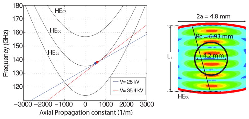
In a gyro-TWT gain occurs near the intersection of the beam line [Eq. (1)] and the waveguide dispersion line [Eq. (2)] as shown for the HE06 mode of a confocal waveguide in Fig. 1. The gyro-TWT has produced a 3 dB gain bandwidth of over 1.5 GHz (1.1%) with a peak power of 570 W from a 38.5 kV, 2.5 A electron beam [11]. A maximum output power of 0.82 kW was achieved. By adjusting such parameters as the main magnetic field, the electron beam voltage, and the voltage on the control anode, the beam line may be moved from close to the cutoff position to much farther from the cutoff position.
FIG. 1.
(color online). Dispersion diagram of HE06 gyro-TWT in a confocal waveguide (left) and cross sectional view (right). The annular electron beam has a 4.2 mm diameter.
The amplifier circuit is an overmoded quasioptical confocal waveguide consisting of three 7 cm-long gain sections separated by two 3.7 cm severs. Figure 1 shows a cross section of the confocal waveguide with the waveguide rails of 6.93 mm radius separated by a distance L⊥ of 6.93 mm. The gyro-TWT operates in the HE06 mode. The electron beam is tuned to a grazing intersection with the HE06 waveguide mode. The beam line intersection with the HE05 mode can lead to backward wave oscillations limiting the beam current in the circuit.
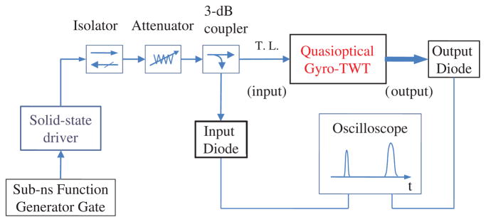
Figure 2 shows a schematic of the picosecond pulse amplifier experiments. The picosecond drive pulses are generated by a solid-state source consisting of an X band mixer switch with an up-converter to 35 GHz and a Virginia Diodes, Inc. ×4 multiplier to 140 GHz [12]. The driver input at the gyro-TWT after the 3 dB directional coupler as shown in Fig. 2 was approximately 16 mW over the 135–143 GHz range in pulses as short as 400 ps. The detector diode outputs were measured by an oscilloscope with a 10 GHz bandwidth and a 40 gigasample/s sampling rate. The relative temporal responses of the input diode and the output diode were tested and compared while simultaneously connected to a common directional coupler. The temporal responses of the two detector diodes from 400 ps to 1 ns agreed to within 5%. For this study, the gyro-TWT was first operated in longer pulses, on the microsecond scale, to establish the gain and bandwidth in long pulse operation, prior to the short pulse tests. Results were obtained at voltages of 35.4 and 28 kV, with 1.8 A beam current and 5.01 T magnetic field.
FIG. 2.
(color online). Schematic diagram of the picosecond pulse amplification in a quasioptical gyro-TWT.
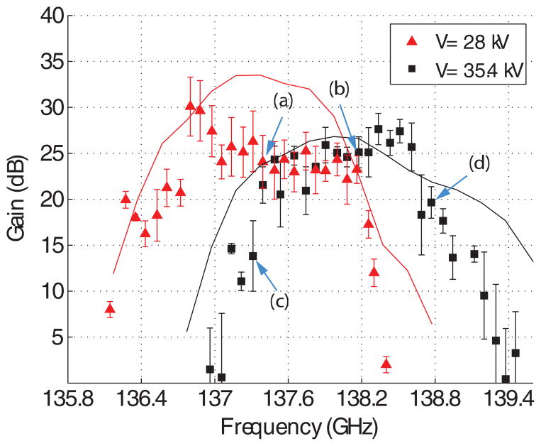
Figure 3 shows the theoretical and measured gain bandwidth for these two operating conditions. The measured gain was as high as 30 dB and the output power was about 10 W, which is well within the linear gain regime. The linear regime operation was verified by measuring the input power vs output power over a range of input power values. Simulations of the gyro-TWT were performed using the computer code MAGY [13] with a beam velocity ratio α = 1.1 and 1.4 and a perpendicular velocity spread of 9.5% and 12% for 35.4 and 28 kV, respectively. The measured data points in Fig. 3 are in reasonable agreement with theoretical predictions. The 3 dB bandwidths of both cases are about 1.2 GHz. Following the microsecond gain experiments, we conducted tests of the gain and dispersion of the gyro-TWT with picosecond input pulses. The pulse in the interaction circuit is expected to suffer from two dispersive effects: waveguide dispersion from operating near the cutoff frequency of the confocal waveguide structure and gain dispersion from the bandwidth-limited nature of the amplifier. Waveguide dispersion occurs because of the frequency dependence of the group velocity, as can be seen from Eq. (2) and Fig. 1. It has a significant effect because the frequency of the pulse is very close to the cutoff of the waveguide (kz ≪ k). Gain dispersion is also observed for the pulse lengths of interest due to the fact that the spectral width of the pulse is on the order of or greater that the bandwidth of the gyro-amplifier.
FIG. 3.
(color online). Measured and calculated gain-bandwidth curves for beam voltages of 35.4 and 28 kV. The points labeled (a), (b), (c), and (d) correspond to the labels in Fig. 6 below.
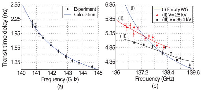
In order to benchmark our procedures, we measured the dispersion of picosecond pulses in an empty WR4 (rectangular 1.092 × 0.546 mm) waveguide with cutoff frequency of 139.25 GHz. In this case, only waveguide dispersion, as given by Eq. (2), is present. In Fig. 4(a) pulses passing through 10 cm of the WR4 waveguide showed pulse transit time delays and pulse broadening effects.
FIG. 4.
(color online). Measured (dots) and calculated (solid line) transit time delay of 500 ps pulses in (a) 10 cm-long WR4 waveguide with a cutoff frequency of 139.25 GHz and (b) the 28.4 cm gyro-TWT confocal waveguide structure with a cutoff frequency of 135.0 ± 0.3 GHz.
A waveguide filled with an active medium (the electron beam in this case) shows an additional dispersive effect due to that medium, especially near cyclotron resonance. In Fig. 4(b) we show the measured transit time delay for 500 ps pulses traveling through the 28.4 cm confocal waveguide structure of the gyro-TWT at two different voltages as a function of frequency. Theory curves are also shown; the theory is derived and explained below. In Fig. 4(b), (I) is the calculated transit time delay in the gyro-TWT including only waveguide dispersion, that is, for the empty waveguide with no electron beam present. (II) and (III) are the measured and calculated transit time delay of picosecond pulses in the gyro-TWT for two different beam voltages, namely, 28 and 35.4 kV. These results show that the active medium, the electron beam, has a significant effect on the transit time. The pulse interaction with the electron beam can be described by
| (3) |
where A+ is the pulse envelope, kz is the axial wave number, and Ns is a normalization constant for the waveguide mode and Es is the transverse electric field [14,15]. If the amplifier is operating in the linear regime the right-hand side of Eq. (3) can be approximated as
| (4) |
where G(ω), the linear gain over the spectral range of the pulse, can be determined from theory or from experiment [16], as in Fig. 3. Similar to optical systems [17–19], it is convenient to deal with the dispersion in the frequency domain where Eqs. (3) and (4) become
| (5) |
where a(z, ω) is the frequency spectrum of the pulse. The effects of dispersion can be modeled as distortions to the frequency spectrum of the pulse as it travels through the interaction circuit. Theoretical broadening curves were generated by observing the broadening of Gaussian pulses as they traveled through the circuit. For a pulse A(z0, t) at the start of the circuit, the frequency spectrum is given by
| (6) |
For the Fourier transform of a pulse, if we amplify and advance the phase of every spectral component, it will be equivalent to propagating the pulse through the circuit. Performing an inverse Fourier transform on this new spectrum
| (7) |
produces the output pulse in the time domain. Equation (7) shows that gain dispersion plays a significant role in broadening of picosecond pulses when the spectral bandwidth of the amplified pulse is comparable to the gain bandwidth of the gyro-TWT. Equation (7) was used to calculate the results shown in Fig. 4(b). Those results are in excellent agreement with the experimental data at the two different operating voltages.
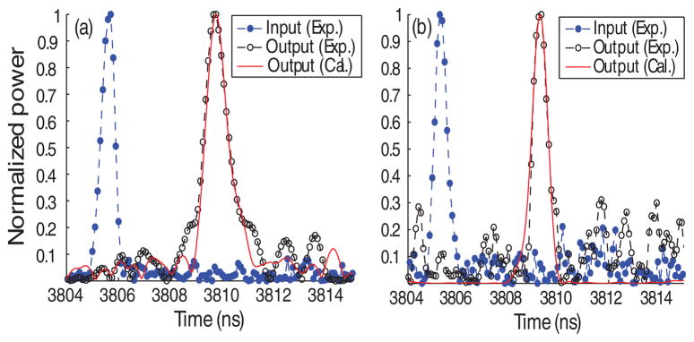
Figure 5 shows an example of the measured temporal shapes of input and output pulses as measured by the diodes shown in the schematic of Fig. 2. Operating at 35.4 kV with a 600 ps input pulse, the detected output pulse envelopes vary with frequency in good agreement with the numerical simulation results of Eq. (7). From Fig. 5, we can clearly see that for a subnanosecond pulse traversing an interaction space with a gain bandwidth of 1.2 GHz, the output pulse will suffer significant pulse broadening in the time domain.
FIG. 5.
(color online). Pulse shapes for an input pulse of 580 ps at the 35.4 kV. The output pulses at (a) 137.3 GHz and (b) 138.13 GHz have measured widths of 1045 ps and 660 ps, respectively.
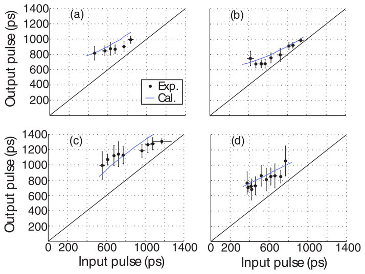
Figure 6 shows experimental results and theoretical calculations of the output pulse width vs input pulse width for the gyro-TWT, showing clear evidence of pulse broadening effects. For very long pulses (not shown in the figure), greater than a few nanoseconds, there is no pulse broadening, as expected; the output pulse has the same width as the input pulse. Results are presented for the two beam voltages for which the gain spectra are shown in Fig. 3. Figures 6(a) and 6(b) show pulse broadening curves at the center of the gain spectrum where the broadening due to gain narrowing should be minimized. We also find that even though both operating points have a similar gain bandwidth, for the case of Fig. 6(a) the broadening is more severe than Fig. 6(b). Theory shows that this arises because the frequency of the pulse in case (a) is 0.75 GHz closer to cutoff, thus increasing the waveguide dispersion contribution to the broadening. Figures 6(b)–6(d) were produced for the same beam voltage, but for different input pulse frequencies. Figure 6(b) displays the least broadening because it is centered in the gain spectrum of the amplifier at 138.13 GHz. Figure 6(c) is both 0.85 GHz below the center of the gain spectrum and closer to cutoff. As a result, pulse broadening arises from both gain narrowing and the proximity to waveguide cutoff, resulting in very large broadening. At the 138.8 GHz operating frequency of Fig. 6(d), pulse broadening is also worse than Fig. 6(b) because this point is 0.65 GHz above the center of the gain spectrum, causing gain narrowing. Theoretical calculations of output pulse width vs input pulse width were carried out for the four cases shown in Fig. 6 using Eq. (7), based on the experimentally measured gain spectra of Fig. 3. As seen in Fig. 6, the theoretical curves are in very good agreement with the experimental measurements.
FIG. 6.
(color online). Measured (dots) and calculated (solid lines) output pulse width after amplification as a function of input pulse width; (a) 28 kV and 137.4 GHz; (b), (c), and (d) are for 35.4 kV and (b) 138.13 GHz, (c) 137.3 GHz, and (d) 138.8 GHz.
In summary, the amplification of a sub-ns pulse in a 140 GHz gyro-TWT was successfully studied over a wide range of parameters. The experimental data of pulse broadening and transit time delay in the gyro-TWT are in good agreement with calculations in the linear gain regime that take into account the effects of waveguide dispersion and finite gain bandwidth. These results show that amplification of short pulses in a gyro-TWT will display significant broadening if the operating point is selected close to cutoff or close to the edge of the gain bandwidth. Based on the present results, it is crucial to both choose an operating frequency at least several percent above the cutoff of the waveguide circuit and to provide the necessary gain bandwidth of at least 1 GHz.
Acknowledgments
The authors gratefully acknowledge Ivan Mastovsky for his help in performing the experiments and Robert Griffin for helpful discussions of the application. This work was supported by National Institutes of Health (NIH), National Institute for Biomedical Imaging and Bioengineering (NIBIB) under Contracts No. EB001965 and No. EB004866.
References
- 1.Felch KL, et al. Proc IEEE. 1999;87:752. [Google Scholar]
- 2.Chu KR. Rev Mod Phys. 2004;76:489. [Google Scholar]
- 3.Glyavin M Yu, Luchinin AG, Golubiatnikov G Yu. Phys Rev Lett. 2008;100:015101. doi: 10.1103/PhysRevLett.100.015101. [DOI] [PubMed] [Google Scholar]
- 4.Notake T, et al. Phys Rev Lett. 2009;103:225002. doi: 10.1103/PhysRevLett.103.225002. [DOI] [PubMed] [Google Scholar]
- 5.Chu KR, et al. Phys Rev Lett. 1998;81:4760. [Google Scholar]
- 6.Bratman VL, et al. Phys Rev Lett. 2000;84:2746. doi: 10.1103/PhysRevLett.84.2746. [DOI] [PubMed] [Google Scholar]
- 7.Blank M, et al. Proceedings of the Joint 31st International Conference on IRMMW/14th International Conference on THz Electronics; Shanghai, China: IEEE; 2006. p. 198. [Google Scholar]
- 8.Bennati M, et al. J Magn Reson. 1999;138:232. doi: 10.1006/jmre.1999.1727. [DOI] [PubMed] [Google Scholar]
- 9.Ginzburg NS, et al. Phys Rev Lett. 1997;78:2365. [Google Scholar]
- 10.Bolton DR, et al. Electron Lett. 2007;43:346. [Google Scholar]
- 11.Joye CD, et al. IEEE Trans Electron Devices. 2009;56:818. doi: 10.1109/TED.2009.2015802. [DOI] [PMC free article] [PubMed] [Google Scholar]
- 12.Kim H, et al. Proceedings of the 34th International Conference on IRMMW-THz Waves; Busan, Korea: IEEE; 2009. (IEEE, Report No. TSE50.0072, 2009) [Google Scholar]
- 13.Botton M, et al. IEEE Trans Plasma Sci. 1998;26:882. [Google Scholar]
- 14.Kovalev NF, Palitsyn AV. Radiophys Quantum Electron. 2005;48:177. [Google Scholar]
- 15.Nusinovich GS. Introduction to the Physics of Gyrotrons. Vol. 6. Johns Hopkins Press; Baltimore: 2004. p. 126. [Google Scholar]
- 16.Chu KR, Lin AT. IEEE Trans Plasma Sci. 1988;16:90. [Google Scholar]
- 17.Agrawal GP. IEEE J Quantum Electron. 1991;27:1843. [Google Scholar]
- 18.Haus HA, Wong WS. Rev Mod Phys. 1996;68:423. [Google Scholar]
- 19.Haus HA. Waves and Fields in Optoelectronics. Vol. 6. Prentice-Hall; New York: 1984. p. 180. [Google Scholar]


