Abstract
Non-covalent interactions hold the key to understanding many chemical, biological, and technological problems. Describing these non-covalent interactions accurately, including their positions in real space, constitutes a first step in the process of decoupling the complex balance of forces that define non-covalent interactions. Because of the size of macromolecules, the most common approach has been to assign van der Waals interactions (vdW), steric clashes (SC), and hydrogen bonds (HBs) based on pairwise distances between atoms according to their van der Waals radii. We recently developed an alternative perspective, derived from the electronic density: the Non-Covalent Interactions (NCI) index [J. Am. Chem. Soc. 2010, 132, 6498]. This index has the dual advantages of being generally transferable to diverse chemical applications and being very fast to compute, since it can be calculated from promolecular densities. Thus, NCI analysis is applicable to large systems, including proteins and DNA, where analysis of non-covalent interactions is of great potential value. Here, we describe the NCI computational algorithms and their implementation for the analysis and visualization of weak interactions, using both self-consistent fully quantum-mechanical, as well as promolecular, densities. A wide range of options for tuning the range of interactions to be plotted is also presented. To demonstrate the capabilities of our approach, several examples are given from organic, inorganic, solid state, and macromolecular chemistry, including cases where NCI analysis gives insight into unconventional chemical bonding. The NCI code and its manual are available for download at http://www.chem.duke.edu/~yang/software.htm
I. INTRODUCTION
Non-covalent interactions are of critical importance in many chemical, biological, and technological systems. Protein-ligand interactions,1 self-assembly of nanomaterials,2 folding of proteins,3 and packing of molecular crystals,4 are controlled by a delicate balance of numerous, weak non-covalent interactions. The large sizes of the materials and structures of interest makes understanding non-covalent forces particularly difficult.
Accurately describing non-covalent interactions, including their spatial characteristics, constitutes the first step in the process of decomposing the complex balance of chemical forces. However, even this spatial characterization of interactions has generated controversy.5–8 Because of the size of many systems of interest, the most common approach to examining non-covalent interactions has been to assign van der Waals interactions (vdW), steric clashes (SC), and hydrogen bonds (HBs) in terms of pair-wise distances between atoms based on their vdW radii.9 This procedure, although lacking generality and giving rise to systematic errors (e.g., the length of HBs is generally overestimated), enables the rapid enumeration of non-covalent interactions.
More elaborate algorithms for mapping and analizing non-covalent interactions can be derived from the electronic and kinetic-energy densities. Indeed, the theory of atoms in molecules10 has been used to understand and to quantify weak interactions based on the electron density.10–12 This approach relies on the fact that critical points of the density (∇ρ=0) arise when atoms interact. If the interaction is bonding, the point is expected to be a first order saddle point. Many properties, including the density itself, its Laplacian (∇2ρ), and the kinetic-energy density, have been found to correlate with the interaction energy in vdW and HB complexes for families of related compounds.11,12 A parallel approach is based on the analysis of the electron localization function (ELF).13,14 This is a function of the electron density and the kinetic-energy density that was developed to highlight regions of electron localization (i.e., covalent bonds, lone pairs, etc.). HBs have also been studied using this approach, since the rise in the ELF value is proportional to the strength of the HB.15,16
Recently, we introduced a new approach to visualize non-covalent interactions, based on the analysis of the electron density and its reduced gradient, .17 This index was chosen for its ability to highlight interactions in the low-density regime (vide infra). The non-covalent interactions (NCI) index identifies interactions in a chemical system based solely on the electron density and its derivatives. Indeed, a similar approach has also been recently introduced to analyze covalent bonds, highlighting the ability of this type of function to identify all types of bonding situation.18 Here, we introduce a practical strategy for NCI analysis and visualization of weak interactions.
The paper first summarizes NCI theory. Next, the algorithms underlying NCI analysis are discussed. Finally, we apply the approach to chemical examples that span a diverse set of interaction types and system sizes. Emphasis is placed on the ability of the new approach to describe the bonding in systems under current debate.
Details of the computations are found in the supporting information. The software and manual may be downloaded at http://www.chem.duke.edu/~yang/software.htm
II. THEORETICAL BACKGROUND
The NCI analysis provides an index, based on the electron density and its derivatives, that enables identification of non-covalent interactions.17 It is based on a 2D plot of the reduced density gradient, s, and the electron density, ρ, where:
| (1) |
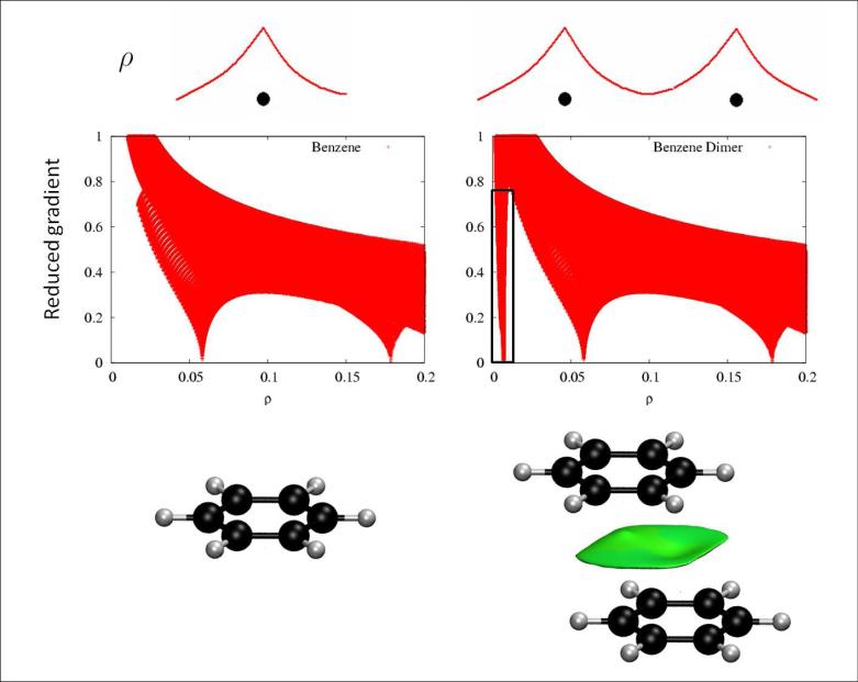
When a weak inter or intramolecular interaction is present, there is a crucial change in the reduced gradient between the interacting atoms, producing density critical points between interacting fragments (Figures 1a-b). Troughs appear in the s(ρ) plot associated with each critical point. Since the behavior of s at low densities is dominated by ρ, s tends to diverge except in the regions around a density critical point, where ∇ρ dominates, and s approaches zero. This fact is highlighted in Figures 1c-d, that shows that the main difference in the s(ρ) plots between a monomer and a dimer is the steep trough at low density. When we search for the points in real space giving rise to this feature, the non-covalent region clearly appears in the (supra)molecular complex (green isosurface in Fig. 1f).
FIG. 1.
a) Representative behavior of an atomic density. b) Appearance of a singularity when two atomic densities approach each other. c-d) Comparison of the reduced density behavior for benzene monomer and dimer; a singularity in s appears at low density values in the dimer case. e) Benzene monomer. f) Appearance of an intermolecular interaction surface in benzene dimer, associated with the additional singularity in the s(ρ) plot. The isosurface was generated for s = 0.7 au and ρ < 0.01 au.
Further analysis of the electron density in the troughs is required to assign the origins of these troughs (steric interactions, hydrogen bonds, etc.). The electron density values within the troughs are an indicator of the interaction strength. However, both attractive and repulsive interactions (i.e., hydrogen-bonding and steric repulsion) appear in the same region of density/reduced gradient space. To distinguish between attractive and repulsive interactions, we examine the second derivatives of the density along the main axis of variation.
Based on the divergence theorem,19 the sign of the Laplacian (∇2ρ) of the density indicates whether the net gradient flux of density is entering (∇2ρ < 0) or leaving (∇2ρ > 0) an infinitesimal volume around a reference point. Hence, the sign of ∇2ρ determines whether the density is concentrated or depleted at that point, relative to the surroundings. To distinguish between different types of weak interactions, one cannot use the sign of the Laplacian itself, because the sign is dominated by negative contributions from the nuclei.20 Instead, contributions to the Laplacian along the axes of its maximal variation must be analyzed. These contributions are the eigenvalues λi of the electron-density Hessian (second derivative) matrix, such that, ∇2ρ = λ1 + λ2 + λ3, (λ1 < λ2 < λ3). At the nuclei, all of the eigenvalues are negative, while away from them, λ3 > 0. In molecules, the λ3 values vary along the internuclear direction, while λ1 and λ2 report the variation of density in the plane normal to the λ3 eigenvector. Interestingly, the second eigenvalue (λ2) can be either positive or negative, depending on the interaction type. On the one hand, bonding interactions, such as hydrogen bonds, are characterized by an accumulation of density perpendicular to the bond, and λ2 < 0. Non-bonded interactions, such as steric repulsion produce density depletion, such that λ2 > 0. Finally, van der Waals interactions are characterized by a negligible density overlap that gives λ2 ≲ 0. Thus, analysis of the sign of λ2 enables us to distinguish different types of weak interactions, while the density itself enables us to assess the interaction strength.
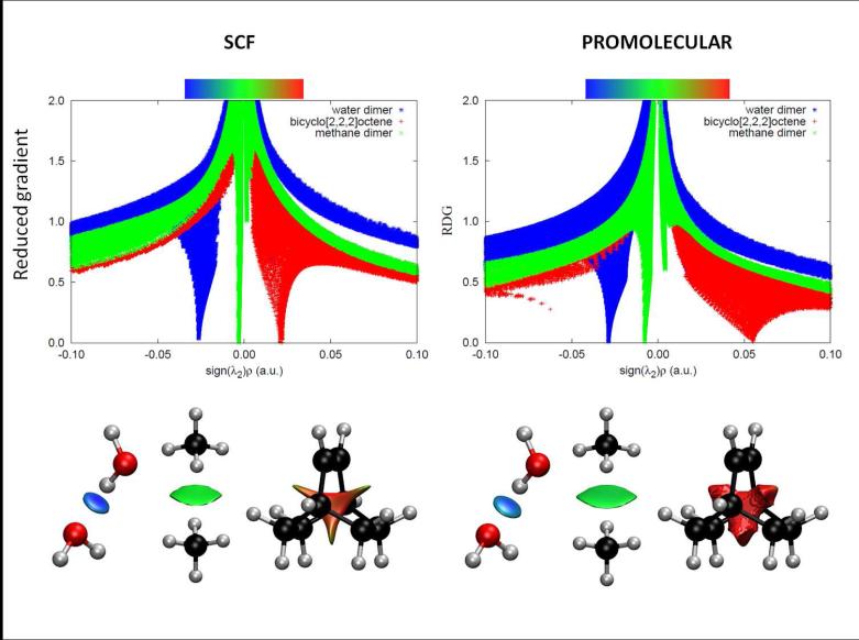
The dependence of on sign(λ2)ρ is shown in Figure 2a, which uses a modification of our earlier reduced gradient and density plots. The 3D plots resulting from using sign(λ2)ρ are shown in Figs. 2 bottom. The low-density, low-reduced gradient trough in the hydrogen-bonded water dimer now lies at negative values, indicative of an attractive interaction. Conversely, the low-density, low-gradient trough for the sterically-crowded bicyclo[2,2,2]octane molecule remains at positive values, indicating a repulsive interaction. Finally, the low-density, low-gradient trough for the dispersion-bound methane dimer is very near zero, with slightly sign(λ2) × ρ negative values of -0.0025 a.u., indicative of weak attraction.
FIG. 2.
Top: Overlapping troughs in s(ρ) plots can be distinguished when sign(λ2)ρ is used as the ordinate. Favorable interactions appear on the left, unfavorable on the right, and van der Waals near zero. The same s(ρ) features are obtained using self-consistent (left) and promolecular (right) calculations, with a shift toward negative (stabilizing) regimes. Bottom: Taking the shift in troughs into account (i.e. changing the cutoff), the isosurface shapes remain qualitatively unaltered for selected small molecules. Figures are shown for both SCF (left) and promolecular densities (right). NCI surfaces correspond to s = 0.6 au and a colour scale of −0.03 < ρ < 0.03 au for SCF densities. For promolecular densities, s = 0.5 au (water and methane dimers) or s = 0.35 au (bicyclo[2,2,2]octene) and the colour scale is −0.04 < ρ < 0.04 au.
III. ALGORITHMIC DETAILS
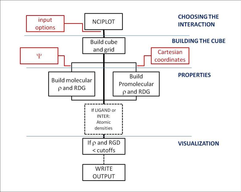
Figure 3 shows the protocol for visualizing non-covalent interactions in NCIPLOT. A detailed summary of the tasks associated with each routine is shown in Table I (cube construction, properties, visualization, and I/O flow).
FIG. 3.
Flow chart for program routines for non-covalent interactions visualization in NCIPLOT. Red labels highlight the information that can be input by the user, whereas black labels show the internal flow of information. The flow is divided into four main algorithmic parts: input, cube construction, properties, and visualization.
TABLE I.
NCIPLOT tasks and details of the input and output. The table is organized following the main algorithmic subdivisions of the flowchart (Figure 3): cube construction, properties, and visualization, as well as I/O flow. wfn file stands for the wavefunction file (wfn extension) commonly used for post-SCF analyses.
| MODULE | ROUTINE | TASK | INPUT | OUTPUT |
|---|---|---|---|---|
| MAIN | NCIPLOT | main routine | – – – – – | visualization |
| CUBE | CUBE | constructs cube and grid | geometry | cube, grid |
| I/O | TIMER | accumulates run times | process and resetting | elapsed times |
| GETARGS | get command | arguments | argument count | |
| GETDATE | extracts time and date | (operating system) | date and time | |
| ZATGUESS | provides atomic #s | atomic symbol | atomic # | |
| RWFN | stores wfn information | wfn file | wfn information | |
| RPROM | stores xyz information | xyz file | xyz information | |
| PROPS | PROPPROM | ρ,s(ρ) | ||
| CALCHESS | λ 2 | |||
| PROPWFN | ρ,s(ρ), λ2 | |||
| F012 | derivatives | |||
| PHI012 | summation over primitives | summation | ||
| PRI012 | construction of primitives | primitives | ||
| INDEX0 | angular momentum assignation | primitive type | Li | |
| RS | matrix diagonalization (eispack) | matrix | eigenvalues | |
The key data-flow details are highlighted in Fig. 3. The input of data is shown in red and its processing is indicated in black. Two basic types of data constitute the input: the density information (based on wavefunctions or molecular geometries) and the analysis options, which determine the non-covalent interactions to be plotted. Four algorithms analyze the data: (i) the selection of interactions (through the input), (ii) the construction of the cube and the grid (in CUBE, see table I), (iii) the calculation of properties at each point (utilizing a number of routines), and (iv) the calculation of visualization data (carried by the main routine, NCIPLOT). Since the input is keyword oriented, the program includes a number of parsing routines. These main features are discussed in the following sections.
A. Building the cube
Interaction analysis is based on examination of local properties on a cubic grid constructed within the program. This procedure was found to be extremely efficient for computing stable properties (as is the case of NCI, see Section III B).21 Furthermore, this approach enables us to discard contributions from high-density points in the construction of isosurfaces. The spatial region to be analyzed is determined, by default, in terms of the molecular geometry. Unless otherwise noted, a cube is constructed from the outermost x,y,z coordinates for all of the molecules in the input. An extra radial threshold in each direction is added to ensure that the isosurfaces are contained within the cube (no intermolecular interactions are expected in those regions, but isosurfaces can spread beyond the atoms). A practical threshold was defined as 2Å:
| (2) |
| (3) |
where xi = x, y, z. This step also eliminates spurious symmetry-related cancellations (e.g., if benzene were analyzed without this extra threshold, there would be no points along the C6 axis).
It can be useful to construct a user-defined cube or to analyze the interactions only around one point or molecule (vide infra). All of these options are implemented in the program and are described in the Supporting Information.
B. Properties
Density, reduced gradient, and λ2 values are calculated at each point on the grid. Densities can be obtained from quantum-mechanical calculations or from promolecular estimates. Topological features of the electron density in the weak interaction region are very stable with respect to the calculation method, to such an extent that these features are already contained in the sum of atomic densities .22,23 The molecular density computed from the sum of atomic contributions, also known as promolecular density (ρpro) is:
| (4) |
Promolecular densities lack the relaxation introduced in a SCF Hartree-Fock or DFT calculation; however, the promolecular densities are very useful for describing large biomolecular systems. In these systems, non-covalent interactions are crucial for describing the interplay of structure and reactivity.3 Because electron density calculations for these large systems are extremely expensive computationally, use of the promolecular density is an attractive option. When relaxed densities are compared to promolecular ones, a shift in the s(ρ) troughs is observed toward bonding regimes (see Figure 2 top). Specifically, a large shift toward smaller density values is observed in the troughs corresponding to regions of non-bonded overlap, introducing less repulsion and greater stability. However, once this shift is taken into account (by changing the density cutoff), results at the self-consistent and promolecular levels are qualitatively equivalent for all of the cases considered (see Figure 2, bottom).
SCF densities are constructed from the wavefunction information stored in the wfn file, whereas promolecular densities are constructed from the atomic positions stored in the xyz coordinate file(s). In order to store atomic densities, fully-numerical LSDA24 free-atomic densities were generated for the neutral atoms H to Ar, spherically averaged over space and summed over spins. Because atomic densities are piece-wise exponentially decaying for each shell of electrons, they were then fit to one (H, He), two (Li-Ne), or three (Na-Ar) Slater-type functions of the form ρat = ∑j cje−r/ζj. Once these densities are written as simple sums of exponential functions, the NCI surfaces can be calculated very efficiently for each (supra)molecule since all of the necessary data (ρ, s, λ2) can be obtained analytically.
C. Visualization: The cutoffs
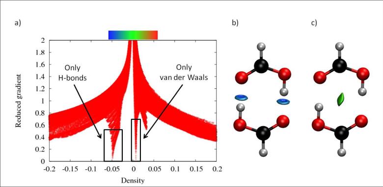
The ρ,s coordinates of the density troughs define the appropriate cutoffs for the non-covalent interactions. For example, a cutoff of ρ <0.05 au is appropriate for recovering the non-covalent interactions in the benzene dimer, including the non-bonding regions at the centre of each ring (Figure 1c-d). All points giving rise to ρ values above this threshold need to have their s values set to a large value. This enables the user to recover only the non-covalent interactions when s = S is plotted (for some isosurface value S) because this rescaling eliminates all points in density/reduced gradient space with greater density values and s < S (i.e., points with ρ >0.05 au and s < 0.5 au would also appear in the isosurface representation in Figure 1). Another example is provided in Figure 4. The formic acid dimer troughs appear at ρ=0.01 au for van der Waals contacts, and ρ=0.05 au for hydrogen bonds. If the cutoff is set to ρ=0.02 au, the isosurface will only recover the van der Waals interactions in the system (Fig. 4). Furthermore, placing a threshold for the interval ρ= [0.02-0.06] au enables the user to isolate the hydrogen bonds in a similar manner.
FIG. 4.
NCI analysis of formic acid dimer. a) s(ρ) plot for the SCF density. Peaks appear at ρ ≃0.01 au for vdW and ρ ≃0.05 au for hydrogen bonds. b) If the cutoffs are set at s = 0.7 au and ρ < 0.02 au, the isosurface only recovers the van der Waals interactions in the system. c) If the cutoffs are set at s = 0.5 au and 0.02 < ρ < 0.06 au, only the hydrogen bonds are displayed. The NCI colour scale is −0.06 < ρ < 0.06 au.
It is convenient, therefore, to perform a preliminary run, where only s(ρ) values are produced, and the user can use these data to determine optimal cutoffs. A second run can subsequently target the non-covalent interactions in a given molecule with no interference from other density regions. For this reason, the current implementation enables the user to decide which file types are to be output.
D. Input: Selectively displaying the interactions
In order to plot a certain interaction selectively, there are several constraints that can be applied to display the weak interactions of interest. Criteria for filtering the interactions include the strength of the interaction, its localization in space, and its nature (whether it is intermolecular or intramolecular). The details for each of these cases are described below.
Strength: it is possible to select the interaction in terms of its strength by the choice of cutoff parameters. Figure 4 uses the information in Section III C to plot only the van der Waals contact region in the formic acid dimer, while avoiding the hydrogen bonds. It is also possible to define an interval range, as in the formic acid dimer case, to identify only hydrogen bonds and exclude van der Waals interactions. An interval of the kind ρ= [0.02-0.06] au produces this result.
- Geometry: There are two possibilities when choosing a given interaction from its location in 3D space:
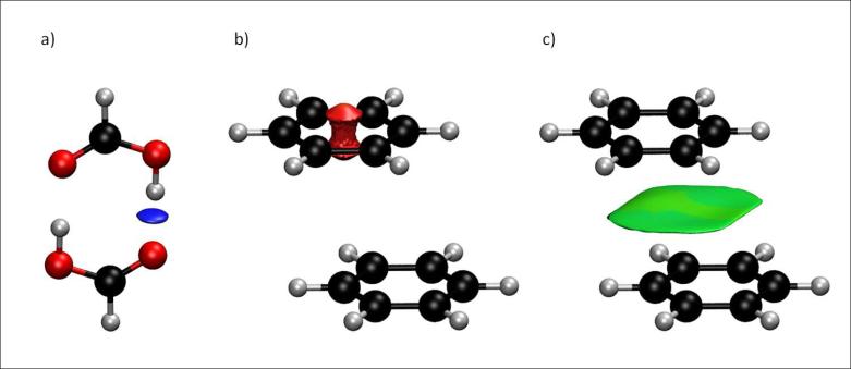
- An appropriate choice of the cube boundaries enables the selection of individual interactions (CUBE keyword in the Supporting Information). The cube in Figure 5a captures only one of the hydrogen bonds in the formic acid dimer. This option is especially suitable if there are several interactions of the same type, but only one of them is of interest. In this case, the strength criterion would not differentiate the interactions, and the geometric selection should be used.
- An alternate implementation for the geometric criterion consists of defining the center of the cube instead of its boundaries (RADIUS keyword in the Supporting Information). This option uses the origin and length of the box sides as input, rather than the Cartesian coordinates themselves. Results for the benzene dimer are shown in Figure 5b, where the steric clashes within a single ring are highlighted by searching for non-covalent interactions near the center of the upper benzene molecule.
- Pure intermolecular interactions: all of the interactions with at least a specified fraction (e.g., f=0.9) of the density from a single molecule are turned off:
This choice causes only intermolecular interactions to be plotted, screening out the intramolecular interactions. Figure 5c shows results for the benzene dimer, where the internal steric repulsions are removed, since most of their density is obtained from a single benzene contribution. In order to construct molecular densities, atoms need to be assigned to each monomer. This is readily automated if each monomer is uploaded in a different file. This procedure enables the characterization of monomers and the construction of ρmolec.(5) Centered around a given molecule: If the radial and the intermolecular options are used together, the intermolecular interactions around just one of the molecules will be highlighted (implemented via the LIGAND keyword, described in the Supporting Information). In this case, the desired cube is set around one entire molecule rather than around a given point. This option is particularly useful to study inclusion complexes and protein-ligand interactions, where a small molecule binds in a cavity and we wish to describe the interactions at this active site. In these cases, the interactions of interest are not only intermolecular, but are localized around the smaller of the two partners (see protein-ligand interactions for HDAC8 protein in Section IV B 2).
FIG. 5.
Results of several input options for the selective representation of a given interaction based on a) its localization in 3D space, defined by the cube, b) its localization in 3D space, defined by a radial threshold around a point (in this case, the center of the top benzene was chosen) c) its inter/intramolecular nature, in this case only intermolecular interactions are shown. NCI surfaces correspond to s = 0.4 au and a colour scale of −0.04 < ρ < 0.04 au, using promolecular densities.
IV. APPLICATIONS
Here, we review some examples where the applicability of NCIPLOT is illustrated for a range of systems (large and small molecules, inorganic complexes, and biological systems). Examples are chosen to highlight the capabilities of NCI and to shed light on challenging open issues as to the nature of specific interactions.
A. Coordination chemistry
1. S-S bond in S4N4
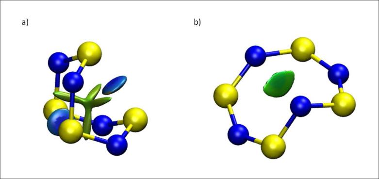
Tetrasulfur tetranitride, S4N4 is a textbook example that illustrates structure, bonding and reactivity in main-group inorganic compounds. Although discovered in 1835, S4N4 remains a subject of intensive study. S4N4 exists as an eight-membered ring. The most stable conformation is a D2d “boat”, in which the ring folds back on itself to give two close S-S contacts bridging the ring.25 Another possible but less-stable conformer is the Cs “cage” structure. Both geometries were found in previous DFT calculations26 and are shown in Fig 6. The greater stability of the boat conformation was explained by the presence of S-S bonding interactions.27 These bonding interactions are clearly revealed by the NCI analysis and are predicted to be fairly strong, on the order of HB strengths, with s(ρ) troughs at ρ ≃ 0.044 au. There is also a non-bonding interaction through the center of the boat. Conversely, there is only a weak van der Waals interaction at the center of the more open cage structure. Thus, the NCI representation explains the greater stability for the boat conformation of S4N4.
FIG. 6.
S4N4 main conformations a) Boat conformation b) Cage conformation. The boat conformation is more stable due to the bridging S-S bond. NCI surfaces correspond to s = 0.4 au and a colour scale of −0.05 < ρ < 0.05 au.
2. Metal complexes: along Hg series
Understanding the solvation of ions and their interactions with ligands is of prime relevance for rationalizing their bioactivity. Since metals play a decisive role in many protein active sites as cofactors, it would then be useful to have simple means of describing metal-ligand interactions.
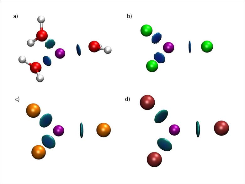
Mercury(II) is a heavy metal cation especially challenging for quantum-mechanical treatment as both correlation and relativistic effects play a crucial role in its bonding and electronic structure. Figures 7a-d show how NCI is used to quickly and efficiently assess Hg complexation sites and discern the strength of binding between Hg2+ and its ligands. The DFT optimized geometry of the [Hg(H2O)3]2+ complex indicates that the three waters bound to Hg are not equivalent, with one of the waters further away than the other (2.2 Å vs. 2.3 Å, see Figure 7a). In order to check the nature of the stabilization we decompose the interaction energy of the complex using the RVS28 (reduced variational space) procedure. Both polarization and charge transfer are significantly weaker for one water molecule than for the other two. While two water molecules show a polarization energy of -15 to -16 kcal/mol and a charge transfer energy of -10 kcal/mol, the third water shows stabilization due to polarization and charge transfer of only -12.7 kcal/mol and -6.2 kcal/mol, respectively. Specific details of the calculation can be found at Supporting Information. The weaker binding of one of the water molecules is clearly revealed by the NCI representation.
FIG. 7.
Complexes of Hg. a)[Hg(H2O)3]2+ b)[Hg(F)3]− c)[Hg(Cl)3]− d)[Hg(Br)3]− . NCI surfaces correspond to s = 0.3 au and a colour scale of −0.1 < ρ < 0.1 au.
NCI is also able to recover the ordering of binding energies when different ligand series are analyzed. Fig 7b-d show [Hg(X)3] complexes (X = F, Cl or Br). F is more strongly bound to Hg than Cl than Br. This result is in agreement with the [Hg(X)3]− binding energies, which are -632.8 (F), -571.0 (Cl) and -562.6 kcal/mol (Br) (see calculation details in Supporting Information).
3. BH3NH3 and the dihydrogen bond
Recently, the term “dihydrogen bond” was coined to describe an interaction of the type D-H···H-E, where D is a typical hydrogen donor (such as N or O). The novelty of this bond is that the acceptor atom is also a hydrogen. Thus, the accepting hydrogen atom must be negatively charged and E is an atom capable of accommodating a hydridic hydrogen. Transition metal and boron atoms are known examples of atoms serving as E atoms.
BH3NH3 is a widely studied example among dihydrogen-bonded complexes.8,35,36 Crab-tree et al,37 placed the NH···HB contacts at the upper end of the energy range for hydrogen bonds. Popelier, instead, assigned these interactions to the range of normal H-bond strengths.35 Morrison and Siddick36 assigned the energies to the lower end of the hydrogen-bond-strength spectrum. The most relevant point made by the later authors is that there is a large conformational difference between the native crystal structure and the gas-phase minima considered by Crabtree et al37 and Popelier.35
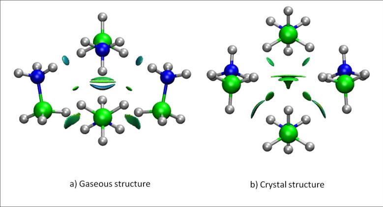
Figure 8 shows the NCI results for two different (BH3NH3)4 complexes. In Figure 8a the structure has been completely optimized, whereas in Figure 8b, the tetramer geometry was derived from the crystalline structure (with the hydrogen positions optimized to ensure correct description of the H-H contacts).38 Calculations were performed using the B3LYP functional and support qualitatively different interaction types in each case. Whereas the gas-phase tetramer gives rise to a highly negative interaction energy, the crystalline structure is not stable with this density functional. This difference suggests that the solid structure is only stabilized by dispersion interactions (which are completely neglected using this functional39); stronger interactions are present in the fully-optimized gas-phase complex.
FIG. 8.
Dihydrogen interactions in a BH3NH3 tetramer in a) the fully-optimized gas-phase geometry and b) the solid-state geometry. NCI surfaces correspond to s = 0.4 au and a colour scale of −0.03 < ρ < 0.03 au.
The NCI description is able to recover the different nature of the interactions in both tetramers, supporting Morrison and Siddick's conclusion.36 Whereas the crystalline tetramer only shows van der Waals contacts, the completely optimized structure gives rise to stronger dihydrogen bonds (with ρ ≃ 0.02 au), which are closer in energy to normal hydrogen bonds.
B. Large systems
1. High affinity host-guest complexes
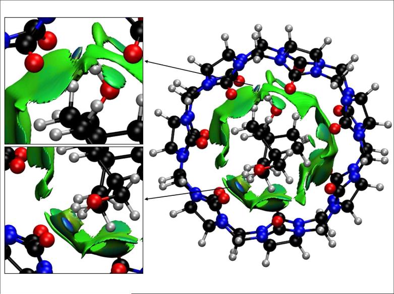
Host-guest complexation, like protein-ligand binding, depends upon a balance of stabilizing and destabilizing non-covalent interactions that contribute to the net thermodynamics. These systems are well known exemplars for understanding non-covalent interactions in more complex biomolecular systems. Recent experimental results show that synthetic host-guest systems can achieve binding affinities that rival those of the tightest-bound protein-ligand complexes. For example, the seven-unit cucurbitural host (CB[7], Figure 9) binds cationic adamantyl29, ferrocene derivatives30, and bicyclo[2,2,2]octane derivatives31–33 with binding constants of 109 to 1013 M−1. Thus, a key test of our NCI method is to understand the magnitude of non-covalent interactions in host-guest complexes.
FIG. 9.
Cucurbit[7]uril-bicyclo[2,2,2]octane derivative inclusion complex. Anchor posts are highlighted in the insets. NCI surfaces show only intermolecular interactions. The gradient cut-off is s = 0.5 au and the colour scale is −0.04 < ρ < 0.04 au.
Mining minima algorithms (M2) have been used to dissect the enthalpic and entropic contributions to high binding affinities.33 Despite the evident electrostatic complementarity of the cationic guests and the electronegative, carbonyl portions of CB[7], electrostatic interactions do not provide a significant net driving force for ligand binding. This is because the strong Coulombic attractions between the guests and CB[7] are off set by the energetic cost of removing solvating water from the cationic guests and the polar hosts upon binding. Instead, two other factors are found to be crucial for stabilizing these complexes. The entropy penalty is unusually small in relation to the enthalpy of binding. This is likely the case because of the rigidity of both the host and the guest structures.31,33 Furthermore, the host and guest molecules studied are complementary in their preferred conformations. These characteristics give rise to favorable enthalpy-entropy compensation that enhances the binding affinities.
NCI analysis allows assessment of host-guest complementarity and the extent to which weak enthalpic interactions stabilize a complex (NCI would not identify stabilization due to purely coulombic forces). Figure 9 shows the binding between a bicyclo[2.2.2]octane derivative and CB[7]. In agreement with M2 results, van der Waals interactions are established throughout the cavity. The binding of the guest is further favored by the two hydroxyl anchors: the hydroxyl substituents on the guest establish strong hydrogen bonds with two carbonyls of the CB7 host (see Fig. 9 insets).
2. Protein-ligand interactions
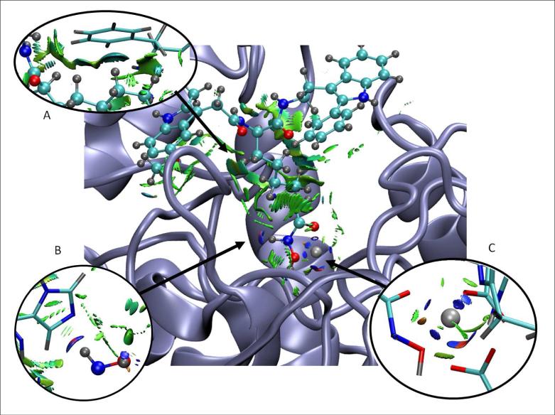
Figure 10 shows the promolecular NCI surface around a V5X ligand in the active site of the HDAC8 protein (obtained from the protein data bank, as 2v5x.pdb, Ref. 34), with the details of the NCI surfaces enlarged. Specific parameters for the Zn2+ contribution to the promolecular density were calculated as described in Section IIIB. The NCI analysis reveals a set of complex interactions between the ligand and the protein, which arise from a combination of specific atom-atom interactions (i.e., hydrogen bonds) as well as broad surfaces indicative of stabilizing vdW interactions. On the lower right hand side of the figure, we show the stabilization of the Zn2+ ion by the protein and ligand. At the lower left, we show the hydrogen bond between the ligand and His140. The top left of the figure shows the vdW surface between the ligand and the Phe139 phenyl ring. NCI analysis clearly highlights how a ligand “fits” the geometry of the active site, and the many small contributions that combine to determine the interaction energy between the ligand and protein.
FIG. 10.
NCI surface around a V5X ligand in the active site of HDAC8 protein. Specific interactions are enlarged in the insets. NCI surfaces show only intermolecular interactions. The gradient cut-off is s = 0.35 au and the colour scale is −0.04 < ρ < 0.02 au.
V. CONCLUSIONS
Algorithms for the analysis of non-covalent interactions based on the NCI index were discussed. An efficient and flexible implementation was established for both SCF and pro-molecular densities, allowing for the analysis of non-covalent interactions in both small molecules and macromolecules. The utility of the method was illustrated with examples from organic and inorganic chemistry. Special emphasis was given to the ability of the new NCI index to provide insight into open issues in bonding.
The NCI code and a manual may be downloaded at: http://www.chem.duke.edu/~yang/software.htm
Supplementary Material
Acknowledgments
This work is supported by the National Science Foundation (CHE-06-16849-03 & CHE-1012357), and the National Institute of Health through the UPCMLD project (P50GM067082) and ROI-GM-061870. J.C.G. thanks the Spanish MALTA-Consolider Ingenio-2010 program under project CSD2007-00045 and E.R.J thanks the Natural Sciences and Engineering Research Council of Canada.
Contributions from H. L. Schmider (wavefunction properties), A. Martín Pendás (parsing routines), E.J. Toone and Y. Wang (CB[7] data), and J. Li (S4N4 data) are greatly acknowledged.
Footnotes
Supporting Information Available: Input files for selected examples and the programming details are available free of charge via the Internet at http://pubs.acs.org.
References
- 1.a Chandler D. Nature. 2005;437:640. doi: 10.1038/nature04162. [DOI] [PubMed] [Google Scholar]; b Panigrahi SK, Desiraju GR. Proteins: Struct., Funct., Bioinf. 2007;67:128. doi: 10.1002/prot.21253. [DOI] [PubMed] [Google Scholar]
- 2.a Fenniri H, Packiarajan M, Vidale KL, Sherman DM, Hallenga K, Wood KV, Stowell JG. J. Am. Chem. Soc. 2001;123:3854. doi: 10.1021/ja005886l. [DOI] [PubMed] [Google Scholar]; b Kruse P, Johnson ER, DiLabio GA, Wolkow RA. Nano Lett. 2002;2:807. [Google Scholar]
- 3.a Fiedler S, Broecker J, Keller S. Cell. Mol. Life Sci. 2010;67:1779. doi: 10.1007/s00018-010-0259-0. [DOI] [PMC free article] [PubMed] [Google Scholar]; b Dill KA. Biochemistry. 1990;29:7133. doi: 10.1021/bi00483a001. [DOI] [PubMed] [Google Scholar]
- 4.Silvi B. Phys. Rev. Lett. 1994;73:842. doi: 10.1103/PhysRevLett.73.842. [DOI] [PubMed] [Google Scholar]
- 5.Bickelhaupt FM, Baerends E. Angew. Chem. Int. Ed. 2003;42:4183. doi: 10.1002/anie.200350947. [DOI] [PubMed] [Google Scholar]
- 6.Weinhold F. Angew. Chem. Int. Ed. 2003;42:4188. [Google Scholar]
- 7.Cioslowski J, Mixon ST. Can. J. Chem. 1992;70:443. [Google Scholar]
- 8.Matta CF, Hernández-Trujillo J, Tang T, Bader RFW. Chem. Eur. J. 2003;9:1940. doi: 10.1002/chem.200204626. [DOI] [PubMed] [Google Scholar]
- 9.Klein RA. Chem. Phys. Lett. 2006;425:128–133. [Google Scholar]
- 10.Bader RFW. Atoms in Molecules: A Quantum Theory. Oxford University Press; Oxford (UK): 1990. [Google Scholar]
- 11.Espinosa E, Souhassou M, Lachekar H, Lecomte C. Acta Cryst B. 1999;55:563. doi: 10.1107/s0108768199002128. [DOI] [PubMed] [Google Scholar]
- 12.Grabowski SJ. J. Phys. Chem. A. 2001;105:10739. [Google Scholar]
- 13.Becke AD, Edgecombe KE. J. Chem. Phys. 1990;92:5397. [Google Scholar]
- 14.Silvi B, Savin A. Nature. 1994;371:683. [Google Scholar]
- 15.Contreras-García J, Recio JM. Theor. Chem. Acc. DOI: 10.1007/s00214-010-0828-1. [Google Scholar]
- 16.Alikhani ME, Fuster F, Silvi B. Struct. Chem. 2005;16:203. [Google Scholar]
- 17.Johnson ER, Keinan S, Mori-Sánchez P, Contreras-García J, Cohen AJ, Yang W. J. Am Chem. Soc. 2010;132:6498. doi: 10.1021/ja100936w. [DOI] [PMC free article] [PubMed] [Google Scholar]
- 18.Bohórquez HJ, Boyd RJ. Theor. Chem. Acc. 2010;127:393. [Google Scholar]
- 19.Arfken G. Mathematical Methods for Physicists. Academic Press; Orlando: 1985. [Google Scholar]
- 20.Bader RFW, Essén H. J. Chem. Phys. 1984;80:1943–1960. [Google Scholar]
- 21.Noury S, Krokidis X, Fuster F, Silvi B. Comput. Chem. 1999;23:597. [Google Scholar]
- 22.Spackman MA, Maslen EN. J. Phys. Chem. 1986;90:2020–2027. [Google Scholar]
- 23.Pendás AM, Luaña V, Pueyo L, Francisco E, Mori-Sánchez P. J. Chem. Phys. 2002;117:1017–1023. [Google Scholar]
- 24.Perdew JP, Wang Y. Phys. Rev. B. 1992;45:13244–13249. doi: 10.1103/physrevb.45.13244. [DOI] [PubMed] [Google Scholar]
- 25.DeLucia ML, Coppens P. Inorg. Chem. 1978;17:2336–2338. [Google Scholar]
- 26.Pritchine EA, Gritsan NP, Zibarev AV, Bally T. Inorg. Chem. 2009;48:4075–4082. doi: 10.1021/ic802145x. [DOI] [PubMed] [Google Scholar]
- 27.Gleiter R. J. Chem. Soc. A. 1970:3174–3179. [Google Scholar]; Salahub DR, Messmer RP. J. Chem. Phys. 1976;64:2039–2047. [Google Scholar]
- 28.Stevens WJ, Fink WH. Chem. Phys. Lett. 1987;139:15–22. [Google Scholar]
- 29.Liu S, Rupic C, Mukhpadhayay P, Chakrabarti S, Zavalij PY, Isaacs L. J. Am. Chem. Soc. 2005;127:1595–15967. [Google Scholar]
- 30.Jeon WS, Moon K, Park SH, Chun H, Ko YH, Lee JY, Samal S, Selvapalam N, Rekharsky MV, Sindelar V, Sobransingh D, Inoue Y, Kaifer AE, Kim K. J. Am. Chem. Soc. 2005;127:12984. doi: 10.1021/ja052912c. [DOI] [PubMed] [Google Scholar]
- 31.Rekharsky MV, Mori T, Yang C, Ko YH, Selvapalam N, Kim H, Sobransingh D, Kaifer AE, Liu S, Isaacs L, Chen W, Moghaddam S, K. Gilson MK, Kim K, Inoue Y. Proc. Natl. Acad. Sci. U. S. A. 2007;104:20737. doi: 10.1073/pnas.0706407105. [DOI] [PMC free article] [PubMed] [Google Scholar]
- 32.Liu S, Ruspic C, Mukhopadhyay P, Chakrabarti S, Zavalij PY, Isaacs L. J. Am Chem. Soc. 2005;127:15959–15967. doi: 10.1021/ja055013x. [DOI] [PubMed] [Google Scholar]
- 33.Moghaddam S, Inoue S, Gilson MK. J. Am. Chem. Soc. J. Am. Chem. Soc. 2009;131:4012–4021. doi: 10.1021/ja808175m. [DOI] [PMC free article] [PubMed] [Google Scholar]
- 34.Vannini A, Volpari C, Gallinari P, Jones P, Mattu M, Carfi A, Defrancesco R, Steinkuhler C, Di Marco S. Embo Rep. 2007;8:879. doi: 10.1038/sj.embor.7401047. [DOI] [PMC free article] [PubMed] [Google Scholar]
- 35.Popelier PLA. J. Phys. Chem. A. 1998;102:1873–1878. [Google Scholar]
- 36.Morrison CA, Siddick MM. Angew. Chem. Int. Ed. Engl. 2004;116:4884–4886. [Google Scholar]
- 37.Richardson TB, de Gala S, Crabtree RH, Siegbahn PEM. J. Am. Chem. Soc. 1995;117:12875. [Google Scholar]
- 38.Klooster WT, Koetzle TF, Siegbahn PEM, Richardson TB, Crabtree RH. J. Am. Chem. Soc. 1999;121:6337. [Google Scholar]
- 39.Johnson ER, Wolkow RA, DiLabio GA. Chem. Phys. Lett. 2004;394:334–338. [Google Scholar]
Associated Data
This section collects any data citations, data availability statements, or supplementary materials included in this article.


