Abstract
PURPOSE
To develop a system for artifact suppression in electrocardiogram (ECG) recordings obtained during interventional real-time magnetic resonance imaging.
MATERIALS AND METHODS
We characterized ECG artifacts due to radiofrequency pulses and gradient switching during MRI in terms of frequency content. A combination of analog filters and digital least mean squares adaptive filters were used to filter the ECG during in vivo experiments and the results were compared with those obtained with simple low-pass filtering. The system performance was evaluated in terms of artifact suppression and ability to identify arrhythmias during real-time MRI.
RESULTS
Analog filters were able to suppress artifacts from high-frequency radiofrequency pulses and gradient switching. Remaining pulse artifacts caused by intermittent preparation sequences or spoiler gradients required adaptive filtering because their bandwidth overlapped with that of the ECG. Using analog and adaptive filtering, a mean improvement of 38dB (n=11, peak QRS signal to pulse artifact noise) was achieved. This filtering system was successful in removing pulse artifacts which obscured arrhythmias such as premature ventricular complexes and complete atrioventricular block.
CONCLUSION
We have developed an online ECG monitoring system employing digital adaptive filters which enables the identification of cardiac arrhythmias during real-time MRI-guided interventions.
Keywords: electrocardiogram, MRI, gradient artifacts, adaptive filter
INTRODUCTION
MRI guided cardiovascular interventional procedures are being developed to reduce X-ray exposure or to allow novel procedures that exploit the soft tissue imaging capability of MRI (1). Catheterization can induce lethal arrhythmia, so continuous instantaneous electrocardiography (ECG) and hemodynamic monitoring is mandatory. MRI induces electromagnetic perturbations that interfere with conventional ECG recordings (2) and remains a significant barrier to clinical interventional cardiovascular MRI. Patients undergoing catheterization procedures require continuous hemodynamic monitoring, and ECG is studied closely for evidence of arrhythmia. Since electrophysiological signals are known to suffer from severe electromagnetic interference from the MR scanner (3,4), ECG distortion can result in overlooked or misinterpreted cardiac events that put the patient at risk.
MR-induced ECG artifacts are attributed to three primary sources of interference. First, by placing the patient inside the MRI bore, the static magnetic field (B0) can induce magnetohydrodynamic voltages in the ECG. When conductive fluid such as blood travels across the strong magnetic field, an electric field is formed and introduces a voltage signal that manifests itself onto the ECG ST segment (5). Second, during MRI radiofrequency (RF) pulses that oscillate at the Larmor frequency (64MHz at 1.5T) inductively couple to any conductive material inside the MRI suite, thereby distorting electrophysiological signals (6,7). The intensity and frequency of RF artifacts are dictated by the imaging sequence. Real-time sequences used during interventional MRI usually employ short repetition times and high flip angles which create a hostile RF environment for monitoring equipment inside the MRI suite. Additionally, RF waves are far-reaching and may couple to the patient, cables, and circuits (8,9). Fortunately, the bandwidth of RF signals is far beyond the clinically-relevant bandwidth of the ECG (0.05–100 Hz) and can therefore be efficiently eliminated by proper hardware shielding, fiber optic transmission lines, and simple low pass filters (3,10). ECG is further corrupted by the time-varying MR gradients (8,10,11). The spectral characteristics of gradient artifacts may contain frequencies from 10–5000 Hz. In the case of multi-slice real-time MRI, gradient pulses responsible for slice, frequency, and phase encoding switch at a much higher rate than spoiler (crusher) gradients, which occur only when the transverse magnetization needs to be dephased after each slice acquisition. The low frequency components often overlap with the ECG bandwidth, making artifact removal challenging. Studies have reported how gradient artifacts can be minimized by keeping electrodes close together and near the magnet isocenter while preventing the formation of loops (12). However, such passive methods are able to reduce ECG artifacts only to a limited degree, and there is a need for more sophisticated approaches to produce a clinically useful ECG during MRI.
Several methods have been investigated to suppress MR artifacts, including the use of wavelets (13) and independent component analysis (14) that are not appropriate for real-time processing. Moreover, fixed low pass filters with low cutoff frequencies have been used, but they have several limitations (10). These include the undesirable distortion of ECG information and the inability to adapt to different scanning parameters due to fixed filter coefficients. For real-time MRI where slice orientations and other imaging parameters may vary continuously and unpredictably, fixed filters are insufficient. This paper will focus on signal processing techniques based on adaptive noise cancellation, which has been proposed by several groups to remove MR gradient artifacts from both ECG’s (8,9,15,16) and electroencephalograms (17,18). Adaptive noise cancellation has the advantage of finding the best filter properties to remove artifacts that have overlapping spectra with the desired signal. Real-time adaptive noise cancellation is implemented using the least mean squares (LMS) adaptive filtering algorithm because of low computation cost (19). To date, the algorithm’s compatibility with modern MRI real-time sequences and its ability to resolve arrhythmias during procedures has yet to be examined. In this work, we review the sources of electromagnetic interference on ECG recording during MRI and evaluate the performance of adaptive noise cancellation during real-time MRI scanning in vivo.
MATERIALS AND METHODS
System Modeling
During MRI, corrupted ECG signals can be represented as a linear combination of the true ECG signal plus the three main sources of noise described above: s(t) = secg(t) + nRF(t) + nMHD(t) + nGA(t), where secg(t) is the clean ECG waveform; nRF(t) represents the RF artifact; nMHD(t) is the artifact from the magnetohydrodynamic effect; and nGA(t) is the MR gradient-induced artifact.
This study will focus on gradient induced artifacts, nGA(t), which are the predominant artifacts that need to be suppressed. The magnetohydrodynamic effect does not pose, in most patients, significant problems in a 1.5T scanner for the purpose of R-wave detection. Additionally, these artifacts may be reduced passively by placing the differential electrodes close together (20), although this also reduces the absolute voltage seen at the electrodes, so that the system may become more sensitive to induced voltages from other noise sources. The frequency of RF pulses used in MRI (64MHz at 1.5T) is orders of magnitude higher than the ECG frequency components, and the related artifacts may be eliminated with analog low pass filters and fiber optic transmission lines (3,21).
According to Faraday’s Law of Induction, the n(GA)(t) term represents the voltage induced in a conductive loop as the result of the time-varying magnetic gradients. The conductive loops may be formed by the subject’s body, electrodes, and ECG leads, which are all placed in close proximity to the gradient coils. This law is represented by the following equations (8):
| [1] |
| [2] |
where φ is the magnetic flux, dS is the active surface area of the conductive loop, and B is the magnetic field in the loop. The magnetic field can be written in terms of the time-varying gradient field, G(t) and position vector r of the conductive loop as shown in Eq. [2]. For simplicity, we neglect the effects of concomitant fields (22) and assume that G(t) is comprised of the gradients explicitly played on each of the physical axes. Note that the conductive loop surface area, dS, is determined by the electrode placement on the subject’s body and the resulting current paths. The orientation of the electrodes with respect to the fluctuating fields will affect the magnitude of the induced artifacts, as shown by the term inside the integral in Eq. [1]. As shown in Eq. [2], the gradient magnitude and resulting field increases with distance from the magnet isocenter, which will cause increases in the magnitude of the induced artifacts.
In the discrete time domain, assuming that the system is linear and time-invariant (10), the gradient-induced artifact A[n] = ⌊Ax[n],Ay[n],Az[n]⌋ can be modeled as the convolution of the axis-dependent impulse response functions h[n] = ⌊hx[n],hy[n],hz[n]⌋ and the gradient signals G[n] = ⌊Gx[n],Gy[n],Gz[n]⌋ (8,10):
| [3] |
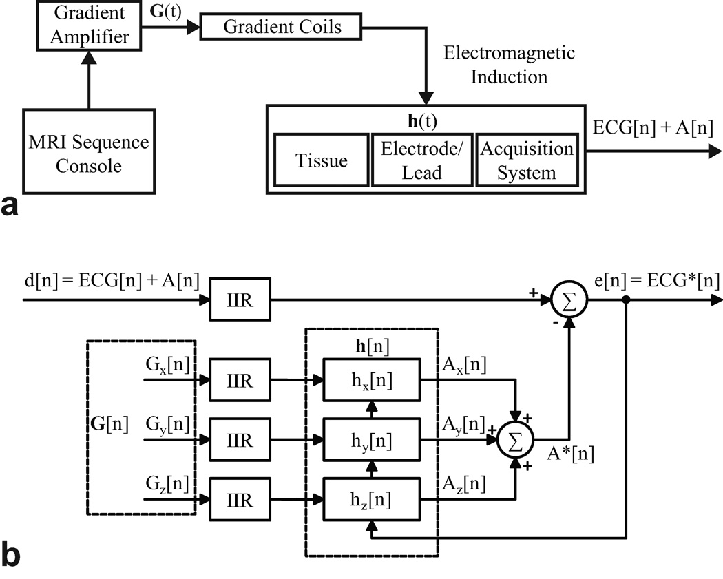
This model is illustrated in Fig. 1a. In practice, it is difficult to determine h[n] directly by deconvolution (23). Furthermore, the impulse response may change over time due to respiratory and other patient movement. Due to the time-varying nature of the impulse response (8,10), an adaptive technique, which does not require a priori knowledge of the signal or noise characteristics, is well suited for noise cancellation.
Figure 1.
a: Linear shift invariant modeling of Faraday induction by MRI gradient switching. b: Architecture of least mean squares adaptive filtering.
Adaptive Filter
As illustrated in Fig. 1b, adaptive filtering operates on the three reference gradient signals obtained from the MR scanner to produce the estimated gradient-induced artifacts from each axis, which are summed together (A*[n]). For noise estimation, the reference signals should be well-correlated in time with the noise, but not with the signal of interest (ECG) (8,15). The estimated artifacts are subtracted from the primary noisy signal, d[n] = ECG + A[n]. The difference is the error signal, e[n], which is used to adjust the coefficients of the impulse responses such that the error signal converges to a minimum after a number of iterations. Note that e[n] eventually yields the filtered, denoised signal, ECG*.
Least Mean Squares
The least mean squares (LMS) algorithm is chosen as the strategy to minimize the error signal (19). Each artifact channel, Ai[n], is modeled as the convolution of the gradient signal, Gi[n] with a finite impulse response (FIR) filter, hi[n], as shown in Eq. [4]. The error signal, ei[n], is computed from the primary noisy signal by equation Eq. [5]. The error is then used in equation Eq. [6], which is the optimization technique that minimizes the mean square error (MSE) by adjusting the next set of FIR filter coefficients hi[n + 1]. This algorithm is performed on an ongoing basis during ECG artifact correction.
| [4] |
| [5] |
| [6] |
The FIR filter length, L, should be large enough to adequately model the system and is usually determined empirically (15). It is also important to note that the larger the filter length, the greater the computational time. In Eq. 6, µ is the step size factor that determines how fast the system converges to produce the minimum MSE. A step size too large may cause instability, while a small value will take more time to converge. To ensure stability, the step size should comply with the following constraint (19):
| [7] |
where Px is the power of the input signal d[n].
Data Acquisition System
In heart rate analysis, QRS power mostly lies in the 3–17 Hz band (24) and ECG sensors for this purpose commonly have a narrow bandwidth (0.5–20 Hz) to sufficiently suppress gradient artifacts (3,14) and reduce baseline drift due to respiration. However, patient monitoring requires a slightly wider bandwidth (0.5–40 Hz), while diagnostic quality ECG needs to operate in the 0.05–100Hz range to detect subtler changes in the waveforms (25). In this study, ECG sensors with −3dB corner frequencies at 0.5Hz and 50Hz and gain of 1000 were constructed based on instrumentation schematics and application notes from the integrated circuit manufacturer (Analog Devices, Norwood, MA).
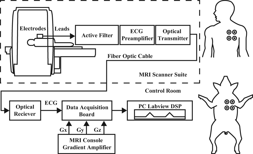
The data acquisition chain and electrode placements are illustrated in Fig. 2. ECG limb lead signals were acquired by connecting MRI-compatible electrodes and short, high resistive leads (InVivo Corporation, Orlando, FL) to an optical sensor placed at the end of the MRI scanner table. Unity-gain voltage followers were installed in the first stage of the sensor for impedance conversion. The sensor features an integrator, a 4-pole analog band-pass filter, an instrumentation amplifier, and an optical transmitter that includes a modulation circuit to bias the LED into its linear range. Fiber glass cables (Industrial Fiber Optics, Tempe, AZ) carried ECG signals out of the MRI suite to an optical receiver that converted the signal back to voltage. Signals were digitized with a sampling rate of 10,000 Hz by a data acquisition board (PXI-6225, National Instruments, Austin, TX) and digitally processed on a PC running LabVIEW (National Instruments, Austin, TX). Offline signal to noise analysis was performed with MATLAB (MathWorks, Natick, MA).
Figure 2.
Left: Diagram of ECG instrumentation and acquisition setup. Right: Subject electrode placements.
Signals were digitally pre-processed before adaptive filtering (Fig. 1b). For fast gradient-switching real-time MRI sequences, most of the high frequency artifact energy was removed by low pass filtering. Thereafter, infinite impulse response (IIR) low pass filters were applied to primary and reference signals. Residual RF artifacts in ECG were also suppressed after this process. Additionally, DC offsets, which degrade the performance of adaptive filters (26), were removed by digital IIR high pass filters.
Real-time MRI
Experiments were performed on a clinical 1.5T MRI scanner (Espree, Siemens Medical Solutions, Erlangen, Germany). The real-time MR imaging system was developed by our lab for use in an interventional setting (27), and features an interactive volume rendered display of multiple 2D slices. Real-time steady-state free-precession (SSFP) sequences were used with the following typical parameters: TR/TE = 3.23/ 1.62 ms, flip angle = 45, slice thickness = 6.0 mm, FOV = 340 × 255 mm, matrix = 108 × 192, bandwidth = 789 Hz/pixel. Gradient echo sequences (TR/ TE = 14/10 ms or 100/10 ms, flip angle = 15, slice thickness = 3 mm, FOV = 200 × 200 mm, matrix = 128 × 128, bandwidth = 2600 Hz/pixel) were also used to test adaptive noise cancellation performance.
Signal to Noise Ratio Analysis
To evaluate the performance of the adaptive noise cancellation system, the SNR was defined by:
| [8] |
where, within each 5 second recording window, QRS is the maximum peak-to-peak voltage of the QRS complex, and PA represents the maximum pulse artifact peak-to-peak voltage. Scanner gradient signals were used to locate the corresponding pulse artifacts.
For each subject, the SNR of 5 windows were averaged. SNR values were computed for real-time SSFP with three orthogonal slices with spoiler gradients played sequentially on all three gradient axes.
In Vivo Experiments
Animal protocols were approved by the Institutional Animal Care and Use Committee. Pigs underwent ketamine and/or telezol/xylazine induction followed by endotracheal intubation, mechanical ventilation, and received 1–2% isoflurane. Simultaneous ECG acquisition and MR imaging were performed on 10 pigs (42 ± 10 kg). Experiments designed to investigate filter performance in the presence of arrhythmias were performed on two animals. For one animal a pig-tail catheter was manipulated inside the right ventricle. The second received 30 mg boluses of intravenous adenosine. Both experiments were carried out under real-time MRI and ECG monitoring. The human volunteer experiment was conducted with written informed consent and approval by our Institutional Review Board. For all in vivo experiments four limb electrodes (right arm, left arm, right leg, left leg) were placed on the chest to acquire two ECG leads (see Fig 2).
RESULTS
Real-time MRI Artifact Analysis
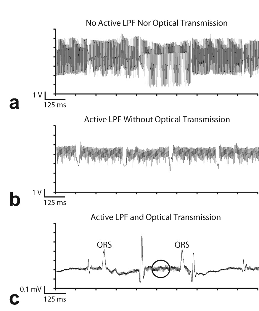
Figure 3 shows examples of RF and gradient interference induced by multi-slice real-time SSFP imaging in vivo and the results of using filter and optical hardware to minimize them. The pig’s neck was positioned at the magnet isocenter in order to magnify the effect of gradient switching. No digital pre-processing was applied to these signals. The trace in Fig. 3a was recorded in absence of the 4-pole active low pass filter and optical system. Instead, a 1-pole RC filter was used along with a coaxial cable that carried the signal out of the MRI suite and into the acquisition board. It can be observed that the ECG is heavily contaminated by a combination of RF and gradient noise. The gradient switching pattern is clearly visible, which includes sections of high frequency interferences with intermittent “gaps.” These gaps reflect the intermittent spoiler gradients employed in multi-slice SSFP imaging.
Figure 3.
Example of ECG artifacts during real-time SSFP. a: Results from acquisition using coaxial cable transmission lines without 4-pole analog low pass filter in the ECG sensor. b: 4-pole analog low pass filters partially suppress MRI ECG artifacts. Coaxial cables are still vulnerable to RF induction. c: ECG SNR improved with optical system and analog filter. Some residual RF artifact remains (circle).
The benefit of adding a 4-pole active low pass filter to the ECG sensor is shown in Fig. 3b. The reduction in overall noise amplitude is achieved by suppressing gradient and RF artifacts picked up by the patient and ECG leads. However, the acquisition system is still vulnerable to RF interference downstream of the filter. Despite shielding, the RF induces voltage along the long coaxial cable as the signal is carried out of the MRI suite. This provides the impetus to replace the electrical coaxial cable with a glass fiber line that is immune to EM interference. The result of using a fiber optic system is shown in Fig. 3c. The high frequency RF and gradient switching artifacts are greatly reduced in comparison to the trace in Fig. 3a, though some high frequency artifacts remain, as denoted by the circled region. Pulse artifacts caused by the intermittent spoiler gradients remain because their frequency content overlaps with the ECG spectrum and is below the corner frequency of the low pass filter. Imaging sequences with long TR settings will also have the same undesirable effect. These pulse artifacts can be easily misinterpreted as spurious QRS complexes and will obscure arrhythmia detection during MRI.
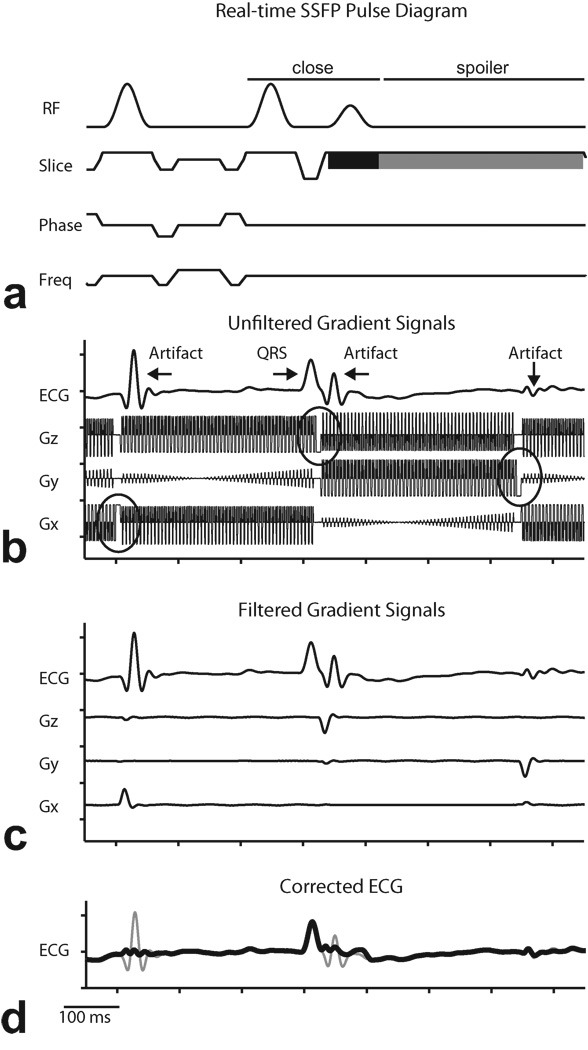
The pulse sequence diagram for the multi-slice real-time SSFP sequence is shown in Fig. 4a. Following the last readout of a slice, there is a closing sequence to store the magnetization, followed by a spoiler gradient on the slice axis(28). As seen in Fig. 4b, residual high frequency MR artifacts in Fig. 3c are suppressed by digital pre-processing with low-pass IIR filters, but the pulse artifacts caused by the spoiler gradients are still visible. The gradient reference signals (Gz, Gy, and Gx) in Fig. 4a were acquired from the MR scanner gradient amplifiers simultaneously before filtering. Note that the IIR filters introduce phase delays on the ECG signal so that the pulse artifacts slightly lag the spoiler gradients, by approximately 7 ms. Because adaptive filtering requires the reference signals to be correlated in time with the noise (pulse artifacts), the three gradient signals are pre-processed by the same filter systems used for the ECG channel. The results are shown in Fig. 4c. Note that the gradient signals now resemble the ECG pulse artifacts and are suitable for the LMS filter. The final filtered ECG signal is shown in Fig. 4d.
Figure 4.
Demonstration of digital preprocessing of reference signals in least mean squares adaptive filtering. a: Pulse sequence diagram for multi-slice real-time SSFP showing closing sequence to store magnetization (“close”), combined slice select (black) and spoiler (gray) on slice gradient. b: Example of low-pass filtered contaminated ECG recorded simultaneously with gradient signals acquired from scanner during multi-slice real-time SSFP imaging. Circles denote spoiler gradients. c: Magnified plot showing relationship between spoiler gradients and ECG pulse artifacts. d: Corrected ECG (thick line) overlaid on ECG signal before adaptive filtering (thin line).
From Eq. 1, each gradient axis contributes independently to B. Furthermore, each ECG lead has a unique position with respect to the magnet isocenter (r in Eq. 2). Therefore, a unique set of filter coefficients must be computed for each gradient axis for each ECG lead.
ECG Artifact Cancellation
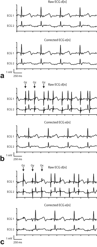
Online adaptive noise cancellation was implemented during real-time SSFP imaging in vivo. For all experiments, the LMS algorithm used an FIR filter of length 348 and a step size of 1E-5. These parameters were chosen empirically to provide good pulse artifact suppression. To demonstrate the dependence of ECG gradient artifacts on MR pulse sequence parameters, three types of real-time imaging sequences were tested: single slice imaging, single slice imaging with fat suppression, and multi-slice imaging. Both the single slice imaging with fat suppression and multi-slice imaging sequences employ spoilers between slice acquisitions. Examples of the effects of these three real-time imaging modes are depicted in Fig. 5, along with the results of adaptive filtering after the error signals have converged to steady state. ECG signals were acquired in vivo using typical real-time SSFP parameters.
Figure 5.
Representative two channel ECG recordings and adaptive filtering results during real-time SSFP (Subject 1). “Raw ECG” signal includes analog low-pass filtering but not adaptive filtering, and “Corrected ECG” signal includes analog and adaptive filtering. Arrows indicate the gradient axis responsible for the spoiler gradient artifact. a: One slice (no spoilers). Gradient artifacts were suppressed sufficiently by low-pass filtering, and adaptive filter did not introduce any additional artifacts. b: One slice with fat saturation. Large Gz gradient artifacts (which occur once per slice, or every ~350 ms)are evident in low-pass filtered signal but are suppressed by adaptive filter. c: Three slices. Gradient artifacts appear on each axis, once per slice. Largest amplitude artifacts are from Gz, but artifacts from Gx and Gy are also evident in Raw ECG signal. Artifacts from all three axes are adequately suppressed by adaptive filter.
Figure 5 shows ECG data from subject 1 (see Table 1). “Raw ECG” refers to the ECG signal after IIR filtering before adaptive filtering. The “Corrected ECG” signal includes adaptive filtering. During single slice imaging the gradient artifacts were adequately suppressed by low pass filters alone, as shown in Fig. 5a. This particular sequence does not employ spoiler gradients, thus most of the energy from induced artifacts is in the high frequency band. The reference signals (filtered gradients), which correlate with the high frequency noise, were also filtered to zero after digital pre-processing. According to Eq. 4, a zero-valued reference signal will leave the error signal (denoised ECG) unaltered after adaptive filtering. This example confirms that without the presence of low frequency artifacts, the algorithm does not distort the ECG signal.
Table 1.
Signal to Noise Evaluation of Pulse Artifact Suppression in Multislice Real-time SSFP
| SNR (dB) | ||||
|---|---|---|---|---|
| Subject | Raw ECG | Corrected ECG | 20 Hz Filter | |
| Pig | 1 | −3.5 | 31.3 | 4.8 |
| Pig | 2 | −1.4 | 34.2 | 19.0 |
| Pig | 3 | −1.8 | 40.4 | 6.6 |
| Pig | 4 | 14.3 | 42.3 | 21.3 |
| Pig | 5 | 5.7 | 34.2 | 21.2 |
| Pig | 6 | −8.2 | 41.2 | 13.3 |
| Pig | 7 | −13.5 | 30.6 | 5.3 |
| Pig | 8 | −6.7 | 32.0 | 10.5 |
| Pig | 9 | 1.0 | 39.0 | 19.6 |
| Pig | 10 | −8.9 | 26.5 | 9.6 |
| Human | 11 | −10.5 | 30.4 | 13.1 |
| Mean ± SD | −3.0 ± 8.0 | 34.7 ± 5.2 | 13.1 ± 6.3 | |
Figure 5b shows the effect of fat suppression pulses in single slice imaging, which uses spoiler gradients to dephase the transverse component of fat in MR images (29). Pulse artifacts were clearly observed in the raw signals because their spectral energy overlaps with that of the ECG. Moreover, for each ECG lead, pulse artifacts were similar in shape and amplitude since spoiler gradients were applied exclusively on one axis (Gz) for transverse slices. However, when comparing one lead to another, the artifacts no longer shared the same characteristics due to the spatial-dependence of the field due to gradient switching. After adaptive filtering, signals exhibited great improvement in pulse artifact suppression. The improved SNR enabled better identification of the QRS complexes for monitoring.
Table 1 summarizes the SNR analysis of ECG recorded during 3-slice real-time SSFP. Comparisons were done between the proposed adaptive filtering technique and a conventional 20Hz 4-pole digital low pass filter. For the digital low pass filter analysis, a 20 Hz corner frequency was selected because the filter design is used by many clinical MRI ECG sensors to limit gradient artifacts (3,11,14). Although the narrow bandwidth may be acceptable for QRS detection, SNR will not improve remarkably because it attenuates the energy of the desired signal as well as the noise. This compromises the accurate representation of ECG morphology. Based on the results of 10 pig subjects (subjects 1–10) and 1 healthy human volunteer (subject 11), the average raw ECG signal had an SNR of −3 dB. In some cases, the pulse artifacts had amplitudes greater than the QRS. Adaptive filtering improved the average SNR of all the subjects to approximately 35 dB. In addition, SNR improvement by adaptive filtering was consistently superior to the 20 Hz filter, which on average only increased the SNR to 13 dB.
ECG recordings during 3-slice (transverse, sagittal, coronal) imaging are displayed in Fig. 5c. In multi-slice sequences, spoiler gradients on each slice-selective axis created a different pulse artifact. Again, adaptive filtering achieved a significant reduction in pulse artifacts without affecting the desired signal.
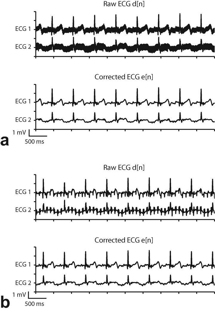
To demonstrate the applicability of adaptive filtering in other cardiac imaging protocols, we also tested it with GRE sequences, as shown in Fig. 6. In general, the frequency characteristics of GRE are lower than that of real-time SSFP. GRE with long (100ms) and short (14 ms) TR’s produced observable gradient artifacts due to their spectral overlap with the ECG band. The pulse artifacts were suppressed effectively with the proposed technique.
Figure 6.
Adaptive filter results during GRE (Subject 1). a: TR= 14 ms. b: TR = 100 ms. “Raw ECG” signal includes analog low-pass filtering but not adaptive filtering, and “Corrected ECG” signal includes analog and adaptive filtering. Gradient switching artifacts are evident in the Raw ECG signal and are not eliminated by the analog low-pass filter, but are significantly suppressed by adaptive filtering.
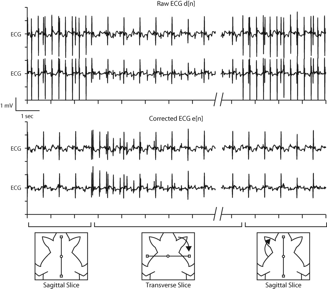
Figure 7 shows the ECG of subject 3 with the filter coefficients adapting to changes in slice orientation. Beginning with a sagittal slice, the first half of the trace shows the raw ECG contaminated with pulse artifacts induced by Gx spoiler gradients and the corrected ECG, after the adaptive filter converged. Note that the filter coefficients for the other two gradient axes were still zero at this point. Upon changing the slice orientation to transverse, spoiler gradients on the Gz axis introduced a different ECG artifact profile that was eventually suppressed by updating the Gz filter coefficients. In this example, the convergence time was approximately 4 seconds with a step size of 0.0002. Larger step sizes produced faster convergence times, but the SNR of the converged waveforms became degraded. Finally, when the slice was returned to the sagittal position, the existing Gx filter coefficients were able to adequately suppress the artifacts without further update. This demonstrates that once the filter coefficients are established for a gradient axis, they appropriately model the system response and do not need to be recalculated unless the electrode position with respect to the magnet isocenter changes significantly (e.g. repositioning of the electrodes or movement of the magnet table). In practice, the electrodes move some with patient respiration, and some minor updating of the filter coefficients is necessary, but this occurs relatively quickly, as can be seen when the slice reverts to the sagittal orientation in Fig. 7.
Figure 7.
Example of least mean squares coefficients update during interactive real-time MRI. Upon changing slice orientation from sagittal to transverse, the resulting change in pulse artifacts causes update of filter coefficients (from an initialized zero value). After approximately 4 seconds, denoised ECG reaches steady state and adapts to the new sequence settings. When the slice returns to sagittal orientation, the filter coefficients require little or no updating, and the ECG remains clean.
Arrhythmia Detection during MRI
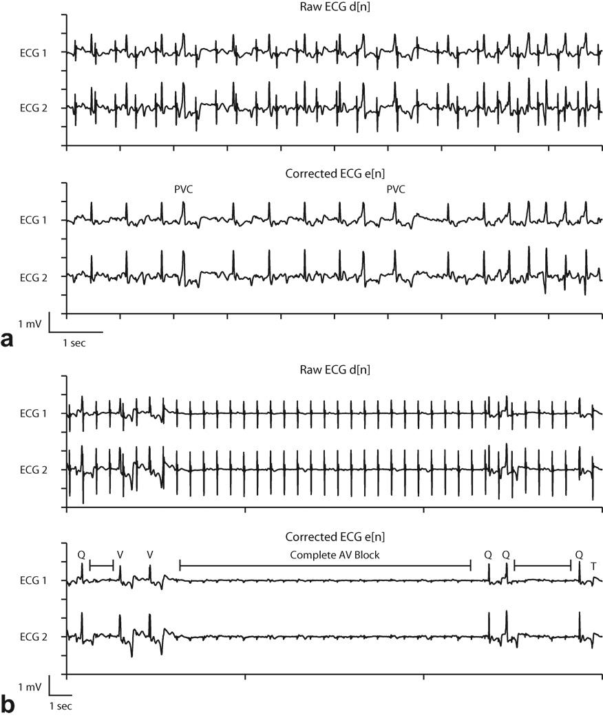
Adaptive noise cancellation was used during two animal cardiac catheterization studies (subjects 2, 8 in Table 1) under multi-slice real-time SSFP imaging to evaluate performance in arrhythmia monitoring. In subject 8, a pigtail catheter was manipulated in the right and left ventricles to induce premature ventricular contractions, shown in Fig. 8a. Premature ventricular contractions are characterized by a premature occurrence of a widened complex typically followed by a compensatory pause before the next complex. Without adaptive filtering, the signal was corrupted by periodic pulse artifacts that resembled normal QRS complexes and obstructed the identification of the arrythmia.
Figure 8.
Adaptive filter results during arrhythmia induction. Identification of premature ventricular contractions (PVC) (a) and transient complete atrioventricular (AV) block (b) was enhanced in the corrected ECG waveforms. In (b), Q=normal QRS, V=ventricular escape beat, T=T wave, and |-|= interval of complete atrioventricular block. See text for details.
Subject 2 received intravenous administration of adenosine, which created transient complete atrioventricular (AV) block. Before adaptive filtering, the pulse artifacts resembled normal QRS complexes (Fig 8b, top). After adaptive filtering, intervals of complete AV block were evident, characterized by the absence of QRS complexes and standalone P waves (marked intervals in Fig 8b, bottom). With adaptive filtering it was also possible to distinguish between normal appearing QRS complexes (Q) and ventricular escape beats (V). At the end of the recorded waveform a T wave (T), which was obscured by a pulse artifact in the raw ECG, is easily identified in the corrected ECG.
DISCUSSION
During conventional and real-time MRI, the ECG is often rendered unreliable by electromagnetically induced artifacts. By identifying and addressing the hardware and signal processing challenges, we demonstrated the feasibility of continuous ECG monitoring and arrhythmia identification during real-time MRI.
Adaptive techniques have been studied by other groups to suppress ECG gradient artifacts. The Wiener (23), and Recursive RLS (15) algorithms yielded promising results, but were implemented off-line. A post-processing method using the fast Fourier transform to calculate the gradient signal’s impulse response has also been proposed (10). Finally, the LMS algorithm was previously implemented online with standard non real-time MRI sequences (8,9). This paper builds on these previous studies with a focus on online artifact suppression pertaining to interactive real-time cardiac imaging. Furthermore, we report that adaptive filtering was effective in a clinical setting in restoring arrhythmic waveforms that would otherwise have been misinterpreted. Our system may also have applications in improving R-wave detection for conventional triggered or gated exams, and may be integrated with other systems designed for this purpose (30).
We evaluated characteristic ECG artifacts caused by real-time balanced-SSFP imaging. This sequence is commonly used for real-time MRI because of its high temporal resolution, SNR, and blood-tissue contrast (31). Real-time SSFP employs fast gradient-switching, a short TR (3–6ms), and a relatively large flip angle (40–80 degrees), which all contribute to high frequency ECG artifacts. As demonstrated in Fig. 3, the high frequency artifact spectrum does not overlap with that of the ECG monitoring pass-band (0.5 – 50Hz). Specifically, RF interference is at 64 MHz for a 1.5T scanner. The frequency content of gradient artifacts can be estimated at TR−1 Hz and beyond due to the balancing pulses within each TR interval. We show that RF and high frequency gradient artifacts are effectively attenuated by 4-pole analog active filters in the ECG sensor. Features such as fat saturation or other preparation pulses and multi-slice imaging employ spoiler gradients with strong amplitudes combined with wide pulse widths, which induce low frequency pulse artifacts that lie within the clinically relevant ECG spectrum. Depending on ECG morphology, pulse artifacts are at times indistinguishable from QRS complexes as shown Fig. 8. We demonstrated that the LMS adaptive filtering algorithm provided online pulse artifact suppression during real-time MRI and enabled clear visualization of arrhythmias.
In the proposed technique, the gradient amplifier signals were first digitally filtered with the same 4-pole Butterworth design used in the ECG sensor. This was necessary to improve correlation between the reference signals and the ECG pulse artifacts. The adaptive filter was able to quickly and automatically determine the filter coefficients which characterized the relationship between the gradient signals and pulse artifacts on the ECG waveforms. During interactive real-time MRI, the gradient waveforms change with slice orientation, field of view, etc. The system, comprised of the electrode position and skin conductivity, remains relatively fixed. Because of respiratory motion and possible changes in the skin properties (e.g. perspiration), the filter coefficients may need to be updated over time, which is accommodated by the adaptive filter.
During catheter manipulation in the ventricles, we demonstrated that adaptive filtering was successful in enhancing ECG SNR and removing MR pulse artifacts that hindered arrhythmia visualization. Pulse artifacts appearing as normal QRS complexes may obscure arrhythmias such as premature ventricular complexes and complete atrioventricular block. During clinical procedures, it is important to be able to quickly and correctly identify such events as they occur. This study showed the superior performance of adaptive filtering compared with simple low-pass filtering in reducing pulse artifacts in real-time, enabling easy identification of arrhythmias.
ECG instrumentation must be designed to accommodate the MRI environment. Optical transmission of ECG is pivotal in SNR improvement (3), especially during real-time MRI. Despite the use of analog filters, we found that shielded coaxial cables were ineffective in mitigating induced RF artifacts from sequences like SSFP that require short TR and high flip angles (see Fig. 3). The use of coaxial cables resulted in a significant deterioration in ECG SNR that was difficult to recover even when subject to additional RF filters before digitization. In comparison, RF artifacts were small with coaxial cables during low flip angle imaging (e.g. GRE with flip angle = 15 degrees).
The proposed adaptive technique has the following limitations. It does not address ECG distortions caused by the magnetohydrodynamic effect, which manifests as increased S-T segment and T wave amplitude that could mask ECG changes caused by myocardial injury. There has been preliminary work addressing this issue, and it remains an active area of research (32). With our system, we were able to significantly suppress, but not completely eliminate gradient pulse artifacts. Residual artifacts may distort or conceal P waves and other low amplitude components of the ECG. As seen in Fig. 8, the lone P waves during complete atrioventricular block were difficult to locate amid the residual artifacts. Modifications of the MRI sequence, such as decreasing the spoiler gradient amplitude, may temper ECG artifact issues. Additionally, the LMS algorithm requires an initial convergence time before the error signal is minimized. Although a larger step size will increase convergence speed, it will do so at the expense of a noisier and possibly oscillating filter coefficient estimate(19). As an alternative, recursive least squares adaptive filter techniques tend to converge more quickly, but are computationally more complex and may not be suitable for real-time ECG processing (15). Lastly, conventional practices mandate at least two but preferably three ECG channels in catheterization laboratories. Future studies are planned to explore the feasibility of an MRI compatible 12 lead system employing adaptive filtering.
In conclusion, continuous two lead ECG monitoring during real-time MRI is feasible with adaptive noise cancellation. After eliminating high frequency gradient artifacts with fixed low pass filters, low frequency gradient artifacts were effectively suppressed using LMS adaptive noise cancellation. We demonstrated that ECG SNR is improved sufficiently for detection of arrhythmias commonly encountered during cardiac catheterization.
Acknowledgments
Grant Support: NIH 1ZIA HL005062
REFERENCES
- 1.Saikus C, Lederman R. Interventional Cardiovascular Magnetic Resonance Imaging: A New Opportunity for Image-Guided Interventions. JACC Cardiovascular Imaging. 2009;2(11):1321. doi: 10.1016/j.jcmg.2009.09.002. [DOI] [PMC free article] [PubMed] [Google Scholar]
- 2.Birkholz T, Schmid M, Nimsky C, Schüttler J, Schmitz B. ECG artifacts during intraoperative high-field MRI scanning. Journal of Neurosurgical Anesthesiology. 2004;16(4):271. doi: 10.1097/00008506-200410000-00002. [DOI] [PubMed] [Google Scholar]
- 3.Felblinger J, Lehmann C, Boesch C. Electrocardiogram acquisition during MR examinations for patient monitoring and sequence triggering. Magnetic Resonance in Medicine. 1994;32(4):523–529. doi: 10.1002/mrm.1910320416. [DOI] [PubMed] [Google Scholar]
- 4.Allen P, Polizzi G, Krakow K, Fish D, Lemieux L. Identification of EEG events in the MR scanner: the problem of pulse artifact and a method for its subtraction. Neuroimage. 1998;8(3):229–239. doi: 10.1006/nimg.1998.0361. [DOI] [PubMed] [Google Scholar]
- 5.Nijm G, Swiryn S, Larson A, Sahakian A. Extraction of the magnetohydrodynamic blood flow potential from the surface electrocardiogram in magnetic resonance imaging. Medical and Biological Engineering and Computing. 2008;46(7):729–733. doi: 10.1007/s11517-008-0307-1. [DOI] [PubMed] [Google Scholar]
- 6.Shetty A. Suppression of radiofrequency interference in cardiac gated MRI: a simple design. Magnetic Resonance in Medicine. 1988;8(1):84–88. doi: 10.1002/mrm.1910080110. [DOI] [PubMed] [Google Scholar]
- 7.Sabbah M, Alsaid H, Fakri-Bouchet L, et al. Real-time gating system for mouse cardiovascular MR imaging. Magnetic Resonance in Medicine. 2007;57(1):29–39. doi: 10.1002/mrm.21096. [DOI] [PubMed] [Google Scholar]
- 8.Abächerli R, Pasquier C, Odille F, Kraemer M, Schmid J, Felblinger J. Suppression of MR gradient artefacts on electrophysiological signals based on an adaptive real-time filter with LMS coefficient updates. Magnetic Resonance Materials in Physics, Biology and Medicine. 2005;18(1):41–50. doi: 10.1007/s10334-004-0093-1. [DOI] [PubMed] [Google Scholar]
- 9.Park H, Park Y, Cho S, Jang B, Lee K. New Cardiac MRI Gating Method Using Event-Synchronous Adaptive Digital Filter. Annals of biomedical engineering. 2009;37(11):2170–2187. doi: 10.1007/s10439-009-9764-4. [DOI] [PubMed] [Google Scholar]
- 10.Felblinger J, Slotboom J, Kreis R, Jung B, Boesch C. Restoration of electrophysiological signals distorted by inductive effects of magnetic field gradients during MR sequences. Magnetic Resonance in Medicine. 1999;41(4):715–721. doi: 10.1002/(sici)1522-2594(199904)41:4<715::aid-mrm9>3.0.co;2-7. [DOI] [PubMed] [Google Scholar]
- 11.Odille F, Pasquier C, Abacherli R, et al. Noise cancellation signal processing method and computer system for improved real-time electrocardiogram artifact correction during MRI data acquisition. IEEE Transactions on Biomedical Engineering. 2007;54(4):630–640. doi: 10.1109/TBME.2006.889174. [DOI] [PubMed] [Google Scholar]
- 12.Wendt R, III, Rokey R, Wesley Vick G, III, Johnston D. Electrocardiographic gating and monitoring in NMR imaging. Magnetic resonance imaging. 1988;6(1):89–95. doi: 10.1016/0730-725x(88)90528-0. [DOI] [PubMed] [Google Scholar]
- 13.Abi-Abdallah D, Chauvet E, Bouchet-Fakri L, Bataillard A, Briguet A, Fokapu O. Reference signal extraction from corrupted ECG using wavelet decomposition for MRI sequence triggering: application to small animals. Biomedical engineering online. 2006;5(1):11. doi: 10.1186/1475-925X-5-11. [DOI] [PMC free article] [PubMed] [Google Scholar]
- 14.Oster J, Pietquin O, Abächerli R, Kraemer M, Felblinger J. Independent component analysis-based artefact reduction: application to the electrocardiogram for improved magnetic resonance imaging triggering. Physiological Measurement. 2009;30:1381. doi: 10.1088/0967-3334/30/12/007. [DOI] [PubMed] [Google Scholar]
- 15.Sansone M, Mirarchi L, Bracale M. Adaptive removal of gradients-induced artefacts on ECG in MRI: a performance analysis of RLS filtering. Medical and Biological Engineering and Computing. 2010;48(5):475–482. doi: 10.1007/s11517-010-0596-z. [DOI] [PubMed] [Google Scholar]
- 16.Kreger K, Giordano C. Biopotential adaptive filtering in an MR environment. 1992:661. [Google Scholar]
- 17.Sijbers J, Michiels I, Verhoye M, Van Audekerke J, Van der Linden A, Van Dyck D. Restoration of MR-induced artifacts in simultaneously recorded MR/EEG data. Magnetic resonance imaging. 1999;17(9):1383–1391. doi: 10.1016/s0730-725x(99)00096-x. [DOI] [PubMed] [Google Scholar]
- 18.Allen P, Josephs O, Turner R. A method for removing imaging artifact from continuous EEG recorded during functional MRI. Neuroimage. 2000;12(2):230–239. doi: 10.1006/nimg.2000.0599. [DOI] [PubMed] [Google Scholar]
- 19.Widrow B, Stearns S. Adaptive Signal Processing. Englewood Cliffs, NJ: Prentice-Hall; 1985. [Google Scholar]
- 20.Garreffa G, Carn M, Gualniera G, et al. Real-time MR artifacts filtering during continuous EEG/fMRI acquisition. Magnetic resonance imaging. 2003;21(10):1175–1189. doi: 10.1016/j.mri.2003.08.019. [DOI] [PubMed] [Google Scholar]
- 21.Yuan Q, Axel L, Hernandez E, et al. Cardiac-respiratory gating method for magnetic resonance imaging of the heart. Magnetic Resonance in Medicine. 2000;43(2):314–318. doi: 10.1002/(sici)1522-2594(200002)43:2<314::aid-mrm21>3.0.co;2-9. [DOI] [PubMed] [Google Scholar]
- 22.Norris DG, Hutchison JMS. Concomitant magnetic field gradients and their effects on imaging at low magnetic field strengths. Magnetic Resonance Imaging. 1990;8(1):33–37. doi: 10.1016/0730-725x(90)90209-k. [DOI] [PubMed] [Google Scholar]
- 23.Abächerli R, Hornaff S, Leber R, Schmid H, Felblinger J. Improving automatic analysis of the electrocardiogram acquired during magnetic resonance imaging using magnetic field gradient artefact suppression. Journal of Electrocardiology. 2006;39(4):S134–S139. doi: 10.1016/j.jelectrocard.2006.05.028. [DOI] [PubMed] [Google Scholar]
- 24.Thakor N, Webster J, Tompkins W. Estimation of QRS complex power spectra for design of a QRS filter. IEEE Transactions on Biomedical Engineering. 1984:702–706. doi: 10.1109/TBME.1984.325393. [DOI] [PubMed] [Google Scholar]
- 25.Prutchi D, Norris M. Design and development of medical electronic instrumentation: a practical perspective of the design, construction, and test of medical devices. Hoboken, NJ: John Wiley and Sons; 2005. p. 479. [Google Scholar]
- 26.Mali D. Comparison of DC Offset Effects on LMS Algorithm and its Derivatives. 2009 [Google Scholar]
- 27.Guttman M, Ozturk C, Raval A, et al. Interventional cardiovascular procedures guided by real-time MR imaging: an interactive interface using multiple slices, adaptive projection modes and live 3D renderings. Journal of Magnetic Resonance Imaging. 2007;26(6):1429–1435. doi: 10.1002/jmri.21199. [DOI] [PMC free article] [PubMed] [Google Scholar]
- 28.Scheffler K, Heid O, Hennig J. Magnetization preparation during the steady state: fat-saturated 3D TrueFISP. Magnetic Resonance in Medicine. 2001;45(6):1075–1080. doi: 10.1002/mrm.1142. [DOI] [PubMed] [Google Scholar]
- 29.Derbyshire J, Herzka D, McVeigh E. S5FP: spectrally selective suppression with steady state free precession. Magnetic Resonance in Medicine. 2005;54(4):918–928. doi: 10.1002/mrm.20633. [DOI] [PMC free article] [PubMed] [Google Scholar]
- 30.Fischer S, Wickline S, Lorenz C. Novel real-time R-wave detection algorithm based on the vectorcardiogram for accurate gated magnetic resonance acquisitions. Magnetic Resonance in Medicine. 1999;42(2):361–370. doi: 10.1002/(sici)1522-2594(199908)42:2<361::aid-mrm18>3.0.co;2-9. [DOI] [PubMed] [Google Scholar]
- 31.Lederman R. Cardiovascular interventional magnetic resonance imaging. Circulation. 2005;112(19):3009. doi: 10.1161/CIRCULATIONAHA.104.531368. [DOI] [PMC free article] [PubMed] [Google Scholar]
- 32.Tse Z, Dumoulin C, Clifford G, et al. Proc Intl Soc Mag Reson Med. Volume 18. Stockholm, Sweden: 2010. MRI-compatible 12-lead ECGs with MHD separation: Application to Cardiac MRI gating, Physiological Monitoring and Noninvasive Cardiac-output Estimation; p. 286. [Google Scholar]


