Abstract
Purpose
To evaluate two magnetic resonance imaging (MRI) techniques, Slice Encoding for Metal Artifact Correction (SEMAC) and Multi-Acquisition Variable-Resonance Image Combination (MAVRIC), for their ability to correct for artifacts in post-operative knees with metal.
Materials and Methods
A total of 25 knees were imaged in this study. Fourteen total knee replacements (TKRs) in volunteers were scanned with SEMAC, MAVRIC, and two-dimensional fast spin-echo (FSE) to measure artifact extent and implant rotation. The ability of the sequences to measure implant rotation and dimensions was compared in a TKR knee model. Eleven patients with a variety of metallic hardware were imaged with SEMAC and FSE to compare artifact extent, and subsequent patient management was recorded.
Results
SEMAC and MAVRIC significantly reduced artifact extent compared to FSE (p < 0.0001) and were similar to each other (p = 0.58), allowing accurate measurement of implant dimensions and rotation. The TKRs were properly aligned in the volunteers. Clinical imaging with SEMAC in symptomatic knees significantly reduced artifact (p < 0.05) and showed findings that were on the majority confirmed by subsequent non-invasive or invasive patient studies.
Conclusion
SEMAC and MAVRIC correct for metal artifact, non-invasively providing high-resolution images with superb bone and soft tissue contrast.
Keywords: magnetic resonance imaging, metal artifact, SEMAC, MAVRIC, total knee replacement
INTRODUCTION
Total joint replacements are increasing in prevalence, with the number of total hip replacements and total knee replacements increasing by 62% and 195%, respectively, between 1990 and 2002. Likewise, the number of revision surgeries has increased by 79% and 192%, respectively, during the same time period (1). In 2004, over 232,000 total hip and 454,000 total knee replacements were performed in the United States, with over 45,000 revision hip and 39,000 revision knee surgeries performed (2). Complications of total joint replacements that necessitate these revision surgeries are primarily periprosthetic osteolysis, loosening, malposition, instability, and infection.
Magnetic resonance imaging (MRI) is the imaging modality of choice for musculoskeletal imaging, because it has superior soft tissue contrast to computed tomography (CT) and it may be used without administration of contrast agents (3). In the presence of metal, however, MR image quality suffers from artifacts including both signal loss and distortion that result from the metal perturbing the main magnetic field and inducing strong and spatially-varying local gradients (4). In conventional imaging, the distortion can be categorized into two-types: through-plane distortion and in-plane distortion. One of the first approaches developed to correct in-plane distortion caused by metal in MRI is view-angle tilting (VAT) (5,6). Although VAT has been available since 1988, it does not correct through-plane distortions, which remain a significant problem for MRI in the presence of metal.
Two recently developed three-dimensional MRI techniques correct for these metal-induced artifacts, Slice Encoding for Metal Artifact Correction (SEMAC) (7) and Multi-Acquisition Variable-Resonance Image Combination (MAVRIC) (8,9). In conventional MRI, slice selection is distorted by the field disturbance caused by the metal. SEMAC uses a 3D spin-echo acquisition to resolve the profiles of each excited slice in the region. The resolved profiles of all slices in the region of interest are aligned to their actual voxel locations, resolving through-slice distortion. SEMAC builds on previous metal-imaging techniques by using spin-echo to prevent signal loss from intra-voxel dephasing, and a VAT-compensation gradient to avoid in-plane distortion. As opposed to the two-dimensional (2D) multi-slice excitation approach of SEMAC, MAVRIC instead excites a series of limited spectral bandwidths. Using a standard 3D readout, in-plane distortion is restricted by the limited excitation bandwidth. Both SEMAC and MAVRIC use 3D fast spin-echo readouts, but differ in the use of the slice select gradient in SEMAC for excitation and the VAT readout, which is absent in the MAVRIC acquisition.
The purpose of this study is to evaluate SEMAC and MAVRIC for metal artifact correction, and to compare them to the current clinical standard, 2D-FSE. Specifically, we compared artifact extent measured on SEMAC and MAVRIC images to that measured on 2D-FSE images in volunteers with TKRs. We also compared the capabilities of SEMAC, MAVRIC, and FSE in accurately measuring implant rotation in the volunteers and TKR model, and implant dimensions in the TKR model. Finally, SEMAC images were evaluated for artifact reduction and for findings that may be confirmed by subsequent clinical management in patients with highly symptomatic knees.
MATERIALS AND METHODS
This study is in compliance with Health Insurance Portability and Accounting Act (HIPAA) and approved by our institutional review board. Informed consent was obtained from all volunteers and patients. All images were acquired in the sagittal plane using a GE Signa HDx 1.5T MRI scanner (GE Healthcare, Waukesha, WI, USA) and an 8-channel knee coil (Invivo Inc., Gainesville, FL, USA). The image processing software program Osirix (10) was used for all measurements by one observer (C.A.C., with 5 years of experience in musculoskeletal image analysis) who was supervised by a fellowship-trained radiologist (G.E.G., with 14 years of experience with musculoskeletal images).
Volunteers
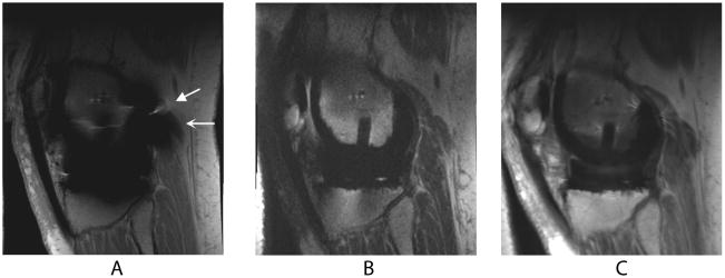
MRI was performed on 14 TKRs in 12 volunteers (5 men and 7 women; age range, 54–75 years). At the time of scanning, 5 knees were in volunteers who complained of pain and were dissatisfied. Scanning was performed with bandwidth ±125 kHz, slice thickness 3 mm, resolution 320×256, and field-of-view adjusted for knee size. FSE was acquired with repetition time/echo time (TR/TE)=3000/6.4 ms, 2 NEX, 36 slices, echo train length (ETL) 8 ms, and an average scan time of 5 minutes. SEMAC was obtained with TR/TE=2708/10 ms, 1 NEX, 2x auto calibrated parallel imaging (ARC) (11), 32 slices, ETL 8 ms, and an average scan time of 9:34. MAVRIC was acquired with TR/TE=3633/39.6 ms, 0.5 NEX, 2x ARC, 40 slices, ETL 24 ms, and an average scan time of 11:42. Both SEMAC and MAVRIC images were both reconstructed using a sum-of-squares combination (8)(Figs. 1, 2).
Figure 1.
Sagittal MR images of a TKR in a healthy volunteer. Metal-induced artifact including distortion (wedge-shaped arrow) and signal loss (curved arrow) severely limit the diagnostic value of FSE (a) images. SEMAC (b) and MAVRIC (c) correct for the artifact, allowing easier visualization of adjacent bone and soft tissue structures.
Figure 2.
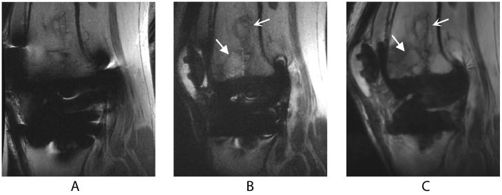
Sagittal images of a TKR produced by FSE (a), SEMAC (b), and MAVRIC (c) MRI pulse sequences in a volunteer who presented with knee pain at the time of scanning. The bone infarct (curved arrow) and presumed stress fracture (wedge-shaped arrow) are clearly seen on the SEMAC and particularly the MAVRIC images, but distortion obscures part of the fracture on the FSE image. The different apparent signal-to-noise ratios in these images can be attributed to the SEMAC image being combined using a linear, rather than a sum-of-squares, reconstruction.
For each knee, the medial and lateral femoral-tibial compartments were evaluated for two-dimensional artifact extent. Artifact was defined as signal void, pile-up, or distortion. The patellofemoral compartment was not evaluated for metal artifact, because these TKRs had included patellar components solely consisting of polyethylene. On the same anatomical slice for each compartment, the area of a region of interest encompassing the implant and surrounding artifact was measured by all three imaging techniques.
Abnormal axial alignment of the knee implant is an important cause of revision surgery, painful patellofemoral complications, and implant loosening (12–16). Implant rotation was analyzed in the TKR volunteers by measuring the combined femoral and tibial component rotation using the TKR methodology described by Berger et. al (13).
TKR Model
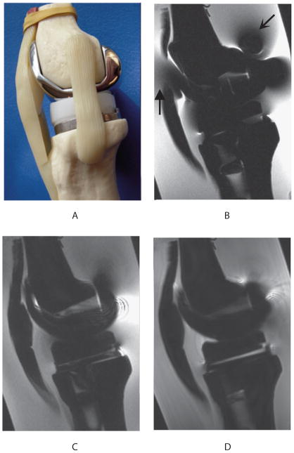
To evaluate the ability of the sequences in measuring geometry in the presence of metal, a custom-made model of the post-operative knee was scanned with each sequence in a similar manner to the TKR volunteers (Fig. 3). Receiver bandwidth was ±125 kHz for all sequences. FSE was acquired with TR/TE=3000/6.4 ms, 2 NEX, 36 slices, 3 mm slice thickness, resolution 320×256, ETL 8 ms, and an average scan time of 2:52. SEMAC was obtained with TR/TE=2539/9.3 ms, 1 NEX, 32 slices, 3 mm slice thickness, resolution 320×256, ETL 8 ms, and an average scan time of 2:54. MAVRIC was obtained with TR/TE=3700/43.5 ms, 0.5 NEX, 42 slices, 3 mm slice thickness, resolution 240×320, ETL 24 ms, and an average scan time of 2:52. Artifact was defined as geometric distortion in the TKR knee model because of its known dimensions.
Figure 3.
Sagittal view (a) of the custom-made model of the postoperative knee, consisting of plastic femoral and tibial bones (Zimmer, Warsaw, IN, USA) filled with oil to simulate subchondral fat, and fitted to standard TKR components (Zimmer NexGen LPS-Flex cobalt-chrome femoral component, polyethylene spacer, and Zimmer NexGen MIS Mini-Keel titanium tibial component). Water doped with copper sulfate surrounding the knee model simulates the MR relaxation properties of adjacent tissue in the knee. Sagittal MR imaging of the TKR knee model shows that FSE (b) had severe metal-induced distortion (wedge-shaped arrow) and signal loss (curved arrow) in comparison to SEMAC (c) and MAVRIC (d) images.
Using the Berger methodology (13) as in the TKR volunteers, the ability of each pulse sequence to measure TKR component rotation was assessed by comparing angles measured using the MR images to those measured on the reference standard, the TKR model. Measurements of the femoral and tibial component rotation angles on the MR images were repeated 10 times for each sequence. Accuracy in measuring the geometry of the TKR model was assessed by comparing the manufacturer’s known maximum anterior/posterior (A/P) and medial/lateral (M/L) dimensions of the metal femoral and tibial components and plastic spacer to the dimensions measured by the 3 sequences. Each A/P dimension measured by the pulse sequences is reported as the mean of the 2 A/P dimensions measured on the medial and lateral compartments for improved accuracy and as allowed for by the symmetry of the implant.
Patients
Clinical scanning with SEMAC included 11 patients (6 men and 5 women; age range, 25–83 years) with symptomatic knees, consisting of 8 TKRs, 2 large complex joint reconstructions, and 1 tibial plate. The knees were imaged primarily for clinical purposes, rather than for research investigation. Receiver bandwidth was ±125 kHz for all sequences. FSE-proton density (PD) was acquired with TR/TE=4000/26.3 ms, 1 NEX, 20 slices, 4 mm slice thickness, resolution 384×192, echo train length 6 ms, and an average scan time of 2:36. FSE-IR was acquired with TR/TE=4517/8.0 ms, 1.5 NEX, 20 slices, 4 mm slice thickness, resolution 256×192, inversion time 150 ms, ETL 8 ms, and an average scan time of 2:40. PD-SEMAC was obtained with TR/TE=3300/12.1 ms, 0.5 NEX, 32 slices, 3 mm slice thickness, resolution 256×192, ETL 8 ms, and an average scan time of 2:42. IR-SEMAC was obtained with TR/TE=3866/10.4 ms, 0.5 NEX, 32 slices, 3 mm slice thickness, resolution 256×192, ETL 8 ms, and an average scan time of 2:42. Artifact was defined as signal void, pile-up, or distortion. Artifact extent was compared between SEMAC and FSE by measuring on a central slice through the implant a region of interest encompassing the implant and metallic artifact. Changes in management such as surgery or follow-up after imaging of the patients were recorded.
Statistical Methods
Statistical analysis of the imaging techniques for artifact extent consisted of 2-factor repeated measures ANOVA with post-hoc paired comparisons. The data was log-transformed to correct for skewness, and the Greenhouse-Geisser epsilon used to correct for non-sphericity. Combined component rotation in the TKR volunteers was assessed by calculating the mean and standard deviation for each of the sequences. The actual and measured rotational alignments of the TKR knee model were compared by calculating differences, with the repeated measurements for precision analyzed with mean, standard deviation, and standard errors of estimated means. The difference between the actual and measured TKR model dimensions among the sequences is reported as a percent deviation. In addition, the measurements were compared with ordinary linear regression of difference on direction (A/P or M/L) and sequence, using FSE as the reference scan type and a post-hoc comparison of SEMAC versus MAVRIC. A robust variance estimation to compensate for the within-subject design was also applied. Multiple comparisons were accounted for by the Bonferroni correction, with a p value of less than 0.0083 considered to be significant. For the clinical scanning with SEMAC, the pairwise comparison between SEMAC and FSE for artifact extent was assessed with a mean difference in artifact extent and a paired t-test, with a p value of less than 0.05 for statistical significance.
RESULTS
Volunteers
FSE images had extensive artifact that obscured some periprosthetic soft tissue and bone, in contrast to the preserved anatomy and excellent intraosseous and soft tissue contrast depicted in the SEMAC and MAVRIC images (Figs. 1, 2). In one of the volunteers who presented with mild knee pain, imaging with SEMAC and MAVRIC led to the significant clinical finding of a suggested stress fracture that might have been missed by the standard FSE pulse sequence optimized for metal imaging (Fig. 2). This subtle bony pathology was not detected by plain radiography taken prior to the MRI scan.
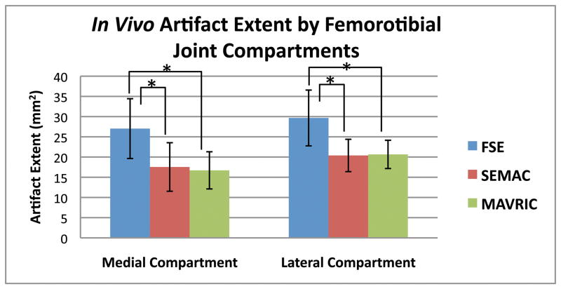
Measurements of artifact extent revealed a significant difference (p < 0.0001) among SEMAC, MAVRIC, and FSE. Post-hoc pairwise comparisons revealed that the statistical difference was due to SEMAC and MAVRIC measuring reduced artifact extent than FSE (all p < 0.0001), with SEMAC having 33% less artifact extent than FSE, and MAVRIC having 34% less artifact extent than FSE. SEMAC and MAVRIC were statistically equivalent to each other (p = 0.58, Fig. 4). The mean and standard deviation of the combined implant rotation were +5.5 ± 10.5° for FSE, +4.2 ± 7.5° for SEMAC, and +4.5 ± 6.2° for MAVRIC.
Figure 4.
Artifact extent measured on MR images of volunteers with TKRs showed that SEMAC and MAVRIC had significantly less artifact than conventional FSE images on all metal joint compartments of the knee (p < 0.0001). Correction of artifact is statistically similar between SEMAC and MAVRIC (p = 0.58). (* denotes statistical significance, p < 0.0083)
TKR Model
SEMAC and MAVRIC were able to measure TKR component rotation more accurately and precisely than FSE (Table 1). SEMAC and MAVRIC measured statistically smaller deviations compared to actual implant dimensions than FSE (all p < 0.0001), while being statistically similar to each other (p = 0.72) (Table 2). The exception is that FSE had the smallest deviation in measuring the A/P tibial component dimension (−1.6%) that was similar to the deviation produced by MAVRIC (−1.8%). For this dimension, SEMAC had its largest percent deviation of −4.6%. In all other TKR component dimensions of the femoral and tibial components and plastic tibial spacer, the range of absolute percent deviations was 1.6% to 24.8% for FSE, 1.0% to 4.6% for SEMAC, and 0.4% to 5.1% for MAVRIC.
Table 1.
Comparison of Measured and Known TKR Component Rotation Angles
| Rotation Angle (Difference) | ||||
|---|---|---|---|---|
| Mean±Standard Deviation | ||||
| Standard Error of the Estimated Mean | ||||
| TKR Component | Known | FSE | SEMAC | MAVRIC |
| Femoral Component | −1.0° | +3.2° (+4.2°) | −0.6° (+0.4°) | −0.3° (+0.7°) |
| 1.3±1.2° | −0.9±0.5° | −0.8±0.4° | ||
| 0.38° | 0.16° | 0.11° | ||
| Tibial Component | −17.0° | −21.1° (−4.1°) | −17.6° (−0.6°) | −17.8° (−0.8°) |
| −22.0±4.5° | −18.0±1.8° | −18.3±1.6° | ||
| 1.4° | 0.56° | 0.51° | ||
SEMAC and MAVRIC measured with more precision TKR component rotation angles similar to the angles measured on the TKR knee model, while rotation measured by FSE deviated to a larger extent.
Table 2.
Comparison of Measured and Known TKR Component Dimensions
| TKR Component Dimension | Length [cm] (Percent Deviation) |
|||
|---|---|---|---|---|
| Known | FSE | SEMAC* | MAVRIC* | |
| A/P Femur | 5.9 | 7.3 (+24.8%) | 5.6 (−3.4%) | 5.7 (−3.6%) |
| M/L Femur | 6.4 | 7.5 (+16.8%) | 6.5 (+2.0%) | 6.4 (+0.4%) |
| A/P Tibia | 4.2 | 4.1 (−1.6%) | 4.0 (−4.6%) | 4.1 (−1.8%) |
| M/L Tibia | 6.6 | 7.1 (+7.5%) | 6.5 (−2.2%) | 6.8 (+3.4%) |
| A/P Spacer | 4.2 | 4.7 (+10.8%) | 4.0 (−4.5%) | 4.0 (−5.1%) |
| M/L Spacer | 6.6 | 7.7 (+17.0%) | 6.7 (+1.0%) | 6.7 (+1.3%) |
A/P = anterior/posterior; M/L = medial/lateral
SEMAC and MAVRIC produced statistically smaller deviations from actual dimensions than FSE (p < 0.0001), while being statistically similar to each other (p = 0.72).
Patients
SEMAC significantly reduced artifact compared to FSE (p < 0.03). The mean difference in artifact extent between FSE and SEMAC was 21.1 cm2. In 9 of the 11 patients, findings on SEMAC images that were not visible or that were mistaken for artifact on FSE images were confirmed by subsequent patient management, including biopsy, joint aspiration, surgery, and other diagnostic studies (Table 3). One subject suffered a near-complete patellar tendon tear visible on SEMAC that may be mistaken for artifact on FSE images (Fig. 5) and confirmed at surgery for tendon repair. Another subject had recurrence of osteosarcoma in the prepatellar space visible on SEMAC, that then led to CT scanning for lung metastases, confirmed at biopsy (Fig. 6).
Table 3.
SEMAC imaging findings and subsequent patient management
| Subject Population (Number) | Imaging findings and changes in management (number) |
|---|---|
| Cancer Follow-Up (4): | Recurrent tumor on MRI; confirmed at biopsy (1) |
| Recurrent tumor on MRI; plan for surgery (1) | |
| Stable to follow-up (2) | |
| Painful Total Knee Replacements (7): | Peroneal nerve injury on MRI confirmed at EMG and nerve conduction studies (1) |
| Patellar tendon tear on MRI confirmed at surgery (1) | |
| Quadriceps tendon tear on MRI confirmed at ultrasound (1) | |
| Ganglion cyst on MRI confirmed at surgery (1) | |
| Ruled out hemangioma as source of pain; joint instability indicated revision surgery (1) | |
| Anatomically stable on MRI; referred to pain clinic (1) | |
| Large joint effusion; joint aspiration to rule out infection (1) |
Figure 5.
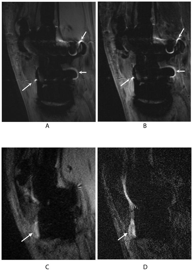
Bright signal pile-up on 2D-FSE PD (a) and 2D-FSE IR (b) images (curved arrows) may be confused with bright fluid signal in the PD-SEMAC (c) and IR-SEMAC (d) images (wedge-shaped arrows) used to diagnose a near-complete patellar tendon tear, confirmed at surgery for tendon repair.
Figure 6.
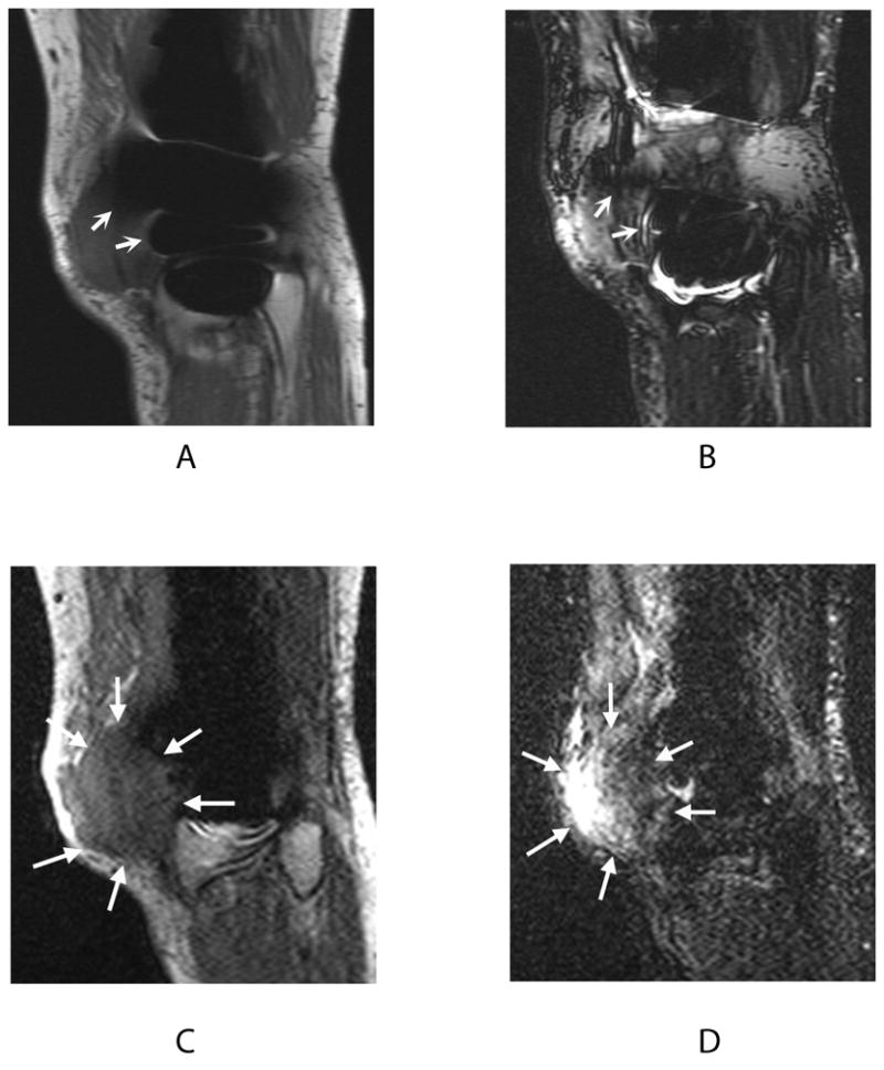
Signal loss in 2D-FSE PD (a) and 2D-FSE IR (b) images (curved arrows) obscures the full extent of recurrent osteosarcoma visible on PD-SEMAC (c) and IR-SEMAC (d) images (wedge-shaped arrows). This finding on SEMAC images led to computed tomography (CT) scanning for lung metastases, confirmed at biopsy.
DISCUSSION
The artifact produced by metal distorting the homogeneity of the main magnetic field has historically limited MR imaging around post-operative joints. Practical tips to minimize this artifact—including patient positioning, the use of FSE instead of standard spin or gradient echo pulse sequences, the use of inversion recovery instead of spectral selection for fat suppression, and the use of high bandwidth—have been reported in the literature (17,18). Ideally, there would be a MR imaging sequence that reduces metallic artifact, enabling the diagnostic value of MRI for postoperative complications such as infection or tumor recurrence.
Results from this study on both volunteers with TKRs and a TKR model demonstrate that SEMAC and MAVRIC correct for metal-induced artifacts, allowing them to accurately measure metal implant dimensions and rotation. In the clinical setting, SEMAC’s correction of artifact improved postoperative visualization of the knee, with imaging findings confirmed by subsequent non-invasive or invasive studies in 9 out of 11 highly symptomatic patients. Characteristic of MRI, SEMAC and MAVRIC produce high-resolution multiplanar images with excellent soft tissue and intraosseous contrast without the ionizing radiation of CT. Both SEMAC and MAVRIC are capable of proton-density, T1, T2 and STIR image contrast, all commonly used for orthopaedic imaging. Clear visualization of the bone/metal interface can allow for segmentation of a TKR component for its volume that could potentially be tracked to noninvasively monitor implant wear. Previous studies comparing optimized CT, optimized MR, and radiography for detection of osteolytic lesions found MRI to be the most sensitive and specific modality (19,20). Future research could study if SEMAC and MAVRIC are able to better quantify osteolysis, guiding revision arthroplasty and providing pharmaceutical research with a biomarker to test product efficacy.
A limitation to this study is that surgical correlation was not included for patients who did not undergo revision surgery. The TKR model with its known measurements has provided a standard by which to validate the accuracy of SEMAC and MAVRIC in measuring implant geometry and rotation. In the volunteers, the TKR implants were on average properly aligned, as components rotated between 0° and +10° have not been shown to present with patellofemoral complications (13). Another limitation is that this study did not compare measurements on FSE-IR with IR-SEMAC images. In addition, the imaging parameters for SEMAC and MAVRIC can be adjusted for different contrast, with these parameter changes possibly affecting the reduction in metal artifact. SEMAC and MAVRIC are MRI methods that are still under development so the relative results for these techniques may change as the technology evolves. Future studies can also include inter- and intraobserver variability to confirm the clinical measurements reported with more robust statistical analysis.
Metallic implants are increasingly used in our aging population. In addition to total joint replacement, metal implants are commonly used in spinal fusion, fracture fixation, and complex joint reconstruction after tumor resection. This last group is particularly problematic since follow-up imaging for tumor recurrence is currently limited to plain radiography or PET that lack the transverse plane alignment or soft tissue contrast, respectively, obtainable by artifact-free MRI. Our results with SEMAC in the knee support previous work investigating a variety of metallic implants (21), with SEMAC image findings confirmed by subsequent patient management in the symptomatic knee. SEMAC can also be acquired with inversion recovery for improved visualization of fluid, such as in the detection of bone marrow edema, tendon tears, or tumors (Figs. 5, 6) (22,23). Future development could add inversion recovery fat suppression and T1 weighting to the currently available PD and T2 weighting of MAVRIC. A current development of a hybrid method (24) merges the advantages of SEMAC and MAVRIC for imaging around metallic implants. The use of a “spectral localizer” scan (25) could also be explored to optimize imaging parameters for the hybrid method.
In conclusion, SEMAC and MAVRIC correct for the metal-induced artifact that has historically limited the clinical role of MR imaging around metal. By eliminating artifacts, SEMAC and MAVRIC non-invasively deliver the superb soft tissue contrast that we have come to expect of high-resolution MRI. These valuable imaging methods may help the radiologist in diagnosis and tracking of joint pathology and the orthopaedic surgeon in planning of initial and revision surgeries, ultimately improving patient care.
Acknowledgments
Contract grant sponsors: National Institutes of Health, The Wallace H. Coulter Foundation; GE Healthcare. Contract grant numbers: R21-EB008190, 1R01-EB002524, 1R01-EB005790.
We would like to acknowledge Jarrett Rosenberg, Ph.D., for his help with statistical analysis.
References
- 1.Kurtz S, Mowat F, Ong K, Chan N, Lau E, Halpern M. Prevalence of primary and revision total hip and knee arthroplasty in the United States from 1990 through 2002. J Bone Joint Surg Am. 2005;87(7):1487–1497. doi: 10.2106/JBJS.D.02441. [DOI] [PubMed] [Google Scholar]
- 2.St Clair EW, Yelin EH. In: Arthritis and Related Conditions. Jacobs JJ, Andersson GBJ, Bell J, Weinstein SL, editors. Rosemont, IL: American Academy of Orthopaedic Surgeons; 2008. [Google Scholar]
- 3.Resnick DL, Kransdorf MJ. Bone and Joint Imaging. London: Elsevier Health Sciences; 2004. [Google Scholar]
- 4.Wendt RE, 3rd, Wilcott MR, 3rd, Nitz W, Murphy PH, Bryan RN. MR imaging of susceptibility-induced magnetic field inhomogeneities. Radiology. 1988;168(3):837–841. doi: 10.1148/radiology.168.3.3406413. [DOI] [PubMed] [Google Scholar]
- 5.Butts K, Pauly JM, Gold GE. Reduction of blurring in view angle tilting MRI. Magn Reson Med. 2005;53(2):418–424. doi: 10.1002/mrm.20375. [DOI] [PubMed] [Google Scholar]
- 6.Cho ZH, Kim DJ, Kim YK. Total inhomogeneity correction including chemical shifts and susceptibility by view angle tilting. Med Phys. 1988;15(1):7–11. doi: 10.1118/1.596162. [DOI] [PubMed] [Google Scholar]
- 7.Lu W, Pauly KB, Gold GE, Pauly JM, Hargreaves BA. SEMAC: Slice Encoding for Metal Artifact Correction in MRI. Magn Reson Med. 2009;62(1):66–76. doi: 10.1002/mrm.21967. [DOI] [PMC free article] [PubMed] [Google Scholar]
- 8.Koch KM, Lorbiecki JE, Hinks RS, King KF. A multispectral three-dimensional acquisition technique for imaging near metal implants. Magn Reson Med. 2009;61(2):381–390. doi: 10.1002/mrm.21856. [DOI] [PubMed] [Google Scholar]
- 9.Koff MF, Koch KM, Potter HG. Magnetic Resonance Imaging of Periprosthetic Tissue in the Presence of Joint Arthroplasty. Proceedings of the 18th Annual Meeting of ISMRM; Stockholm, Sweden. 2010. (Abstract 131) [Google Scholar]
- 10.Rosset A, Spadola L, Ratib O. OsiriX: an open-source software for navigating in multidimensional DICOM images. J Digit Imaging. 2004;17(3):205–216. doi: 10.1007/s10278-004-1014-6. [DOI] [PMC free article] [PubMed] [Google Scholar]
- 11.Beatty PJ, Brau AC, Chang S, et al. A method for autocalibrating 2-D accelerated volumetric parallel imaging with clinically practical reconstruction times. Proceedings of the 15th Annual Meeting of ISMRM; Berlin, Germany. 2007. (Abstract 1749) [Google Scholar]
- 12.Oswald MH, Jakob RP, Schneider E, Hoogewoud HM. Radiological analysis of normal axial alignment of femur and tibia in view of total knee arthroplasty. J Arthroplasty. 1993;8(4):419–426. doi: 10.1016/s0883-5403(06)80042-2. [DOI] [PubMed] [Google Scholar]
- 13.Berger RA, Crossett LS, Jacobs JJ, Rubash HE. Malrotation causing patellofemoral complications after total knee arthroplasty. Clin Orthop Relat Res. 1998;(356):144–153. doi: 10.1097/00003086-199811000-00021. [DOI] [PubMed] [Google Scholar]
- 14.Fehring TK, Odum S, Griffin WL, Mason JB, Nadaud M. Early failures in total knee arthroplasty. Clin Orthop Relat Res. 2001;(392):315–318. doi: 10.1097/00003086-200111000-00041. [DOI] [PubMed] [Google Scholar]
- 15.Sharkey PF, Hozack WJ, Rothman RH, Shastri S, Jacoby SM. Insall Award paper. Why are total knee arthroplasties failing today? Clin Orthop Relat Res. 2002;(404):7–13. doi: 10.1097/00003086-200211000-00003. [DOI] [PubMed] [Google Scholar]
- 16.Eisenhuth SA, Saleh KJ, Cui Q, Clark CR, Brown TE. Patellofemoral instability after total knee arthroplasty. Clin Orthop Relat Res. 2006;446:149–160. doi: 10.1097/01.blo.0000214415.83593.db. [DOI] [PubMed] [Google Scholar]
- 17.Olsen RV, Munk PL, Lee MJ, et al. Metal artifact reduction sequence: early clinical applications. Radiographics. 2000;20(3):699–712. doi: 10.1148/radiographics.20.3.g00ma10699. [DOI] [PubMed] [Google Scholar]
- 18.Vandevenne JE, Vanhoenacker FM, Parizel PM, Butts Pauly K, Lang RK. Reduction of metal artefacts in musculoskeletal MR imaging. JBR-BTR. 2007;90(5):345–349. [PubMed] [Google Scholar]
- 19.Walde TA, Weiland DE, Leung SB, et al. Comparison of CT, MRI, and radiographs in assessing pelvic osteolysis: a cadaveric study. Clin Orthop Relat Res. 2005;(437):138–144. doi: 10.1097/01.blo.0000164028.14504.46. [DOI] [PubMed] [Google Scholar]
- 20.Potter HG, Nestor BJ, Sofka CM, Ho ST, Peters LE, Salvati EA. Magnetic resonance imaging after total hip arthroplasty: evaluation of periprosthetic soft tissue. J Bone Joint Surg Am. 2004;86-A(9):1947–1954. doi: 10.2106/00004623-200409000-00013. [DOI] [PubMed] [Google Scholar]
- 21.Gold G, Vasanawala S, Lu W, et al. MRI near metallic implants using SEMAC: initial clinical experience. Proceedings of the 18th Annual Meeting of ISMRM; Stockholm, Sweden. 2010. (Abstract 4361) [Google Scholar]
- 22.Hargreaves BALW, Butts-Pauly K, Pauly J, Gold GE. Fat-Suppressed and Distortion-Corrected MRI Near Metallic Implants. Proceedings of the 18th Annual Meeting of ISMRM; Stockholm, Sweden. 2010. (Abstract 3084) [Google Scholar]
- 23.Hargreaves BA, Chen W, Lu W, et al. Accelerated slice encoding for metal artifact correction. J Magn Reson Imaging. 2010;31(4):987–996. doi: 10.1002/jmri.22112. [DOI] [PMC free article] [PubMed] [Google Scholar]
- 24.Koch KM, Brau AC, Chen W, et al. Imaging near metal with a MAVRIC-SEMAC hybrid. Magn Reson Med. doi: 10.1002/mrm.22523. [DOI] [PubMed] [Google Scholar]
- 25.Hargreaves BA, Gold GE, Pauly JM, Pauly KB. Adaptive slice encoding for metal artifact correction. Proceedings of the 18th Annual Meeting of ISMRM; Stockholm, Sweden. 2010. (Abstract 3083) [Google Scholar]


