Abstract
We present a calculation of the microwave field distribution in a magic angle spinning (MAS) probe utilized in dynamic nuclear polarization (DNP) experiments. The microwave magnetic field (B1S) profile was obtained from simulations performed with the High Frequency Structure Simulator (HFSS) software suite, using a model that includes the launching antenna, the outer Kel-F stator housing coated with Ag, the RF coil, and the 4 mm diameter sapphire rotor containing the sample. The predicted average B1S field is 13µT/W1/2, where S denotes the electron spin. For a routinely achievable input power of 5 W the corresponding value is γ SB1S = 0.84 MHz. The calculations provide insights into the coupling of the microwave power to the sample, including reflections from the RF coil and diffraction of the power transmitted through the coil. The variation of enhancement with rotor wall thickness was also successfully simulated. A second, simplified calculation was performed using a single pass model based on Gaussian beam propagation and Fresnel diffraction. This model provided additional physical insight and was in good agreement with the full HFSS simulation. These calculations indicate approaches to increasing the coupling of the microwave power to the sample, including the use of a converging lens and fine adjustment of the spacing of the windings of the RF coil. The present results should prove useful in optimizing the coupling of microwave power to the sample in future DNP experiments. Finally, the results of the simulation were used to predict the cross effect DNP enhancement (ε) vs. ω1S/(2π) for a sample of 13C-urea dissolved in a 60:40 glycerol/water mixture containing the polarizing agent TOTAPOL; very good agreement was obtained between theory and experiment.
Keywords: Dynamic Nuclear Polarization, Instrumentation, Cryogenic MAS
1. Introduction
Magic angle spinning (MAS) nuclear magnetic resonance (NMR) is an effective method to extract biologically relevant structural constraints with sub-angstrom precision from a variety of different systems such as proteins embedded in native lipid bilayers [1, 2, 3, 4, 5, 6, 7, 8], antibiotics bound to bacterial cell walls in whole cells [9] and amyloid fibrils [10, 11, 12, 13, 14]. All three of these are examples of systems that are not accessible by either X-ray crystallography or solution NMR spectroscopy, the standard tools of structural biology. However, NMR detection of biomolecules in the solid state is inherently insensitive due to at least three factors. First, nuclear magnetic moments are very small, a property that yields long lived relaxation times and high-resolution spectra, but also results in weak Faraday induction and thus poor coupling to the RF coil. Second, investigating large macromolecular complexes in biologically relevant environments such as lipid bilayers or intact cells results in a low concentration of sites. Finally, detection in MAS experiments is typically performed on nuclei with a low gyromagnetic ratio (13C and 15N) rather than the more sensitive 1H detection prevalent in solution NMR. Dynamic nuclear polarization (DNP) is a powerful technique used to overcome these sensitivity issues in MAS experiments [15, 16, 17, 18, 19].
DNP dramatically improves the sensitivity of NMR experiments by transferring the large polarization of electron spins to bulk nuclei, a process which requires excitation of electron paramagnetic resonance (EPR) transitions with high-intensity millimeter wave radiation [20, 21]. Sensitivity enhancements of 50–300 on membrane proteins, amyloid fibrils, and microcrystalline peptides [18, 19, 22] are routine and are having a profound impact on biomolecular structural studies. Such results are due to the availability of stable, high-power gyrotrons as microwave sources [15, 23, 24], technical advances in cryogenic MAS [25, 26, 27] and the design of more effective polarizing agents [28, 29, 30].
DNP enhancements are dependent on a number of factors, and among the most important is the intensity of the microwave B1S field throughout the sample, where B1S denotes the component of the microwave magnetic field that is orthogonal to the Zeeman field B0 and oscillating in resonance with the electron spins. In MAS DNP experiments, the B1S field is generated by millimeter waves produced from an external source coupled to the sample via waveguides and/or quasioptics. However, due to the physical constraints imposed by the MAS probe, the design of an efficient mechanism for coupling the microwave power into the sample has proved challenging. These challenges include a high dielectric loss tangent of the sample, a cylindrical sapphire rotor, a large RF coil, the highly overmoded nature of the sample and the surrounding Kel-F stator.
Furthermore, the rotor is often filled with sample extending the entire length of the RF solenoid to increase the signal detected by the RF coil. This situation is in contrast to EPR/ENDOR resonators in which the sample occupies a small fraction of the volume where the B1S field is both uniform and intense [31]. For MAS DNP it is important to have a B1S field uniformly irradiating the sample in order to optimize the signal enhancements. Thus, the design and fabrication of a resonator with dimensions large compared to the microwave wavelength and containing a lossy dielectric sample is the paramount challenge in achieving large signal enhancements at high frequencies in MAS DNP experiments.
This paper presents two models used to analyze and predict the performance of microwave coupling to the sample in DNP experiments. The first approach utilizes the High Frequency Structure Simulator (HFSS) code [32] to model the electromagnetic fields within the MAS stator. The distribution of the microwave field in the sample is used to calculate the signal enhancement for a given input power. The second and approximate method is a single pass model based on Gaussian beam propagation and Fresnel diffraction that allows for quick inspection of the B1S field throughout the sample. Using this second method we are able to develop physical intuition about the impact that different components have on microwave coupling into the sample. However, the model includes some approximations that simplify the probe geometry in order to make an analytical solution possible. We also discuss implications of the results of these models for the optimization of microwave coupling and an understanding of the ω1S = γS B1S dependence of the DNP enhancement.
2. Physical Structure and Dielectric Constant
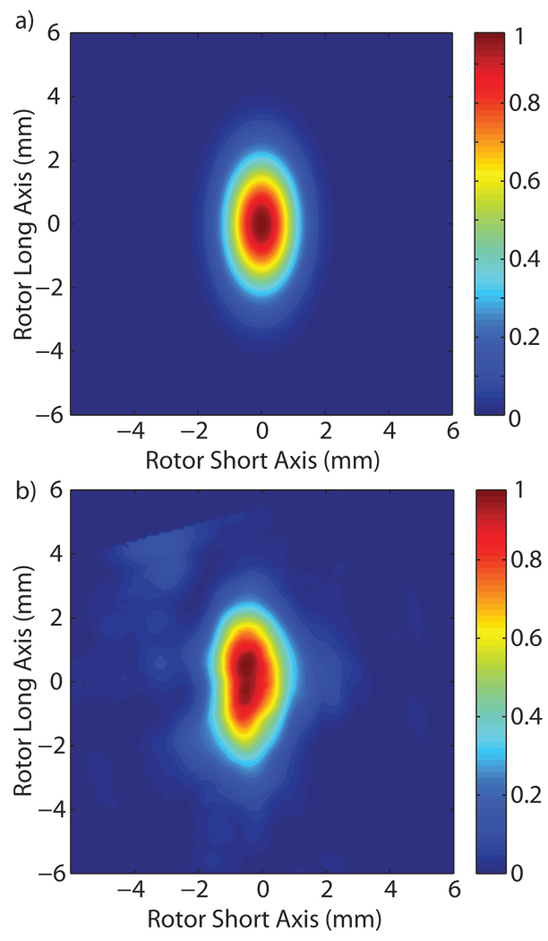
We characterized the microwave power distribution within the stator of a custom-built quadruple resonance (15N, 13C, 1H, e−) cryogenic sample-exchange DNP probe recently developed in our laboratory [25]. The microwave source for these experiments is a 250 GHz gyrotron oscillator developed at MIT [24, 33], capable of producing 15 W with a Gaussian beam output. The cross section of a Gaussian beam is defined as having an intensity profile given by , where wx and wy are the beam waists in the x and y direction, respectively. The microwave power is coupled from the gyrotron to the stator through corrugated waveguides and quasioptics, as described previously [25, 34]. After optimizing the alignment of the system, the microwave beam entering the stator was imaged 12 mm from the waveguide aperture, corresponding to the location of the sample, using a Spiricon Pyrocam III pyroelectric detector to verify the Gaussian beam content. Figure 1 shows excellent agreement between the pyroelectric camera image and an ideal Gaussian beam being radiated from an 8 mm corrugated waveguide into free space. The radiated beam is 93% Gaussian with a waist of 3.1 mm in the rotor radial axis direction and 3.4 mm in the rotor long axis direction, determined by finding the best fit for a 2D Gaussian. The white box in Figure 1(a) delineates the sample region. The optimization of overlap between the sample and the Gaussian beam using a cylindrical converging lens is discussed in Section 7.
Figure 1.
Microwave irradiation into the stator housing (a) for an ideal Gaussian beam emitted from the end of an 8 mm corrugated waveguide and radiated to a distance of 12 mm from the waveguide end, corresponding to the location of the sample, compared to (b) the measured output. (c) A cross section of the stator and DNP MAS probe showing the coil, sample, waveguide, and drive-cup and bearings of the spinning assembly.
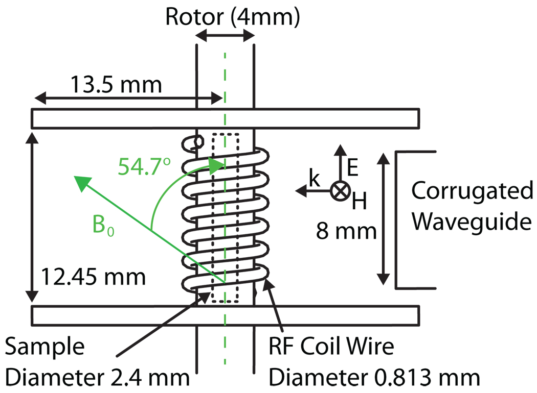
The probe geometry as modeled in HFSS is shown in Figure 2. The MAS stator module houses a cylindrical sapphire rotor with an outside diameter of 4 mm and oriented at 54.7° with respect to B0. Rotors with an inside diameter (ID) ranging from 2.1 to 2.8 mm were tested, with the optimal results obtained for an ID of 2.4 mm. A rotor with this ID accommodates ~56 µl of the cryo-protected sample of interest. A cylindrical Kel-F stator with a radius of 13.5 mm and a height of 12.45 mm encloses the entire RF coil and sample assembly. The leads of the RF coil enter from the side of the stator and form a 6.5 turn solenoid, wrapped from 0.8 mm diameter (20 gauge) silver-plated copper wire. A corrugated 8 mm cylindrical waveguide launches microwave power into the stator towards the sample (Figure 1c and 2).
Figure 2.
Cavity schematic as modeled in HFSS. The waveguide input is on the right.
The dielectric constant of the sample must be known in order to accurately model the microwave coupling. Our standard sample is 1 M 13C-urea and 10 mM TOTAPOL [28, 29] dissolved in a cryo-protecting matrix consisting of d8-glycerol/D20/H20 (60/30/10)% by volume. The dielectric constant of this matrix at 77 K was measured at 140 GHz using a vector network analyzer; the real part was 3.5±0.1 with a loss tangent of 0.005±0.0005. The dielectric constant was determined by measuring transmission through a thin planar sample of the matrix from 90–147 GHz and fitting the Fabry-Perot resonances to determine the real and imaginary part of the dielectric constant; the loss tangent is defined as tanδ = εi/εr. Based on typical properties of similar materials such as ice at low temperatures, we estimate that the real part of the dielectric constant will vary only slightly with frequency, while the imaginary part will increase approximately linearly with frequency [35, 36]. To obtain the dielectric constant at 250 GHz, we scaled the 140 GHz values, keeping the real part constant (3.5) and scaling the loss tangent linearly with frequency (0.009). The general conclusions of this study are not critically dependent on the exact values of these parameters, which will likely vary with sample content.
3. HFSS Model
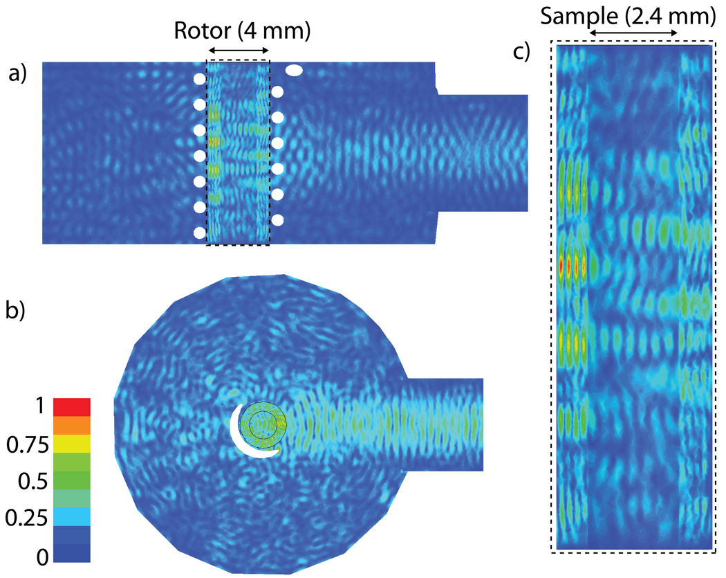
The precise B1S field distribution was obtained using a full 3D HFSS model of the stator, as shown in Figure 2. A cylindrical Kel-F stator that is not fully illustrated in Figure 2, but was included in the model, encloses the RF coil and rotor. The inside wall of the stator was partially coated with Ag [25] in order to increase the confinement of the microwave radiation. The coating’s effectiveness is limited because power escapes through holes required for the rotor bearing and drive gas and the high voltage leads of the RF coil. The magnitude of B1S, the transverse component of the magnetic field, can be seen in Figure 3. The microwave magnetic field in the sample is linearly polarized. The linearly polarized microwave field can be decomposed into two circularly polarized components, only one of which contributes to the excitation of electron spins. Figure 3 plots the normalized magnitude of the magnetic field, therefore the distribution is the same regardless of whether the field is linearly or circularly polarized. Figure 3(a) is a cross section of the center of the probe along the vertical axis of the sample, Figure 3(b) is a cross section of the center of the probe perpendicular to the vertical axis of the rotor, and Figure 3(c) is an expanded image of the sapphire rotor and sample region for the same cross section shown in Figure 3(a). Several items of interest appear in the HFSS model. First, a standing wave develops at the input port of the probe, seen as peaks and nulls in the magnitude of B1S, due to the large reflection from the RF coil. Second, the diffractive nature of the waves transmitted through the windings of the RF coil, which have a wire diameter on the order of a wavelength, are manifest as local maxima and minima along the vertical axis of the rotor. Third, reflections, especially in the silver coated Kel-F stator, create some standing wave inference fringes in the radial direction of the stator. Finally, the amplitude of the field decays towards the vertical extremes of the sample attenuating the signal enhancements produced in those regions.
Figure 3.
Normalized magnitude of B1S, the transverse component of the microwave magnetic field, for the (a) vertical cross section of the probe, (b) the horizontal cross section of the probe and (c) the rotor and sample cross section. The magnitude provides the maximum value of B1S allowing for the observation of the standing wave patterns present in the input and the horizontal direction of the sample, as well as the interference fringes from the RF coil in the vertical direction of the sample.
The HFSS simulations provide the electric and magnetic field throughout the stator. Using the known orientation of the sample, it is straight-forward to calculate the B1S value from the magnetic field. The software suite allows the user to perform simulations with progressively smaller mesh size to confirm that the solution becomes independent of grid size. The simulations and the B1S value converged with a mesh element volume of ~(100µm)3 yielding the spatial, time average B1S field of 13µT/W1/2. For a routinely achievable input power of 5 W the corresponding γsB1S = 0.84 MHz. The same calculation repeated without the silver coating of the stator yields 0.70 MHz for 5 W of input power. These values of B1S are obtained by first averaging the physically important quantity, which is , over the volume of the sample and then taking a square root.
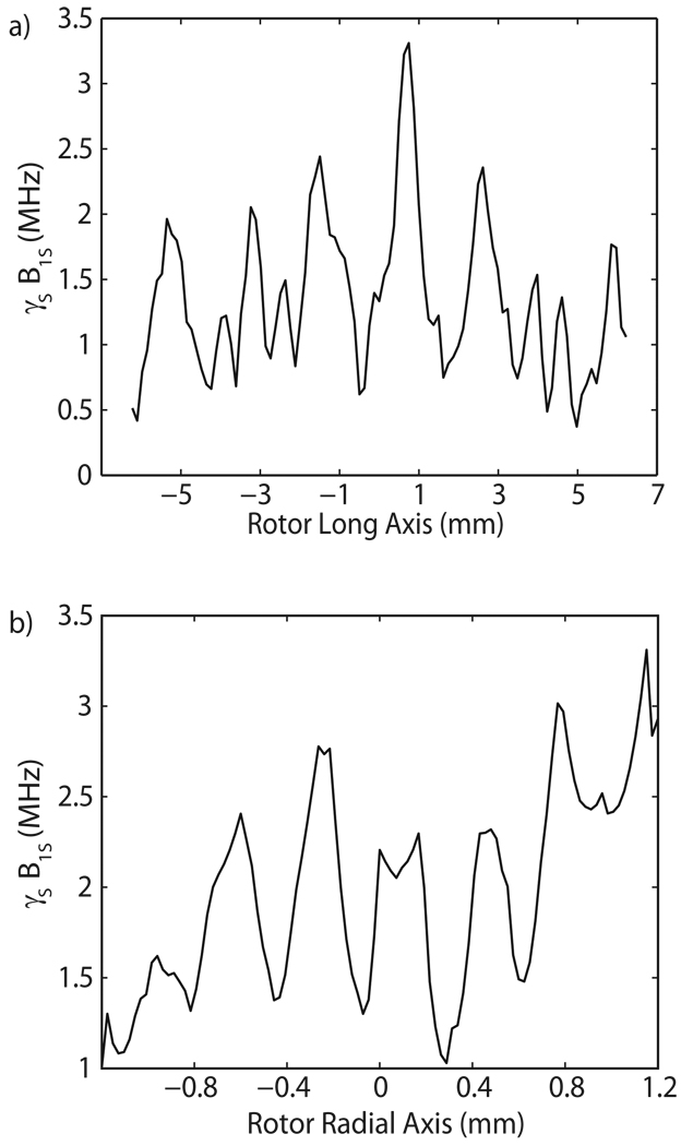
Axial and radial distributions of γsB1S for an input power of 5 W can be seen in Figure 4. Once again, the diffractive effect of the RF coil is evident in the vertical direction, and standing wave inference fringes are seen in the radial direction. Figures 3 and 4 illustrate the extremely inhomogenous irradiation that the sample receives from the Gaussian beam launched by the overmoded corrugated waveguide. In the sample, the γsB1S values range from 0.1 MHz to 4 MHz. This nonuniform distribution of γsB1S impacts the effectiveness of the probe, especially in the case of large volume samples. Calculating enhancements for a given γsB1S distribution in the sample taken from the HFSS model will be discussed in Section 4.
Figure 4.
Axial profile at (a) r = 0.6 mm and (b) radial profile at z = 0 mm.
An additional advantage of the HFSS model is the ability to track power flow through the stator. The thermal energy deposited in the sample must be considered because of the inverse dependence of enhancement on temperature [37]. The HFSS model indicates that the incident power is distributed as 5% deposited into the sample, 35% reflected back through the input port and 60% radiated from the ends of the rotor or deposited ohmically in the stator and RF coil.
4. Dependence of ε on ω1S
The HFSS simulation, together with a knowledge of the DNP mechanism, permits us to examine the dependence of the DNP signal enhancement (ε) on the microwave field strength, ω1S = γsB1S. When TEMPO based radicals are used as polarizing agents, then the primary high field DNP mechanism is the cross effect (CE) which involves two electrons and a nuclear spin. Specifically, the EPR spectrum of TEMPO is dominated by the g-anisotropy and satisfies the inequality Δ > ω0I > δ , where Δ is the inhomogeneous breadth of the spectrum, ω0I is the nuclear Larmor frequency, and δ is the homogeneous EPR linewidth. Thus, at high fields the Larmor frequency separation of two electrons S1 and S2 can be matched to the nuclear Larmor frequency, ω0S1 − ω0S2 = ω0I. Microwave irradiation flips S1 that is dipolar coupled to S2 and the difference in energy goes into polarizing the nuclear reservoir. Kessenikh, et al. [38, 39, 40] first described the CE In the limit of infinite ω1S. Subsequently, Hwang and Hill [41, 42] extended the theory to account for finite B1S ’s, but did not allow for leakage. Leakage was introduced by Wollan [43, 44] by modifying the rate equations of Hwang and Hill to examine the case of a well-resolved CE, two narrow EPR lines at ω0S1 and ω0S2 separated by exactly ω0I . These results were then extended to the case of an inhomogeneously broadened EPR spectrum with N unresolved spin packets that leads to an expression for the steady state enhancement. This treatment is applicable to the experimental situation presented by biradical polarizing agents such as BTnE [28, 45], TOTAPOL [29] and bTbk [30] where the e−-e− dipole couplings are ~20–30 MHz. Recently, the CE has been treated quantum mechanically with a particular emphasis on understanding and optimizing the enhancements available with biradicals [46].
Using classical rate equations, Wollan derived the following expression for the steady state enhancement, ESS, in a CE experiment
| (1) |
Here the G(ω)’s are the normalized EPR lineshape functions with ω0S the center of the lineshape, (ω0S) denoting the frequency of microwave irradiation, (ω0S ± ω0I) the solid effect frequencies, and ξ is the width of the spin packet, assumed to be rectangular, in the inhomogeneously broadened lineshape. The difference in the last factor represents the difference between spin packet populations. is the CE saturation parameter where is the transition probability for the inhomogeneously broadened (IHB) line and accounts for all modes of spin lattice relaxation other than that due to the CE. We take , and refer the reader to Wollan’s paper [43] for a discussion of this point. Thus, for a given irradiation frequency in the EPR spectrum, the last three factors on the RHS of Eqn. (1) are constant. Furthermore, we identify ESS with ε, assume that ε ≫ 1, and incorporate the constants into εmax to obtain the simplified expression
| (2) |
Again following Wollan, S0 = W0T1S, , and we approximate g(ω) = (T2s/π) which yields
| (3) |
Since the microwave field, ω1S, is inhomogeneous, as demonstrated in Figures 3 and 4, we integrate the expression over the field dependence for the sample volume
| (4) |
where now α=(T1S T2S)/2. The factor of 1/2 converts from the time averaged linearly polarized to the time averaged circularly polarized component that interacts with the electrons.
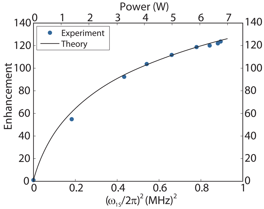
T1S for a Nitroxide radical is expected to range from 10–400 µs in the 90 Kelvin temperature regime, and T2S is a strong function of radical concentration being in the range of 10 to 200 ns for the 20 mM electron concentration in our sample. The magnitude of the product to obtain the quadratic dependence observed at low . It then saturates at high . Figure 5 is a plot of the experimental enhancement vs. ω1S/2π at 250 GHz for the sample and probe described in Figures 1 and 2 and the field distribution shown in Figures 3 and 4. An excellent fit to the experimental data is obtained for the parameters εmax = 230, T1S T2S=8×10⁻¹²s2. We emphasize that only by employing a volumetric integral that explicitly accounts for the large γS B1S fluctuations were we able to fit the enhancement curve with a T1S T2S factor that corresponds to published experimental values [47]. Calculating the value of γS B1S at the level of a mesh element volume defined by the HFSS model is crucial to understanding the DNP enhancement data and, indeed, to modeling the enhancement more generally obtained from the cross effect [43].
Figure 5.
DNP enhancement vs. (ω1S /(2π))2 (bottom) and power (top) for a fully packed rotor of 1 M13C-urea and 10 mM TOTAPOL [28, 29] dissolved in d8-glycerol/D20/H20 (60%/30%/10% by volume).
5. Rotor Wall Thickness
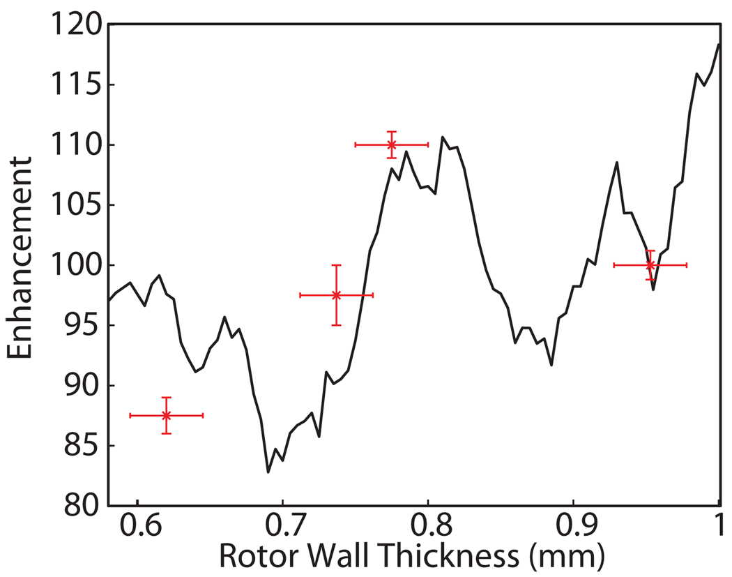
Minor modifications to the geometry of the rotor and stator can result in significant changes to the coupling of the microwave beam into the sample. For example, to optimize the rotor wall thickness, we have experimentally determined the DNP enhancement using rotors of varying wall thickness, and performed HFSS simulations in order to obtain an understanding of the influence of the rotor geometry on the microwave field strength in the sample. The outer radius of the rotor is constrained to 4 mm by the bearings that support the rotor during sample rotation, but the inner radius can be varied to maximize the coupling of microwave power to the sample. The sample diameter, equal to 4 mm minus twice the rotor wall thickness, was varied from 2.1 to 2.8 mm. Using Eqn. (4), we determined the expected enhancement from the γSB1S field distributions corresponding to wall thicknesses ranging from 0.6 to 1 mm, with the results shown in Figure 6. The predicted enhancements are in reasonable agreement with the experimental values determined for the four wall-thicknesses shown. This supports our approach to calculating the enhancement for a given field distribution and concurrently sets a precedent for further optimization of the DNP enhancement through geometrical considerations. As shown in Figure 6, a sample diameter of 2.4 mm maximizes enhancement and minimizes data acquisition time. Coincidently, this is the wall thickness used in commercial 4 mm rotors (Revolution NMR Ft. Collins, CO).
Figure 6.
Enhancement for a center-packed (5 mm length) sample as a function of rotor wall thickness.
Local maxima in the enhancement were observed near a rotor wall thickness of 0.6, 0.8 and 1 mm corresponding to peaks in transmission through the sapphire rotor wall. The general downward trend with decreasing rotor thickness is due to the increased sample volume with correspondingly lower overall average γSB1S values for constant input power.
6. Single Pass Model
A single pass model was also used as a simple approximation for microwave irradiation of the sample. The input corrugated waveguide launches a Gaussian beam into the probe that propagates through the RF coil and sapphire rotor to the sample (Figure 2). The metallic coil acts as a grating causing the incident beam to be both transmitted, with diffraction into the sapphire rotor, as well as reflected. The transmitted radiation then passes through the sapphire rotor that acts as a cylindrical converging lens and focuses the beam as it propagates into the sample.
Using Gaussian beam propagation and Fresnel diffraction one can model this system with some approximations. The main assumption is the absence of multiple reflections, i.e. a single pass model. This assumption can be justified by the lack of coherence in the reflections caused by the highly overmoded, lossy and complex geometry of the sample region. A second approximation models the RF coil as a parallel array of cylindrical wires, also called a wire array or wire grating. The dominant feature of the present arrangement of the RF coil is the spacing to wavelength ratio [48, 49]. We note that resonances that can occur for certain wire diameter to spacing ratios require a 3D treatment as will be discussed in Section 7.
The advantage of the single pass model is its reduced computational requirements and a physically intuitive understanding of how components such as the RF coil and sapphire rotor behave. Using this model, the highly overmoded volume can be analyzed rapidly, and it is straight forward to add or modify simple dielectric or metallic structures to explore the change in behavior. The physical understanding of the role that the various components play in the probe geometry is achieved by modeling the components individually.
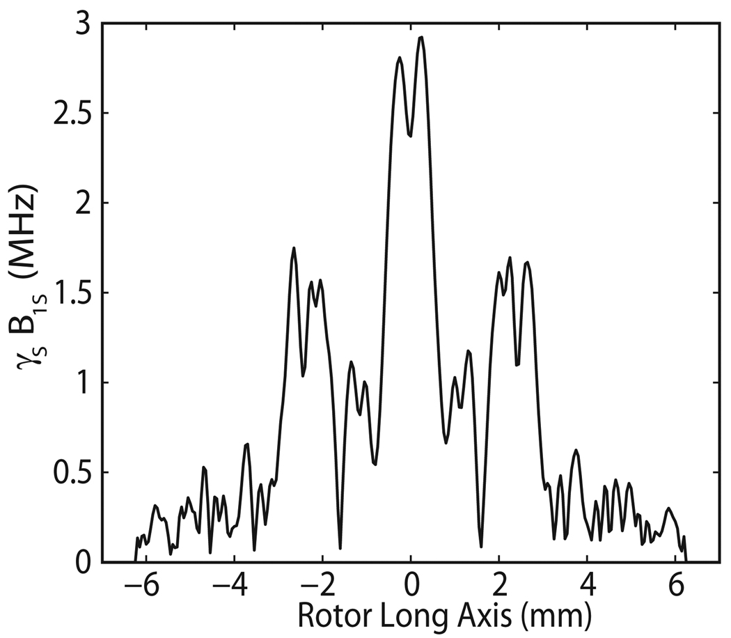
To calculate the average value of γSB1S in the sample a 5 W Gaussian beam with an initial waist of 2.6 mm was propagated from the corrugated waveguide to the surface of the RF coil. In the paraxial limit, the propagation of the Gaussian beam through vacuum is solely governed by initial beam waist. The power transmission through the RF coil was determined using published data [49]. Using Fresnel diffraction the beam is radiated past the coil. The Gaussian beam incident on the RF coil provides the illumination pattern that is the source term in the Fresnel diffraction integral. The transmission through the sapphire-sample boundary is calculated based on the incident angle. The microwave radiation no longer has a Gaussian distribution along the rotor long axis due to the diffractive effects of the wire array. However, in the plane perpendicular to the rotor long axis, the distribution is still Gaussian and this plane contains the curvature of the rotor that will focus the beam.
After performing these calculations, the single pass model yielded the highly non-uniform γSB1S distribution along the central axis of the sample shown in Figure 7. We calculated an average value of γSB1S = 0.70 MHz for an input of 5 W in the sample, in good agreement with the calculated value of 0.84 MHz from the more rigorous HFSS simulations.
Figure 7.
The γS B1S values along the long rotor axis calculated from an analytical diffraction treatment of power propagation into the sample
Considering these results, for a small sample volume located in the center of the rotor the average γSB1S value would be much higher than in a large sample volume that covers the full extent of the rotor long axis. However, in order to maximize the signal produced by the sample one would use a large sample volume. This is of great concern because a sample under test sees a wide range of γSB1S values leading to lower overall enhancements. Furthermore, this model indicates that only 77% of the radiated Gaussian beam power impinges on the sample; the RF coil allows for only 60% transmission [49]; and the calculated reflection coefficient for the sapphire-sample boundary averaged over the incident angle produces only 63% power transmission. These effects result in a large fraction of the power being wasted. Some possibilities to address this will be mentioned below.
7. Optimization of Coupling
In order to optimize coupling of the microwave power to the sample, we varied the rotor wall thickness and coated the inner surface of the Kel-F stator with silver[50]. One further improvement would be the use of a lens to focus the incident microwave power, avoiding power lost around the sample. We present here the design of a Teflon lens that is a step towards this goal.
In the first step of the analysis, we use the single pass model and ignore the effect of the RF coil on the coupling of the microwaves to the sample. The microwaves are launched from an antenna towards the sample. In our present configuration, the antenna is the end of an 8 mm diameter circular, corrugated waveguide. This antenna forms a circular Gaussian beam with a beam waist of 2.6 mm at the launching position. The sample is located about 12 mm from the launching antenna. The microwave beam waist increases slightly, from 2.6 mm to about 3.1 mm, in propagating from the launching antenna to the sample. The sample length is larger than the microwave beam size but the 2.4 mm sample diameter is smaller than the beam size. Fortunately, the sapphire rotor acts as a cylindrical converging lens that assists in coupling power into the sample. Nevertheless, we find that the sample only intercepts 77% of the microwave beam. This is largely because the Gaussian beam launched from the circular waveguide does not overlap optimally with the rectangular cross section of the sample. Therefore, a first improvement in coupling is to devise a cylindrically focusing lens that focuses the beam along the axis perpendicular to the long-axis of the rotor (Figure 8). This can be done with a specially shaped launching antenna or with a lens coupled to the existing antenna. Since an inexpensive lens can be made of a low loss, low dielectric constant material, it seems a simpler choice. Teflon was chosen because it has negligible absorption of microwaves at 250 GHz and it is easy to manufacture. Based on the single pass model the estimated increase in B1S, which goes as the square root of power, is about 13%. A Teflon lens with a radius of curvature of 5 mm was designed to maximize coupling by reducing the horizontal waist of the beam as seen in Figure 8(a) for the theoretical case and Figure 8(b) for the experimental case, as determined from the pyroelectric camera image. The radiated beam in Figure 8(b) is 90% Gaussian with a beam waist of 3.1 mm along the rotor long axis and 1.9 mm along the rotor diameter. HFSS simulations indicate that the average value of γSB1S should increase to 0.91 MHz from 0.84 MHz for an input power of 5 W, an increase of 8.6% in good agreement with the single pass model.
Figure 8.
(a) Ideal focused Gaussian beam and (b) the measured beam from a cylindrical dielectric focusing lens.
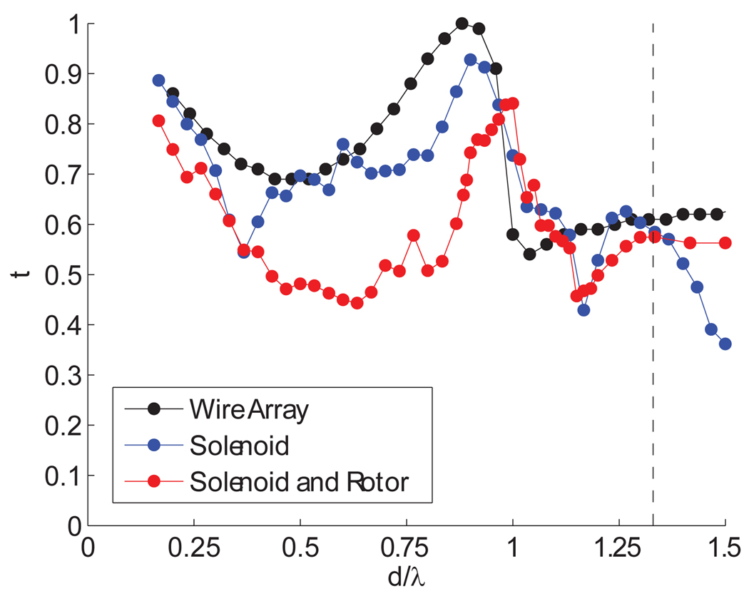
To further improve coupling, we consider the transmission through the RF coil, which is located between the waveguide and the sample. The transmission depends on the electric field polarization, which, in our case, is perpendicular to the wires. Using HFSS the transmission of a Gaussian beam through the coil was modeled for three geometries: a set of parallel metallic circular wires, a wire wrapped as a solenoid and the same solenoid wrapped around the sample filled rotor. In all cases the wire had a diameter a and center to center spacing d. The power transmission (t, where t=1 denotes full power transmission) results are shown in Figure 9. The transmission through the wire array, for wires that have no ohmic loss, is a function of the parameters (a,d) and the wavelength, λ, as shown in Figure 9. Using d/λ = 1.33 and a/d = 0.5 as in the current setup, HFSS simulations indicate the transmission, t, is 0.6. As shown in Figure 9, all three models produce similar results for d/λ = 1.33. The transmission can be improved, but we are limited by the curvature of the solenoid and the presence of the rotor. If the RF coil were optimally spaced at d/λ ≈ 1 a transmission value of 0.84 would be possible. This would further increase the B1S value by about 21%. We should also note that decreasing the a/d ratio uniformly improves the transmission of power through the RF coil [48, 49]. This has important implications for successfully extending DNP to higher fields and smaller rotor sizes, as it implies the microwave power could diffract efficiently through a tightly wound solenoid such as those currently used in high MAS frequency (>40 kHz) stators.
Figure 9.
Power transmission for a Gaussian beam radiated onto three models of the RF pickup coil with wire diameter a, spacing d and wavelength λ. The current spacing of d/λ = 1.33 is marked with a dashed line. All simulations were performed for an a/d = 0.5.
Combining these two improvements, namely the use of a lens and the proper spacing of the rotor windings, we can substantially increase the average B1S value. HFSS simulations including the cylindrically converging Teflon lens and improved wire spacing of d/λ = 1 and a/d = 0.5 showed an increase in the average value of γSB1S to 1.03 MHz from 0.84 MHz for an input power of 5 W, an increase of 23% in reasonable agreement with the single pass model.
8. Discussion and Conclusions
In the present experiments, the B1S value achieved in the sample is sufficient to reach satisfactory enhancement values with the available input power of 5 Watts. However, a more uniform distribution and improved coupling could produce greater enhancements. The current stator/coil arrangement produces a B1S value 13 µT/W1/2. In comparison, EPR and ENDOR resonators are able to achieve much higher average B1S values per W1/2 and improved homogeneity. Specifically, by using low order metallic resonant structures and sample volumes that occupy a small fraction of the resonator, B1S values on the order of 1 mT/W1/2 have been reported [51, 52, 53]. However, to optimize S/N in MAS DNP experiments, large sample volumes are required. Furthermore, metallic resonators or rotating metallic components are not permissible in the stator as they would produce eddy currents and levitation effects.
In addition to analyzing the current geometry of the probe, other input configurations were considered. Some time ago the use of axial coupling into the sample [15, 54, 55], whereby the microwaves are launched along the axis was investigated. Besides the added physical difficulty of coupling into the sample from along the axis, the relatively high loss tangent will cause the 12.5 mm long sample to see a highly non-uniform illumination, due to 67% of the power being absorbed as the wave propagates down the axis of the sample. Furthermore, with such a large sample volume and high loss tangent, the Q-factor will remain low even with the addition of reflective end caps. However, the utility of axial coupling could be optimized by full electromagnetic simulations to understand the determinants of the B1S value.
Using two methods we have analyzed the 250 GHz B1S field distribution throughout the sample in a 250 GHz / 380 MHz NMR DNP probe. The Gaussian beam propagation and Fresnel diffraction model proved effective in describing the effect of the Gaussian beam, RF coil, dielectric loss tangent and wall thickness on the coupling of microwave power into the sample. Full 3D simulations including reflections were performed using HFSS. For the Ag coated stator the simulations yielded an average γSB1S in the sample of 0.84 MHz for 5 W of input power into the stator. HFSS simulations were used to calculate the enhancement of the NMR signal as a function of rotor wall thickness using the full distribution of the B1S field in the sample. An optimized sample diameter of 2.4 mm (wall thickness of 0.8 mm) was found to maximize the DNP enhancement. Further improvements to the probe were characterized including silver coating the inside of the stator, adding a cylindrical lens and optimizing the RF coil spacing.
Acknowledgments
This research was supported by the National Institutes of Health through grants EB002804, EB003151, EB002026, EB001960, EB001035 and EB004866. A.B.B. was partially supported by graduate research fellowship from the National Science Foundation. We thank Albert Smith for helpful discussions.
Footnotes
Publisher's Disclaimer: This is a PDF file of an unedited manuscript that has been accepted for publication. As a service to our customers we are providing this early version of the manuscript. The manuscript will undergo copyediting, typesetting, and review of the resulting proof before it is published in its final citable form. Please note that during the production process errors may be discovered which could affect the content, and all legal disclaimers that apply to the journal pertain.
References
- 1.Creuzet F, McDermott A, Gebhard R, van der Hoef K, Spijker-Assink M, Herzfeld J, Lugtenburg J, Levitt M, Griffin R. Determination of membrane protein structure by rotational resonance NMR: bacteriorhodopsin. Science. 1991;251:783–786. doi: 10.1126/science.1990439. [DOI] [PubMed] [Google Scholar]
- 2.Li Y, Berthold D, Gennis R, Rienstra C. Chemical shift assignment of the transmembrane helices of DsbB, a 20-kDa integral membrane enzyme, by 3D magic-angle spinning NMR spectroscopy. Protein Science. 2008;17:199–204. doi: 10.1110/ps.073225008. [DOI] [PMC free article] [PubMed] [Google Scholar]
- 3.Nevzorov A, Park S, Opella S. Three-dimensional experiment for solid-state NMR of aligned protein samples in high field magnets. Journal of Biomolecular NMR. 2007;37:113–116. doi: 10.1007/s10858-006-9121-y. [DOI] [PubMed] [Google Scholar]
- 4.Cady S, Goodman C, Tatko C, DeGrado W, Hong M. Determining the orientation of uniaxially rotating membrane proteins using unoriented samples: a 2H, 13C, and 15N solid-state NMR investigation of the dynamics and orientation of a transmembrane helical bundle. Journal of the American Chemical Society. 2007;129:5719–5729. doi: 10.1021/ja070305e. [DOI] [PubMed] [Google Scholar]
- 5.Cady S, Hong M. Amantadine-induced conformational and dynamical changes of the influenza M2 transmembrane proton channel. Proceedings of the National Academy of Sciences. 2008;105:1483–1488. doi: 10.1073/pnas.0711500105. [DOI] [PMC free article] [PubMed] [Google Scholar]
- 6.Cady S, Mishanina T, Hong M. Structure of amantadine-bound M2 transmembrane peptide of influenza A in lipid bilayers from magic-angle-spinning solid-state NMR: the role of Ser31 in amantadine binding. Journal of Molecular Biology. 2009;385:1127–1141. doi: 10.1016/j.jmb.2008.11.022. [DOI] [PMC free article] [PubMed] [Google Scholar]
- 7.Moffat J, Vijayvergiya V, Gao P, Cross T, Woodbury D, Busath D. Proton transport through influenza A virus M2 protein reconstituted in vesicles. Biophysical Journal. 2008;94:434–445. doi: 10.1529/biophysj.107.109082. [DOI] [PMC free article] [PubMed] [Google Scholar]
- 8.Song Z, Kovacs F, Wang J, Denny J, Shekar S, Quine J, Cross T. Transmembrane domain of M2 protein from influenza A virus studied by solid-state 15N polarization inversion spin exchange at magic angle NMR. Biophysical Journal. 2000;79:767–775. doi: 10.1016/S0006-3495(00)76334-X. [DOI] [PMC free article] [PubMed] [Google Scholar]
- 9.Kim S, Matsuoka S, Patti G, Schaefer J. Vancomycin derivative with damaged d-Ala-d-Ala binding cleft binds to cross-linked peptidoglycan in the cell wall of staphylococcus aureus. Biochemistry. 2008;47:3822–3831. doi: 10.1021/bi702232a. [DOI] [PMC free article] [PubMed] [Google Scholar]
- 10.Jaroniec C, MacPhee C, Bajaj V, McMahon M, Dobson C, Griffin R. High-resolution molecular structure of a peptide in an amyloid fibril determined by magic angle spinning NMR spectroscopy. Proceedings of the National Academy of Sciences. 2004;101:711–716. doi: 10.1073/pnas.0304849101. [DOI] [PMC free article] [PubMed] [Google Scholar]
- 11.Petkova A, Ishii Y, Balbach J, Antzutkin O, Leapman R, Delaglio F, Tycko R. A structural model for Alzheimer’s β-amyloid fibrils based on experimental constraints from solid state NMR. Proceedings of the National Academy of Sciences. 2002;99:16742. doi: 10.1073/pnas.262663499. [DOI] [PMC free article] [PubMed] [Google Scholar]
- 12.Tycko R. Progress towards a molecular-level structural understanding of amyloid fibrils. Current Opinion in Structural Biology. 2004;14:96–103. doi: 10.1016/j.sbi.2003.12.002. [DOI] [PubMed] [Google Scholar]
- 13.van der Wel P, Lewandowski J, Griffin R. Solid-state NMR study of amyloid nanocrystals and fibrils formed by the peptide GNNQQNY from yeast prion protein Sup35p. Journal of the American Chemical Society. 2007;129:5117–5130. doi: 10.1021/ja068633m. [DOI] [PubMed] [Google Scholar]
- 14.Bayro M, Maly T, Birkett N, MacPhee C, Dobson C, Griffin R. High-resolution MAS NMR analysis of PI3-SH3 amyloid fibrils: Backbone conformation and implications for protofilament assembly and structure. Biochemistry. 2010;49:7474–7488. doi: 10.1021/bi100864t. [DOI] [PMC free article] [PubMed] [Google Scholar]
- 15.Becerra L, Gerfen G, Temkin R, Singel D, Griffin R. Dynamic nuclear polarization with a cyclotron resonance maser at 5 T. Physical Review Letters. 1993;71:3561–3564. doi: 10.1103/PhysRevLett.71.3561. [DOI] [PubMed] [Google Scholar]
- 16.Gerfen G, Becerra L, Hall D, Griffin R, Temkin R, Singel D. High frequency (140 GHz) dynamic nuclear polarization: Polarization transfer to a solute in frozen aqueous solution. Journal of Chemical Physics. 1995;102:9494–9497. [Google Scholar]
- 17.Hall D, Maus D, Gerfen G, Inati S, Becerra L, Dahlquist F, Griffin R. Polarization-enhanced NMR spectroscopy of biomolecules in frozen solution. Science. 1997;276:930–932. doi: 10.1126/science.276.5314.930. [DOI] [PubMed] [Google Scholar]
- 18.Rosay M, Lansing J, Haddad K, Bachovchin W, Herzfeld J, Temkin R, Griffin R. High-frequency dynamic nuclear polarization in MAS spectra of membrane and soluble proteins. Journal of the American Chemical Society. 2003;125:13626–13627. doi: 10.1021/ja036898k. [DOI] [PubMed] [Google Scholar]
- 19.Bajaj V, Mak-Jurkauskas M, Belenky M, Herzfeld J, Griffin R. Functional and shunt states of bacteriorhodopsin resolved by 250 GHz dynamic nuclear polarization–enhanced solid-state NMR. Proceedings of the National Academy of Sciences. 2009;106:9244–9249. doi: 10.1073/pnas.0900908106. [DOI] [PMC free article] [PubMed] [Google Scholar]
- 20.Barnes A, de Paepe G, van der Wel P, Hu K, Joo C, Bajaj V, Mak-Jurkauskas M, Sirigiri J, Herzfeld J, Temkin R, et al. High-field dynamic nuclear polarization for solid and solution biological NMR. Applied Magnetic Resonance. 2008;34:237–263. doi: 10.1007/s00723-008-0129-1. [DOI] [PMC free article] [PubMed] [Google Scholar]
- 21.Maly T, Debelouchina G, Bajaj V, Hu K, Joo C, Mak-Jurkauskas M, Sirigiri J, van der Wel P, Herzfeld J, Temkin R, et al. Dynamic nuclear polarization at high magnetic fields. Journal of Chemical Physics. 2008;128 doi: 10.1063/1.2833582. 052211. [DOI] [PMC free article] [PubMed] [Google Scholar]
- 22.van der Wel P, Hu K, Lewandowski J, Griffin R. Dynamic nuclear polarization of amyloidogenic peptide nanocrystals: GNNQQNY, a core segment of the yeast prion protein Sup35p. Journal of the American Chemical Society. 2006;128:10840–10846. doi: 10.1021/ja0626685. [DOI] [PubMed] [Google Scholar]
- 23.Becerra L, Gerfen G, Bellew B, Bryant J, Hall D, Inati S, Weber R, Un S, Prisner T, McDermott A, et al. A spectrometer for dynamic nuclear polarization and electron paramagnetic resonance at high frequencies. Journal of Magnetic Resonance, Series A. 1995;117:28–40. [Google Scholar]
- 24.Bajaj V, Hornstein M, Kreischer K, Sirigiri J, Woskov P, Mak-Jurkauskas M, Herzfeld J, Temkin R, Griffin R. 250 GHz CW gyrotron oscillator for dynamic nuclear polarization in biological solid state NMR. Journal of Magnetic Resonance. 2007;189:251–279. doi: 10.1016/j.jmr.2007.09.013. [DOI] [PMC free article] [PubMed] [Google Scholar]
- 25.Barnes A, Mak-Jurkauskas M, Matsuki Y, Bajaj V, Van der Wel P, DeRocher R, Bryant J, Sirigiri J, Temkin R, Lugtenburg J, et al. Cryogenic sample exchange NMR probe for magic angle spinning dynamic nuclear polarization. Journal of Magnetic Resonance. 2009;198:261–270. doi: 10.1016/j.jmr.2009.03.003. [DOI] [PMC free article] [PubMed] [Google Scholar]
- 26.Samoson A, Tuherm T, Past J, Reinhold A, Anupõld T, Heinmaa I. New horizons for magic-angle spinning NMR. Topics of Current Chemistry. 2005;246:15–31. doi: 10.1007/b98647. [DOI] [PubMed] [Google Scholar]
- 27.Thurber K, Tycko R. Biomolecular solid state NMR with magic-angle spinning at 25 K. Journal of Magnetic Resonance. 2008;195:179–186. doi: 10.1016/j.jmr.2008.09.015. [DOI] [PMC free article] [PubMed] [Google Scholar]
- 28.Hu K, Yu H, Swager T, Griffin R. Dynamic nuclear polarization with biradicals. Journal of the American Chemical Society. 2004;126:10844–10845. doi: 10.1021/ja039749a. [DOI] [PubMed] [Google Scholar]
- 29.Song C, Hu K, Joo C, Swager T, Griffin R. TOTAPOL: A biradical polarizing agent for dynamic nuclear polarization experiments in aqueous media. Journal of the American Chemical Society. 2006;128:11385–11390. doi: 10.1021/ja061284b. [DOI] [PubMed] [Google Scholar]
- 30.Matsuki Y, Maly T, Ouari O, Karoui H, Le Moigne F, Rizzato E, Lyubenova S, Herzfeld J, Prisner T, Tordo P, et al. Dynamic nuclear polarization with a rigid biradical. Angewandte Chemie. 2009;121:5096–5100. doi: 10.1002/anie.200805940. [DOI] [PMC free article] [PubMed] [Google Scholar]
- 31.Weis V, Bennati M, Rosay M, Bryant J, Griffin R. High-field DNP and ENDOR with a novel multiple-frequency resonance structure. Journal of Magnetic Resonance. 1999;140:293–299. doi: 10.1006/jmre.1999.1841. [DOI] [PubMed] [Google Scholar]
- 32.HFSS Manual. Ansys Corp.; 2010. [Google Scholar]
- 33.Kreischer K, Farrar C, Griffin R, Temkin R, Vieregg J. The development of a 250 GHz cw gyrotron for EPR and NMR spectroscopy; Proceedings of the 24th International Conference on Infrared and Millimeter Waves; 1993. vol. Paper IU-A3. [Google Scholar]
- 34.Woskov P, Bajaj V, Hornstein M, Temkin R, Griffin R. Corrugated waveguide and directional coupler for CW 250-GHz gyrotron DNP experiments. IEEE Transactions on Microwave Theory and Techniques. 2005;53:1863–1869. doi: 10.1109/TMTT.2005.848097. [DOI] [PMC free article] [PubMed] [Google Scholar]
- 35.Jiang J, Wu D. Ice and water permittivities for millimeter and sub-millimeter remote sensing applications. Atmospheric Science Letters. 2004 2004;5:146–151. [Google Scholar]
- 36.Lamb J. Miscellaneous data on materials for millimetre and submillimetre optics. International Journal of Infrared and Millimeter Waves. 1996;17:1997–2034. [Google Scholar]
- 37.Rosay M, Tometich L, Pawsey S, Bader R, Schauwecker R, Blank M, Borchard P, Cauffman S, Felch K, Weber R, et al. Solid-state dynamic nuclear polarization at 263 GHz: spectrometer design and experimental results. Physical Chemistry Chemical Physics. 2010;12:5850–5860. doi: 10.1039/c003685b. [DOI] [PMC free article] [PubMed] [Google Scholar]
- 38.Kessenikh A, Lushchikov V, Manenkov A, Taran Y. Proton polarization in irradiated polyethylenes. Soviet Phys. Solid State. 1963;5:321–329. [Google Scholar]
- 39.Kessenikh A, Manenkov A. Dynamic polarization of nuclei during saturation of nonuniformly broadened electron paramagnetic resonance lines. Soviet Phys. Solid State. 1963;5:835–837. [Google Scholar]
- 40.Kessenikh A, Manenkov A, PIATNITSKII G. On explanation of experimental data on dynamic polarization of protons in irradiated polyethylenes(Dynamic polarization of protons in irradiated polyethylenes explained, using electron paramagnetic resonance, taking into account cross relaxation) Soviet Physics-Solid State. 1964;6:641–643. [Google Scholar]
- 41.Hwang C, Hill D. New effect in dynamic polarization. Physical Review Letters. 1967;18:110–112. [Google Scholar]
- 42.Hwang C, Hill D. Phenomenological model for the new effect in dynamic polarization. Physical Review Letters. 1967;19:1011–1014. [Google Scholar]
- 43.Wollan D. Dynamic nuclear polarization with an inhomogeneously broadened ESR line. I. Theory. Physical Review B. 1976;13:3671–3685. [Google Scholar]
- 44.Wollan D. Dynamic nuclear polarization with an inhomogeneously broadened ESR line. II. Experiment. Physical Review B. 1976;13:3686–3696. [Google Scholar]
- 45.Hu K, Song C, Yu H, Swager T, Griffin R. High-frequency dynamic nuclear polarization using biradicals: A multifrequency EPR lineshape analysis. Journal of Chemical Physics. 2008;128 doi: 10.1063/1.2816783. 052302. [DOI] [PubMed] [Google Scholar]
- 46.Hu K, Debelouchina G, Smith A, Griffin R. Quantum mechanical theory of dynamic nuclear polarization in solid dielectrics. Journal of Chemical Physics. doi: 10.1063/1.3564920. (submitted for publication) [DOI] [PMC free article] [PubMed] [Google Scholar]
- 47.Farrar C, Hall D, Gerfen G, Inati S, Griffin R. Mechanism of dynamic nuclear polarization in high magnetic fields. Journal of Chemical Physics. 2001;114:4922–4933. [Google Scholar]
- 48.Chambers W, Mok C, Parker T. Theory of the scattering of electromagnetic waves by a regular grid of parallel cylindrical wires with circular cross section. Journal of Physics A: Mathematical and General. 1980;13:1433. [Google Scholar]
- 49.Chambers W, Parker T, Costley A. Freestanding fine-wire grids for use in millimeter-and submillimeter-wave spectroscopy. Infrared and Millimeter Waves: Electromagnetic Waves in Matter. 1986:77. [Google Scholar]
- 50.Rosay M, Zeri A, Astrof N, Opella S, Herzfeld J, Griffin R. Sensitivity-enhanced NMR of biological solids: Dynamic nuclear polarization of Y21M fd bacteriophage and purple membrane. Journal of the American Chemical Society. 2001;123:1010–1011. doi: 10.1021/ja005659j. [DOI] [PubMed] [Google Scholar]
- 51.Denysenkov V, Prandolini M, Krahn A, Gafurov M, Endeward B, Prisner T. High-field DNP spectrometer for liquids. Applied Magnetic Resonance. 2008;34:289–299. [Google Scholar]
- 52.Annino G, Villanueva-Garibay J, van Bentum P, Klaassen A, Kentgens A. A high-conversion-factor, double-resonance structure for high-field dynamic nuclear polarization. Applied Magnetic Resonance. 2010;37:851–864. [Google Scholar]
- 53.Thurber K, Yau W, Tycko R. Low-temperature dynamic nuclear polarization at 9.4 T with a 30 mW microwave source. Journal of Magnetic Resonance. 2010;204:303–313. doi: 10.1016/j.jmr.2010.03.016. [DOI] [PMC free article] [PubMed] [Google Scholar]
- 54.Matsuki Y, Takahashi H, Ueda K, Idehara T, Ogawa I, Toda M, Akutsu H, Fujiwara T. Dynamic nuclear polarization experiments at 14.1 T for solid-state NMR. Physical Chemistry Chemical Physics. 2010;12:5799–5803. doi: 10.1039/c002268c. [DOI] [PubMed] [Google Scholar]
- 55.Afeworki M, McKay R, Schaefer J. Selective observation of the interface of heterogeneous polycarbonate/polystyrene blends by dynamic nuclear polarization carbon-13 NMR spectroscopy. Macromolecules. 1992;25:4084–4091. [Google Scholar]


