Abstract
This paper presents a new type of pneumatic motor, a pneumatic step motor (PneuStep). Directional rotary motion of discrete displacement is achieved by sequentially pressurizing the three ports of the motor. Pulsed pressure waves are generated by a remote pneumatic distributor. The motor assembly includes a motor, gearhead, and incremental position encoder in a compact, central bore construction. A special electronic driver is used to control the new motor with electric stepper indexers and standard motion control cards. The motor accepts open-loop step operation as well as closed-loop control with position feedback from the enclosed sensor. A special control feature is implemented to adapt classic control algorithms to the new motor, and is experimentally validated. The speed performance of the motor degrades with the length of the pneumatic hoses between the distributor and motor. Experimental results are presented to reveal this behavior and set the expectation level. Nevertheless, the stepper achieves easily controllable precise motion unlike other pneumatic motors. The motor was designed to be compatible with magnetic resonance medical imaging equipment, for actuating an image-guided intervention robot, for medical applications. For this reason, the motors were entirely made of nonmagnetic and dielectric materials such as plastics, ceramics, and rubbers. Encoding was performed with fiber optics, so that the motors are electricity free, exclusively using pressure and light. PneuStep is readily applicable to other pneumatic or hydraulic precision-motion applications.
Index Terms: Image-guided intervention, magnetic resonance imaging (MRI) compatibility, medical robotics, pneumatic hydraulic motor, step motor, stepper
I. Introduction
Pneumatic actuation is commonly used in industrial and commercial applications for its low cost, compact size, high power-to-weight ratio, reliability, and low maintenance. In many cases, these characteristics make it preferable over electric actuation, especially when a supply of air is readily available. The major limitation of classic pneumatic actuators, rotary or linear, has been their reduced precision in controlled motion [1]. This is mainly caused by air compressibility and friction in the valve [2] and actuator, which make the pump-line-actuator dynamic system highly nonlinear. Novel hardware [3], [4] and pneumatic-servo control [5], [6] solutions have been proposed to cope with these problems, and impressive results have been achieved in force control [7], [8] and speed regulation [9]. Nevertheless, these complex solutions require special care, and so most practical applications are still limited to unregulated pneumatic motion.
Alternatively, this paper presents a new approach, which, in certain applications, may circumvent the pneumatic-servo problems, by introducing a pneumatic step motor.
Somewhat similarly, steam engines operate on the pressure of steam, and motion could be quantified with each stroke of the piston. In fact, several pneumatic motors include such designs, e.g., a British company1 makes a series of three-cylinder air motors with a central output crank. The crank engages a rotary air distributor, which commutes the air supply to the three cylinders. Most recently, the company added proximity sensors to the cylinder heads for encoding the strokes of the piston. Despite their claim, Dynatork motors are not step motors because they operate on a continuous supply of air with internal commutation, thus being better compared with brushed dc electric motors. Dynatork motors cannot take and hold a step command. PneuStep is the result of four years of experimental research. We have also reported several other versions of hydraulic stepper motors [10]. One of those versions, the “harmonic motor” is somewhat similar to an earlier pneumatic motor reportedly applied to an industrial paper mill machine in the 1980s [11]. Harmonic motors use fluid power to deform the flex spline of a harmonic drive in place of the common mechanic wave generator. Another version that we previously reported, the “planetary motor” [10], is the latest precursor of the PneuStep design presented here.
This development was performed for medical applications, under a project for creating a robot that can precisely operate within the closed bore of high-intensity magnetic resonance imaging (MRI) equipment. This allows for performing remote procedures within the scanner under MRI guidance. The diagnostic and therapy potential of the system is very significant, because MRI is the preferred method for imaging soft tissues. The image provides a roadmap for manipulating the robot. This could allow, for example, to insert a needle precisely at the center of a small tumor visualized in the image for performing a tumor-centered biopsy. Today, biopsy procedures are typically performed with randomized sampling techniques. The use of the robot could reduce the incidence of false negative sampling. A robot actuated with PneuStep motors has been completed and is now under evaluation.
Creating MRI robotics is a very challenging engineering task. MRI scanners use magnetic fields of very high density [up to several tesla (T)], with pulsed magnetic and radio frequency fields. Creating passive instrumentation for MRI interventions involves careful material selection with nonmagnetic and, preferably, dielectric properties [10]. In the case of active instrumentation, ensuring MRI compatibility is a much more difficult task, because, in addition, the energies involved in actuation and sensing should not interfere with the functionality of the imager.
Electromagnetic motors typically used in robotics are incompatible by principle. Robotic research in the field has unanimously utilized ultrasonic (piezoelectric) motors [12]–[15]. These are magnetism free, but still present conductive components and use electricity creating image distortions if operated closer than 0.5 m from the image isocenter [14]. Pneumatic actuation is a fundamentally flawless alternative for MRI compatibility. Pneumatics has been used in handheld drill-like instrumentation [16] and tested in robotic end-effector designs [14], but could not yet be involved in precisely controlled motion.
All our PneuStep prototypes are fully MRI compatible (MRI translucent, medically safe, and precise), being constructed of nonmagnetic and dielectric materials, using air pressure for motion, and light for fiber optic encoding. In other applications, the motor could be constructed of metallic components for increased mechanical performance and durability, and may potentially be operated hydraulically for higher torque/size ratios.
II. Motor Kinematics
The PneuStep invention is based on the simple remark that end-to-end motion of a piston within its cylinder is always exact. This can be achieved by simply pressurizing the cylinder, much easier than positioning the piston in midstroke with pneumatic-servo control. The step motor is designed to successively collect small end-to-end motion strokes in a rotary motion. A step is made by an end-of-stroke motion.
A new kinematic principle is used to induce the step motion and demultiply it (gear it down) with the same mechanism. The basic motor is rotary, but the integrated gearhead can be configured for either rotary or linear output of various step sizes.
The kinematic diagram of the motor is presented in Fig. 1. Even though motion is planar (XY ), the schematic shows an isometric view for illustrating out-of-plane components. The motor is driven by three diaphragm cylinders D1, D2, and D3 with grounded bases ⑦. These are radially equally spaced about an axis ⑬, which is the central axis of the mechanism. The cylinders ⑥ are pressurized through their ports ⑧, the pressure acting on the diaphragms ⑨. These are connected to the outer part of an internal gear ① through the connecting links ⑩. The gear ① is supported with the connecting rods ⑤ by three equal-crank parallelogram mechanisms C1, C2, and C3. The cranks are also radially placed about the same central axis, and equally spaced between the diaphragms. The base bearings ③ of the cranks are grounded and the crank bearings ④ support the connecting rods ⑤. The internal gear ① engages a central spur gear ⑪ sustained by its grounded bearings ⑫ on the central axis.
Fig. 1.
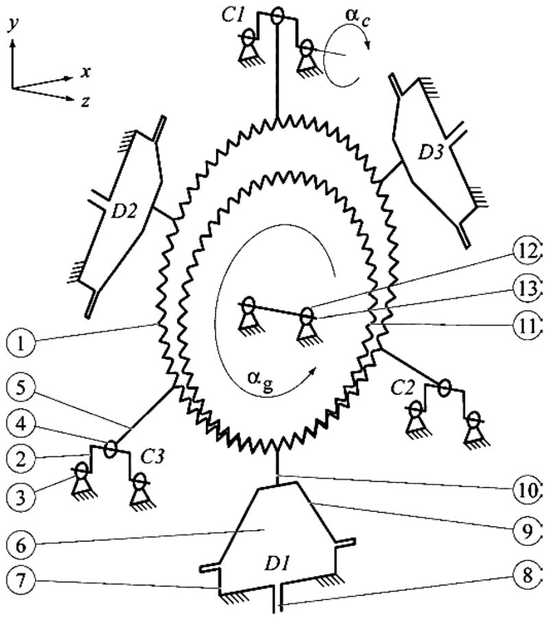
Kinematic diagram of the PneuStep motor.
Several of the components presented above form a rigid part/assembly, named “hoop-gear.” These are the internal gear ①, the three connecting rods ⑤, and the three links ⑩. The hoop-gear is connected to the cranks C1, C2, and C3 forming a triple-parallelogram (3P) mechanism: C1–C2, C2–C3, and C3–C1. This support mechanism constrains the hoop-gear to a translational-circular (TC) trajectory. The hoop-gear does not spin, but it translates on a circular path, any of its points describing a circle.
The hoop-gear is set in motion by the diaphragms D1, D2, and D3, which under pressure force the hoop-gear away from the respective cylinder. The 3P mechanism ensures that the three cranks have the same rotation and couples the motion of the three diaphragms. Directional rotation of the cranks is collected by successively pressurizing the diaphragms αc. Because the hoop-gear translates on a circle, its teeth come in and out of engagement with the spur gear, causing it to spin in the opposite direction (αg) giving the rotary output of the motor assembly. An animation is presented in Movie 1, showing similarity in motion with the hula-hoop toy of the 1950s Wham-0 Californian manufacturer, in a reversed fashion.
Functionally, the PneuStep mechanism presents two components: the motor and the gearhead. The motor is represented by the diaphragm cylinders D1–D3, the cranks C1–C3, and the hoop-gear. The rotary motion of the cranks is generated by the diaphragms even in the absence of the central spur gear, so the hypothetical output of the motor itself is the motion of the cranks. At the same time, the cranks C1–C3, the hoop-gear, and the spur gear may separately act as a transmission. If rotary motion is applied to a crank, demultiplied rotation is collected on the spur gear. With the motor, these components act as the gearhead.
This classification of components shows that the cranks and the hoop-gear assembly play a dual role in the design, both in the motor as well as the gearhead. For this, the mechanism functions as an assembly, and its gearhead is not detachable, as is the case with classic gearhead designs.
The dual-role components are part of the 3P mechanism. A single-parallelogram mechanism (1P) also presents TC motion. However, the 3P mechanism eliminates the typical singular positions of the 1P mechanism. These occur when the cranks and connecting rod are aligned. For a 3P mechanism, simultaneous alignment may never occur, making it singularity free. The payoff is that the 3P mechanism must be precisely constructed because it is overconstrained or, alternatively, a compliant mechanism could be added on one of the cranks.
Step motion is achieved by sequentially pressurizing the diaphragms. Direction is given by the order of the sequence, i.e., −z rotation for the D1-D2-D3 sequence and +z rotation for the D1-D3-D2 sequence. The motor step size is 120° of crank rotation. The common half-step operation gives a twofold step size reduction and also improves motion performance. As for electric steppers, this measure significantly reduces the incidence of resonance problems that step motor-load dynamic systems are known to experience at some speeds.
Half-step is achieved by alternating single- and dual-phase operation in a D1-D1D2-D2-D2D3-D3-D3D1 sequence, as presented in Movie 1. The motor crank output has six steps/turns.
Gear Transmission Ratio and Motor Step Size
The radius of the TC motion is given by the eccentricity e of the equal cranks (Fig. 2). The gear rolling condition is
Fig. 2.
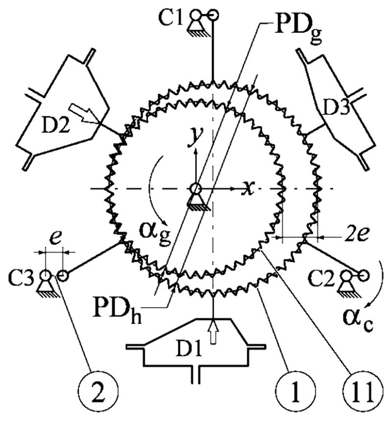
Transmission ratio and step size.
| (1) |
where PDh and PDg are the pitch diameters of the hoop and spur gear, respectively. The number of hoop (Zh) and gear (Zg) teeth relate to the same gear module M as
| (2) |
The transmission ratio of the gearhead may be expressed as
| (3) |
This shows that the transmission ratio may be as high as Zg. The gearhead reduces the size of the motor step T times.
III. Motor Design
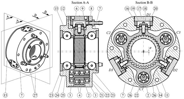
An isometric representation of the motor design and two central cross sections are presented in Fig. 3. The figure numerically identifies the elements of the kinematic diagram and pinpoints additional constructive components. The motor presents a cylindrically shaped body ⑦ closed by a cap ⑮. The diaphragm cylinders D1–D3 are built within the body. The diaphragm ⑨ is fixed with a ring ⑯ and cylinder cap ⑰ threaded in the body. The active side of the diaphragm is attached to the hoop-gear ⑭ with a screw ⑱ between the two washers ⑲, ⑳. Note that washers ⑳ are used to reduce the size of the hoop-gear ⑭ allowing its assembly in the body ⑦. The hoop-gear ⑭ is supported by the three cranks C1–C3 constructed in the form of three identical eccentric axels (Movie 2). Each axel includes a crank part ② (cylindrical with eccentric hole), a shaft ㉒, a bushing ㉑, and four bearings ③, ④. The central gear ⑪ is supported on both sides by the bearings ⑫. For compactness, the rings of these bearings are built in the body and cap parts ⑦, ⑮ and use intercalated sapphire and PTFE balls (rolling cage design).
Fig. 3.
Isometric view and two central cross sections of the motor.
The central gear ⑪ presents an internal thread ㉔ to engage a screw part (not represented), if translational output of the motor is desired. Bushings ㉓, rollers ㉔, and pins ㉕ are included for the same reason, i.e., to support and orient the screw shaft (presenting opposite flat faces for orientation, three or four faces preferable, if space allows it). With rotary output, the central bore is convenient for driving pass-through load shafts.
An important observation in the kinematics of the motor is that the motion of the diaphragms is not rectilinear. Diaphragms are attached to the hoop-gear, which exhibits TC motion. As such, the central part of the diaphragm describes circular motion. This unusual trajectory requires special design and manufacturing considerations in order to prevent premature wear and tear of the diaphragms, and allow for sustained duty cycles. The lateral displacement of the diaphragms is directly related to the eccentricity of the cranks, which should be carefully coordinated with the other design parameters.
Secondly, the design should also allow for sufficient lateral clearance of the diaphragm under its seat, so that it may freely act without stretching and wedging. Constructively, we used a custom-made diaphragm made of thin, nylon fabric coated with silicone rubber vulcanized on its cylinder face. Keeping the outer side uncoated reduces friction with the lateral walls underneath. We also observed that the weaving direction of the diaphragm fabric has significant influence on its lateral flexibility and, ultimately, its lifespan. Fabric is easier stretched in the diagonal direction of the weaving. For this reason, the fabric should be selected with higher diagonal flexibility, and the diaphragm assembled, so that its flexible direction is aligned in the direction of lateral displacement (B-B plane in Fig. 3). Diaphragm stiffness creates detent torque (torque required to spin the unpressurized motor), which is undesirable.
For MRI compatibility, the motor was constructed of the materials listed in Table I.
TABLE I.
Motor Materials
| Material | Component No. |
|---|---|
| Polyetherimide (Ultem 1000) | 2, 7, 15, 16, 19, 20, 21 |
| Delrin White | 3, 4, 23, 24 |
| Nylon 6/6 | 8, 9 |
| Peek 1000 | 17, 18 |
| GaroliteG-11 | 14, 22 |
| Polyimide | 11 |
| High-Alumina Ceramic | 25 |
| Glass | 3, 4 (bearings with Delrin rings) |
| Sapphire | 12 |
| PTFE (Teflon) | 12 (alternating) |
| White Silicone Rubber (50 Shore A) | 9 (on nylon fabric) |
Two motor sizes were constructed (Fig. 4) with overall dimensions of 70 mm × 20 mm × 25 mm, and a larger one with 85 mm × 30 mm × 30 mm outside diameter, bore, and width, respectively. The larger model has PDg = 37 mm, Zh = Zg + 2, and 6 mm/turn pitch with four starts thread. The resulting step size of the motor is 3.33° (angular) and 0.055 mm (linear).
Fig. 4.
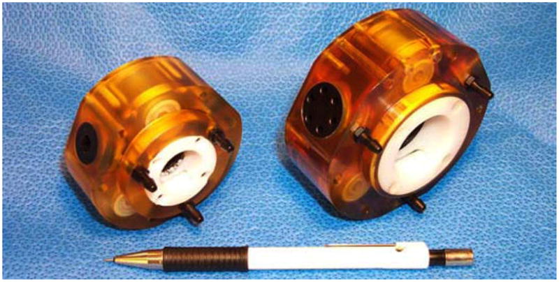
Two sizes of motor prototypes.
A challenging problem of the motor design is to minimize the size of the step while eliminating interference between the teeth of the gears. Small steps require gears with many teeth (3) nearly equal (small Zh − Zg ). This creates an interference at the top of the teeth in the region where the teeth are coming out of engagement. Typically, this is corrected with larger angles of engagement or modified tooth profiles. The latter was preferred for its lower radial forces. An interesting observation is that in these conditions the gears are “sticky,” meaning that they may not be pulled out of engagement in the radial direction. Section B-B of Fig. 3 shows that teeth detachment is restricted by the teeth on the sides of the engagement region. This fact has two implications. First, assembly should be performed axially. More interestingly, this shows that the motor could potentially be designed without the 3P-crank mechanism, but the output will become compliant through the flexibility of the diaphragms. This was used in our earlier planetary motor [10], which had no 3P and reversed in-out construction compared with the PneuStep.
IV. Pneumatic Distributor
The three ports of the motor are connected to a pneumatic distributor for generating the commutation pressure waves.
Two types have been implemented: mechanic and electronic.
1) Pneumatic rotary distributor
The design is presented in Fig. 5. The stator ㉟ presents three equally spaced radial ports P1–P3 ㊱. The pressure P and return R are coupled through the stator cap ㉚. The rotor ㉜ is mounted on the bearings ㉛, ㉝ and connected to an electric motor (not represented) on the shaft location ㉞. The rotor is constructed to generate six pressure cycles/turn. The design presents air leakage problems between the rotor and the stator. This may be addressed by using a seal or by precisely making the components, so that the air gap is minimal. We constructed the latter because it is frictionless, but manufacturing was difficult. For this reason, the electronic method presented next is preferable.
Fig. 5.
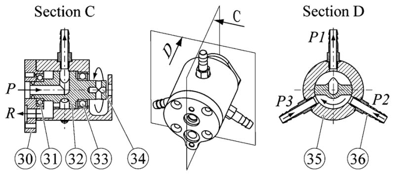
Rotary distributor.
However, the rotary distributor is very intuitive to use, and may be implemented for simple remote actuation in special cases. Remote actuation is achieved by simply connecting the ports of the motor and distributor. This may even be used with manual input. An electricity-free mechanism with 1:1 motion transfer ratio and torque amplification is implemented between the pump rotor and motor cranks. Movie 3 shows the motion of the hoop-gear in the 3P mechanism actuated by the rotary distributor. For clarity, the motor cap, spur gear, and several bearings have been removed.
2) Electronic distributor
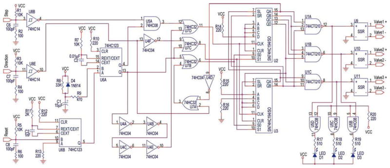
A pneumatic distributor was constructed using three electric valves mounted on a manifold. The valves are normally closed, three-way, two-position direct-acting solenoid valves. These pressurize when activated, and exhaust otherwise. A special electronic driver was designed to control the new motor with standard electric stepper-motor indexers and motion-control cards. The driver directionally cycles the activation of the valves in the desired six-step sequence, as controlled by the step and direction signals of the indexer. The circuit in Fig. 7 implements a 6-b it rotating register U2–U3 (universal shift registers) clocked by the step signal in the direction of the input. Logic gates U1 are then used to transform its state to the desired D1-D1D2-D2-D2D3-D3-D3D1 sequence, which commands the solid-state relays U9–U11 of the valves. The preset and direction logic are implemented by the monostable U6, and the gates U4, U5A, and U7. Trigger–Schmitt circuits (U8, U6 included) reduce noise sensitivity on the input signals.
Fig. 7.
PneuStep driver.
Among three types of valves tested, we found the fast-acting valve NVKF334V-5D by SMC Corporation (McMaster 61975K7) to be the best for our application, in terms of a well-balanced response time/air flow capacity. This is a 24-Vdc, 4.3-W valve with 0.2 Cv. The maximum cycling frequency is not rated, but the valve experimentally outperformed valves rated 50 Hz, and is very reliable.
The maximum cycling frequency of the valves (fmax[Hz]) gives the first limitation of the motor speed. Independent of the commutation sequencing used (full- or half-step), a valve is cycled once per crank turn. As such, the maximum stepping frequency (vmax) and the maximum speed of the output gear (ωg) are
| (4) |
In our prototypes, these maximum values are 300 steps/s, 166.6 rpm rotary output, and 16.6 mm/s linearly.
Nevertheless, the electronic distributor is preferable in most applications because it uses off-the-shelf components, is simpler, uses fewer moving components, does not leak, and outperforms the rotary distributor (Section VI). Electronic implementations also allow for dynamically changing the phase overlap of the commutation waves. This is a new research topic to optimize the timing of the half-step pressure cycles, in order to achieve maximum speed–torque performance in continuous high-speed motion. Compared with electric steppers, pneumatic commutation deals with delays and air compressibility. Hence, a detailed study of the dynamic pneumatic-mechanical system could potentially lead to improved performance of the motor.
V. Optical Encoding
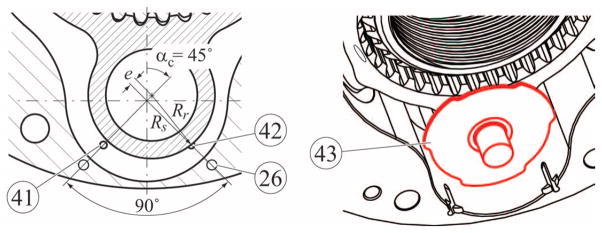
Optical encoding was added to the motor to monitor or control its motion. For compatibility with the MRI environment, we used fiber optic encoding so that all electric components are remotely located, keeping the motor electricity free. For simplicity, the existing hoop-gear part of the motor is also used for encoding in place of a traditional encoder wheel. Two fiber optic circuits are set so that the hoop-gear, in its motion, cyclically interrupts their beams generating quadrature encoded signals. Fig. 6 shows a closeup view of Section B-B in Fig. 3. In this view, the cranks have been rotated (αc = 45°) so that the fiber ends ㊶, ㊷ become visible.
Fig. 6.
Optical sensor using hoop gear (left) or 3-mark code-wheel (right).
These ends are matched with coaxially aligned fiber ends on the opposite side of the hoop-gear (fixed in the cap part ⑮). The fibers on the side of the cap are coiled back (through holes ㉖) so that the fiber optic connections ㉗ (Fig. 3) are located on the same side of the motor.
To obtain quadrature signals, the fibers have been placed 90° apart at radius Rs from the axis of the crank as
| (5) |
where Rr is the radius of the hoop-gear part over the crank bearing (Fig. 6).
A drawback of this constructive simplification is that the number of four-encoder counts per revolution is lower than the number of crank half-steps ⑥, which increases the effective step size of the motor in close-loop control. To exactly match the six motor steps, a three-mark code-wheel (㊸) was mounted on one of the cranks and used with similarly located fiber optics. This adds a simple part but improves the performance.
The ends of the fibers are connected to two D10 Expert fiber optic sensor by Banner Engineering Corporation, one for each fiber optic circuit. The digital output of these sensors is connected to the A and B encoder channels of a motion control card.
VI. Open-Loop Motion Tests
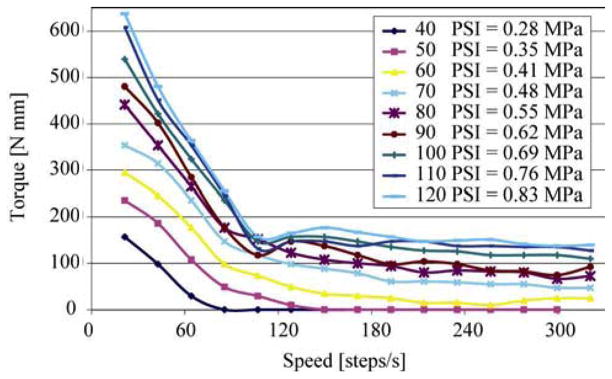
The output shaft of the motor was connected to a dynamic torque measurement stand. The motor was connected to the distributor with 1/8 in = 3.175-mm ID hoses. Experiments were performed with both distributors at various pressures and hose lengths. The diagram in Fig. 8 depicts the output torque versus speed graphs with the rotary distributor for various pressure levels, when using 3-m long hoses. The graphs show a serious deterioration of the torque capability with speed. This low-pass filter effect is given by the dynamics and compressibility of the air being pulsed faster and faster through the lines, damping the pressure waves. This is significantly influenced by the length of the hoses, which should be minimized as much as possible. Alternatively, air-piloted valves could be used, or other ways to exhaust the air on separate circuits could be implemented. The present solution was selected for its simplicity and for the restrictions of the MRI environment.
Fig. 8.
Torque versus speed with 3-m hose and rotary pump.
Each combination of pressure: hose-length: pump presents a characteristic speed above which the motor stalls, when the effective pressures acting on the diaphragms fall below internal friction levels of the motor. Fig. 9(a) shows the dependency of the stall speed on the hose length with a rotary distributor. The power of the motor is also a function of these parameters, which measured up to 37 W.
Fig. 9.
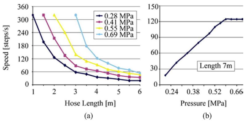
Motor stall speed versus (a) hose length with rotary pump (b) supply pressure with electronic pump and 7-m hose.
Open-loop motion tests were performed to determine stepping accuracy. These show no drift and noncumulative positioning errors, as for any stepper motors. The 99% confidence interval of the step error was ±0.84% of the angular step (3.333°). The experiments performed with the electronically controlled valve distributor show increased speed–torque performance. Fig. 9(b) shows the stall speed of the motor with 7-m hoses. The improvement may be explained by the faster opening time of the valves, which is independent of the stepping frequency allowing more time for the air-wave propagation.
VII. Closed-Loop Control and Tests
The speed–torque behavior of the PneuStep motor presented above requires particular care in implementing the control of the motor, when closed-loop operation is desired. As any step motor, when overloaded PneuStep, stalls and skips steps. Even though motion is resumed when the torque drops, the lost steps may not be acquainted for, unless an encoder is used. The built-in optical encoder may either be used as a redundant encoder in open-loop control, or for providing closed-loop feedback. In either case, with the PneuStep motor, increased torque is achieved by lowering speed. This behavior needs to be implemented in the controller.
Common stepper motion control cards use PID algorithms with various feed-forward terms and saturation functions to calculate stepping frequency and direction based on encoder feedback. When dawdling, these command higher stepping frequencies for the motor to catch up with the desired motion. For the PneuStep this is inappropriate, because the increased frequency drops the torque. To overcome this problem, we introduced a special saturation function of the command frequency, iteratively updated as
| (6) |
where the saturation s is limited to the [smin, smax] interval set below the motor stall speed [Fig. 9(b)], coefficients kmin and kmax are experimentally set, [v̄min, v̄max] is an error-transition interval, for which
| (7) |
where vd, va, and v̄ are the desired, actual, and error velocities in encoder space, respectively. In the case of the hoop-gear encoder a 6/4 conversion factor is used between the encoder and motor steps. With the 3-mark code-wheel, this is 6/12.
In normal operation, the saturation function keeps the command frequency below smax.
When significant speed errors are detected (v̄ > v̄max), the saturation is progressively reduced to gain torque. When the situation has been overcome (v̄ < v̄min), the saturation is incrementally restored. The algorithm should be tuned to activate only when incidental torque overloading occurs. Similar saturation functions are applicable to any chosen type of primary control to adapt its behavior to the particularity of the new motor.
Tests were performed connecting an eccentric weight to the motor shaft and measuring the rotation of the shaft (α) with an additional encoder. The motor is to complete a full rotation with constant velocity (125°/s) starting and stopping to rest with constant acceleration (125°/s2) from the lowest position of the eccentric (α = 0°). The graph in Fig. 10 plots the position of the shaft versus time in five experiments. For low torque values, the open-loop, regular, and modified PID controls have identical performance (Graph a). At higher torques, the PID controller fails to complete the full rotation cycle (Graph b), but the modified PID control (Graph c) recovers and completes the cycle by lowering the speed and increasing the torque.
Fig. 10.
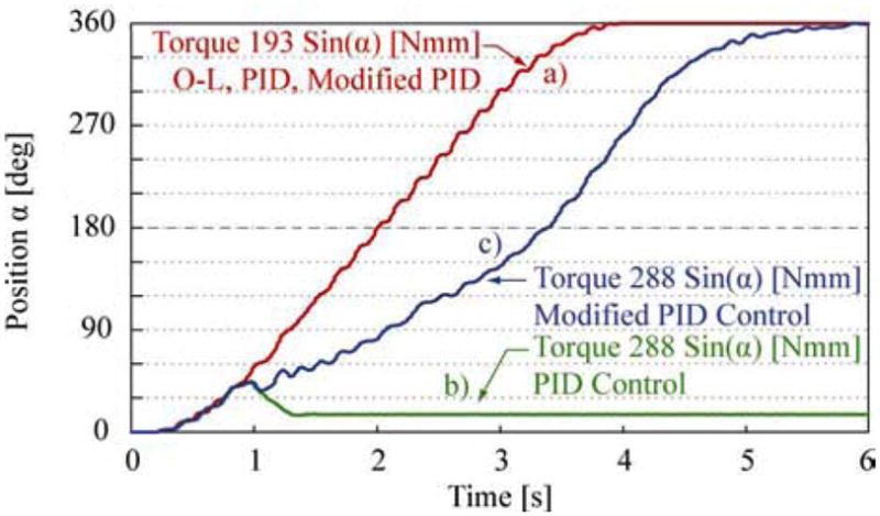
Open-loop, PID, and modified PID tests.
Step error tests were also performed with the modified PID control. As expected, these have similar results with the open-loop experiments. The 99% confidence interval of the step was 5° ± 0.028° with noncumulative errors (four count encoder used).
VIII. MRI-Compatible Robot Application
Six PneuStep motors were used to actuate the first fully MRI-compatible robot. Previously reported MRI robots had limited compatibility [12]–[14], mainly due to their piezoelectric actuation.
The robot was designed for performing transperineal percutaneous needle access of the prostate gland under direct MRI guidance. Its first application is for prostate brachytherapy [17]. The robot is positioned alongside the patient on the MRI table, as shown in Fig. 11. PneuStep performance matches the requirements of the clinical application for low speed (< 20 mm/s), high accuracy (<0.5 mm), and most importantly safety. The stepper is safer than servo-pneumatic actuation, because in case of malfunction it may only stall. Breaking a PneuStep hose, for example, may not unwind the mechanism, potentially harming the patient.
Fig. 11.
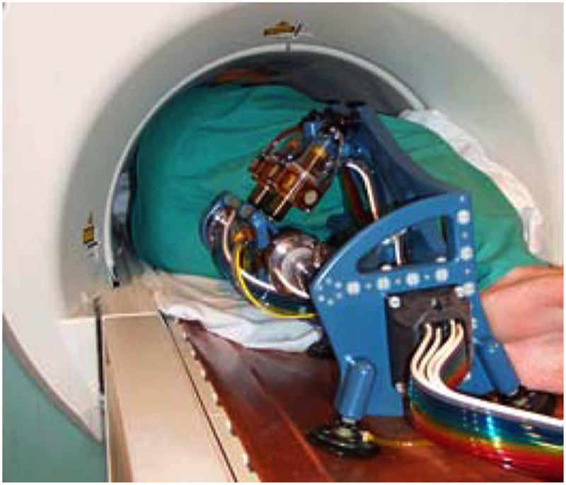
MRI-compatible robot with six PneuStep motors.
The solution of using a high-speed pneumatic motor with a high-ratio gearhead built of nonmetallic materials could potentially work for the MRI robot application. However, precision servo-pneumatic control with long hoses and the construction of the custom nonmetallic components would still be challenging. Thus, we opted to create the new motor which better suits the application for its ease, reliability, and safety.
The robot is controlled from a remotely located cabinet through 7-m hoses carrying air and fiber optics. The robot is entirely nonmagnetic and dielectric. Imager compatibility tests performed showed that the robot is unperceivable in MRI and does not interfere with the functionality of the imager, in motion or at rest. In fact, the robot is multi-imager compatible, because it is compatible with all other types of medical imaging equipment (MRI gives the most stringent constraints). Motion tests showed the mean value of the robot’s positioning repeatability to be 0.076 mm with a standard deviation of 0.035 mm, which is impressive for a “plastic” robot. The PneuStep motor was also tested in a 7-T MRI scanner (typical scanners go up to 3 T), and no problems were encountered in its operation. Animal experiments are presently underway.
IX. Discussion
The main advantage of the new motor is its simplicity of control in precise motion. This is achieved by using a step motor principle. Like for electric motors, step motion is commanded by a train of pulses (pneumatic in the PneuStep case). Proportional analog control of the pressure levels is not required. The motor takes the same steps, if pressurized with 10 or 100 PSI. Speed and torque will vary (as shown in the Fig. 8 graphs for example) but the steps are the same, independent of the pressure (within limits).
The mechanical performance of the motor allows for its use in actuating image-guided intervention robots and in other nonmedical low-speed high-precision applications. Sizably increased performance is expected to occur with dynamically optimized designs, but the main speed-limiting factor, which is the pulsing of air waves, is conceptually bound to this kinematics. For longer distances signal-amplifiers may also be considered, but PneuStep normally applies to short lines.
Hydraulic actuation of the motor is applicable for higher torques, but may not be employed to decipher the low-pass filter problem of the long hoses. Even though incompressible, the higher mass of the pulsed liquid volumes yield to higher dynamic effects, cavitation, and bubbling.
Although electric step motors have been overshadowed in motion control by servo systems, stepper motors still have several simplicity advantages. For pneumatics, moreover, servo actuation still presents significant challenges related to the response time, errors, and instability. Unlike servos, the pneumatic stepper can achieve easily controllable precise motion, which uniquely satisfies a class of applications. Also, very important in some applications is the stepper’s fault-safe behavior, preventing the motor to inadvertently spring up.
Resonance was never detected in the experiments, but is reasonable to suspect that it may occur for inertial loads at certain speeds even in open loop. As for electric motors, the use of half-step techniques should offer almost complete freedom from resonance problems.
Like any stepper, PneuStep’s drawback is the discrete positioning, but the integrated gearhead allows for trading speed in lieu of the step size. Switching to microstep control (proportional pressurizing the diaphragms) could be employed for finer fixed-point regulation, like with electrics. Again, PneuStep may only serve a certain class of applications.
X. Conclusion
This paper presents a novel motor, which fills the gap of simple and precise low-speed pneumatic actuation by introducing a step motor design. Its novelty is in the kinematic principle, which relates to the multifunction 3P mechanism. Special distributors, electronic drivers, optical encoding, and simple control adaptations are introduced to set the new motor in motion.
The motor rotation is in direct relation to the number of input pulses, and its speed is related to the frequency of the pulses. The motor holds its position under load without the aid of clutches or brakes.
It is reasonable to assume that the motor follows open-loop digital commands, if the motor is correspondingly sized to the load. Closed-loop control makes the stepper more robust to load uncertainties, and allows for using a lower size motor without loss of reliability.
The motor is not universally applicable. However, within its limitations, the motor can easily perform accurate and safe actuation unlike other pneumatic types. PneuStep is the first pneumatic stepper and the first fully MRI-compatible motor.
Supplementary Material
Acknowledgments
The contents are solely the responsibility of the author and do not necessarily represent the official views of NIH-NCI.
This work was supported by the National Cancer Institute (NCI) of the National Institutes of Health (NIH) under Grant CA88232.
Biographies

Dan Stoianovici received the Ph.D. degree in mechanical engineering from Southern Methodist University, Dallas, TX, in 1996, followed by a medical research fellowship at the Johns Hopkins Medical School, Baltimore, MD, in 1998.
Currently, he is an Associate Professor of urology and mechanical engineering at the Johns Hopkins Medical School, where he is also a Director at the URobotics Laboratory. His specialty is surgical robotics, in particular robotic hardware, with extensive hands-on experience. He has developed several robotic systems and devices, some of which are presently used in the operating room. He is the author of numerous articles, and the holder of seven patents.
Dr. Stoianovici is the New Technologies Section Editor for the Journal of Endourology, an Associate Editor for the International Journal of Medical Robotics and Computer Assisted Surgery, and a Consulting Editor for the Journal of Robotic Surgery. He is the Co-president of the Engineering and Urology Society.

Alexandru Patriciu (S’00–M’04) received the B.S. and M.S. degrees in computer science from the University of Craiova, Craiova, Romania, in 1994 and 1995, respectively, and the Ph.D. degree in mechanical engineering from the Johns Hopkins University, Baltimore, MD, in 2004.
From 1994 to 1996, he was with the Institute for Computers, Romania. From 1996 to 1999, he was with the Computer Science Department, University of Craiova. From 2004 to 2006, he was a Postdoctoral Fellow in urology at the Johns Hopkins University, under an American Foundation for Urological Diseases fellowship. Currently, he is a Senior Scientist at the National Institutes of Health (NIH), Bestheda, MD. His research interests include medical robotics and image-guided robotic-assisted medical interventions.

Doru Petrisor received the M.S. degree in mechanical engineering from the University of Craiova, Craiova, Romania, in 1988, and the Ph.D. degree from the University of Petrosani, Petrosani, Romania, in 2002, followed by a research fellowship in urology at the Johns Hopkins University, Baltimore, MD.
His specialty is cartesian numerical control (CNC) manufacturing and design of surgical robotics. From 1991 to 1994, he was an Assistant Professor at the University of Craiova, where he became a Lecturer in 1994. Since 2002, he has been with the URobotics Research Group at Johns Hopkins University.

Dumitru Mazilu (M’02) received the M.S. and Ph.D. degrees in mechanical engineering from the University of Craiova, Craiova, Romania, in 1984 and 1998, respectively.
From 1990 to 1999, he was with the Mechanical Engineering Department, University of Craiova. From 1999 to 2002, he was a Postdoctoral Research Fellow in the Urology Department at Johns Hopkins University, Baltimore, MD, under an American Foundation for Urological Diseases fellowship, where he became a Research Associate in 2003. Since 2006, he has been a Research Scientist at the National Institutes of Health (NIH), Bestheda, MD. His primary current research area is design and manufacturing of medical robotics.

Louis Kavoussi is currently the Chairman of Urology at the North Shore-Long Island Jewish Health System, and also a Professor of urology with New York University School of Medicine, New York. Until 2005, he was with the Urology Department at Johns Hopkins University, Baltimore, MD. He has pioneered several new operative techniques including the laparoscopic nephrectomy for cancer and live renal transplant. He was also a part of the team that performed the first laparoscopic prostatectomy. He is considered an expert in urological diseases, as evidenced through his multiple national awards and over 300 publications.
He is the Editor of Campbell’s Urology, which is the specialty’s leading test, as well as the Editor of the American Urological Association Update Series, a monthly publication reviewing the state-of-the-art in urology.
Footnotes
Dynatork Air Motors, Hertford, U.K., http://www.dynatork.co.uk/
This paper has supplementary multimedia material available at http://ieeexplore.org, provided by the author. The material includes three short mpg movies. movie1.mpg shows an animation of the kinematic diagram of the PneuStep motor. movie2.mpg is a CAD rendered animation of the hoop and central gears on the 3P mechanism. movie3.mpg is an “open hood” movie of the motor in motion connected to the mechanical distributor. The movies are MPG1 format and work with various players including Windows Media Player and Quick Time Player applications.
Contributor Information
Dan Stoianovici, Email: dss@jhu.edu.
Alexandru Patriciu, Email: patriciua@cc.nih.gov.
Doru Petrisor, Email: doru@urology.jhu.edu.
Dumitru Mazilu, Email: mazilud@nhlbi.nih.gov.
Louis Kavoussi, Email: kavoussi@nshs.edu.
References
- 1.Choi HS, Han CS, Lee KY, Lee SH. Development of hybrid robot for construction works with pneumatic actuator. Autom Construc. 2005;14:452–459. [Google Scholar]
- 2.Hagglund T. A friction compensator for pneumatic control valves. J Process Control. 2002;12:897–904. [Google Scholar]
- 3.Bendov D, Salcudean SE. A force-controlled pneumatic actuator. IEEE Trans Robot Autom. 1995 Dec;11(6):906–911. [Google Scholar]
- 4.Butefisch S, Seidemann V, Buttgenbach S. Novel micro-pneumatic actuator for MEMS. Sens Actuators A, Phys. 2002;97–98:638–645. [Google Scholar]
- 5.vanVarseveld RB, Bone GM. Accurate position control of a pneumatic actuator using on/off solenoid valves. IEEE/ASME Trans Mechatronics. 1997 Sep;2(3):195–204. [Google Scholar]
- 6.Shen TL, Tamura K, Kaminaga H, Henmi N, Nakazawa T. Robust nonlinear control of parametric uncertain systems with unknown friction and its application to a pneumatic control valve. ASME J Dyn Syst Meas Control. 2000;122:257–262. [Google Scholar]
- 7.Richer E, Hurmuzlu Y. A high performance pneumatic force actuator system: Part I-Nonlinear mathematical model. ASME J Dyn Syst Meas Control. 2000;122:416–425. [Google Scholar]
- 8.Richer E, Hurmuzlu Y. A high performance pneumatic force actuator system: Part II-Nonlinear controller design. ASME J Dyn Syst Meas Control. 2000;122:426–434. [Google Scholar]
- 9.Renn JC, Liao CM. A study on the speed control performance of a servo-pneumatic motor and the application to pneumatic tools. Int J Adv Manuf Technol. 2004;23:572–576. [Google Scholar]
- 10.Stoianovici D. Multi-imager compatible actuation principles in surgical robotics. Int J Med Robot Comput Assisted Surg. 2005;1:86–100. doi: 10.1002/rcs.19. Online. Available: http://urology.jhu.edu/urobotics/pub/2005-stoianovici-MRCASJ.pdf. [DOI] [PMC free article] [PubMed]
- 11.Cissell T, Doerschuk D, Koester K, Reed G. Pneumatic stepper motor actuator. 5 060 539. Columbus, OH: US Patent. 1991
- 12.Masamune K, Kobayashi E, Masutani Y, Suzuki M, Dohi T, Iseki H, Takakura K. Development of an MRI-compatible needle insertion manipulator for stereotactic neurosurgery. J Img Guided Surg. 1995;1:242–248. doi: 10.1002/(SICI)1522-712X(1995)1:4<242::AID-IGS7>3.0.CO;2-A. [DOI] [PubMed] [Google Scholar]
- 13.Chinzei K, Miller K. Towards MRI guided surgical manipulator. Med Sci Monit. 2001;7:153–163. [PubMed] [Google Scholar]
- 14.Hempel E, Fischer H, Gumb L, Hohn T, Krause H, Voges U, Breitwieser H, Gutmann B, Durke J, Bock M, Melzer A. An MRI-compatible surgical robot for precise radiological interventions. Comput Aided Surg. 2003;8:180–191. doi: 10.3109/10929080309146052. [DOI] [PubMed] [Google Scholar]
- 15.Louw DF, Fielding T, McBeth PB, Gregoris D, Newhook P, Sutherland GR. Surgical robotics: A review and neurosurgical prototype development. Neurosurgery. 2004;54:525–536. doi: 10.1227/01.neu.0000108638.05274.e9. [DOI] [PubMed] [Google Scholar]
- 16.Neuerburg J, Adam G, Bucker A, Zilkens KW, Schmitz Rode T, Katterbach FJ, Klosterhalfen B, Rasmussen E, van Vaals JJ, Gunther RW. MR-guided bone biopsy performed with a new coaxial drill system. Rofo-Fortschr Rontg. 1998;169:515–520. doi: 10.1055/s-2007-1015330. [DOI] [PubMed] [Google Scholar]
- 17.Muntener M, Patriciu A, Petrisor D, Mazilu D, Kavoussi L, Cleary K, Stoianovici D. MRI guided robotic system for fully automated brachytherapy seed placement. Urology. doi: 10.1016/j.urology.2006.08.1089. to be published. [DOI] [PMC free article] [PubMed] [Google Scholar]
Associated Data
This section collects any data citations, data availability statements, or supplementary materials included in this article.


