Abstract
This paper reviews our work on the application of ultrafast pulsed laser micro∕nanoprocessing for the three-dimensional (3D) biomimetic modification of materials surfaces. It is shown that the artificial surfaces obtained by femtosecond-laser processing of Si in reactive gas atmosphere exhibit roughness at both micro- and nanoscales that mimics the hierarchical morphology of natural surfaces. Along with the spatial control of the topology, defining surface chemistry provides materials exhibiting notable wetting characteristics which are potentially useful for open microfluidic applications. Depending on the functional coating deposited on the laser patterned 3D structures, we can achieve artificial surfaces that are (a) of extremely low surface energy, thus water-repellent and self-cleaned, and (b) responsive, i.e., showing the ability to change their surface energy in response to different external stimuli such as light, electric field, and pH. Moreover, the behavior of different kinds of cells cultured on laser engineered substrates of various wettabilities was investigated. Experiments showed that it is possible to preferentially tune cell adhesion and growth through choosing proper combinations of surface topography and chemistry. It is concluded that the laser textured 3D micro∕nano-Si surfaces with controllability of roughness ratio and surface chemistry can advantageously serve as a novel means to elucidate the 3D cell-scaffold interactions for tissue engineering applications.
INTRODUCTION
Nature offers a diverse wealth of functional surfaces, whose properties are unmatched in today’s artificial materials.1 There is a growing body of information describing natural materials with sophisticated design strategies, which lend the organisms and plants superior mechanical, self-cleaning, optical, adhesive, actuation, sensing, and responsive capabilities. Such adaptive and responsive self-assembly is provided by means of a hierarchical self-organization and optimization of the biological material at each level of hierarchy to yield outstanding performance. Indeed, well-ordered, multiscale structures with dimensions of features ranging from the macro- to the nanoscale are extremely common in natural materials.
Learning from nature will give us important inspiration to develop new techniques and methodologies to construct artificial advanced materials. This approach of designing novel materials is called “biomimetics” and involves the transformation of the ideas, concepts, and underlying principles developed by nature into manmade technology. Although biomimetics has emerged in the 1960s, it has been developing rapidly in the past decade due to advancements in nano- and biotechnologies. Currently, a large area of biomimetic research deals with functional micro- and nanostructures for nanoscale devices, water repellence, self-cleaning, drag reduction in fluid flow, energy conversion and conservation, high adhesion, aerodynamic lift, materials and fibers with high mechanical strength, antireflection, structural coloration, thermal insulation, self-healing, responsiveness, and sensory aid mechanisms.1, 2 All these exceptional functionalities are excellently demonstrated by natural systems and are based on a variety of ingenious designs of biological surfaces. Similar to all natural materials, biological surfaces exhibit hierarchical morphology at the micro- and the nanoscales while the desired functionality is achieved through a tailored synergy of surface roughness and chemistry.
This paper will review our effort on the fabrication and functionalization of biomimetic artificial micro- and nanotextured surfaces for novel applications, based on ultrafast laser structuring of materials. Following nature’s strategy, we have developed a two-step approach; in the first step the morphological characteristics were controlled through ultrafast laser micro∕nanostructuring, whereas in the second step the surface chemistry is tuned depending on the desired functionality. Emphasis will be placed on the methodologies employed appropriate for microfluidics and tissue engineering applications for which there is an increasing demand over the previous years. In both cases, the significance of dual-scale biomimetic morphology will be indicated. Besides presenting recent advances achieved, it will also delineate existing limitations and discuss emerging possibilities and future prospects.
BIOMIMETIC FABRICATION OF HIERARCHICAL SURFACES
Laser based micro∕nanostructuring of solids
Several different physical and chemical patterning approaches have been employed for structuring surfaces, so as to tailor their morphology, including photolithography,3 templated electrochemical deposition,4 plasma treatments,5 electron-beam lithography,6 and selective growth of carbon nanotubes.7 Ultrafast lasers are increasingly proving to be a promising tool for three-dimensional (3D) micro- and submicron texturing of materials surfaces. One of the most useful properties of ultrafast laser induced modification is the limited size of the affected volume.8 Ablation with laser pulses is induced by optical breakdown, which generates plasma near the laser focus. Because the plasma recombines before thermal diffusion, shock wave propagation, and cavitation set in, ablation of the substrate is confined, at least initially, to a small volume. Although the intensity required to initiate breakdown is fairly high, the short duration of the pulse allows the threshold intensity to be achieved with a lower intensity. The combination of localized excitation and low threshold fluence can greatly reduce the extent of collateral damage to surrounding areas, so that the size of the affected material can be microscopic—very close to the diffraction-limited focusing volume. As a consequence, three-dimensional structures constructed using nonlinear absorption laser structuring techniques provide excellent control over micro- and submicron scales. Additional advantages of laser structuring include its very high fabrication rate, noncontact interaction, applicability to many types of materials, such as ceramics, metals, and polymers, and reproducibility. It can be used to shape materials both laterally as well as into the depth of the material, hence allowing the manufacture of structures with complex geometries including 3D shapes or structures with varying wall shapes and etch depths, and various aspect ratios on the same substrate, which represents a great difficulty for planar clean-room techniques. Furthermore, lasers can be easily incorporated to computer-assisted fabrication systems for complex and customized 3D matrix structure design and manufacture. Such systems gave rise to a versatile class of 3D structures production techniques, which are laser-based solid-free-form (SFF) fabrication techniques. The SFF is a rapid prototyping technique that allows for control over macroscopic properties, such as scaffold shape and microscopic internal architecture.
Microstructuring by femtosecond,9 picosecond,10 and nanosecond lasers11 in specific reactive environments is specifically attractive, because it leads to the formation of high-aspect ratio microconical structures on solid surfaces.12, 13, 14 Their easy, maskless fabrication, in combination with their improved properties as compared to untreated surfaces, constitutes them particularly attractive for a wide range of applications, including electronic,9, 15 optical,16, 17 and chemical analysis.18 Special interest has been shown in the unique optical properties microstructured Si exhibits, i.e., increased absorptance throughout a wide spectral range, for possible applications in photodetector and solar cell technology. This property is a consequence of the highly rough morphology and chemical modification induced by laser irradiation in the presence of the reactive gas. Owing to this unique optical property, microstructured Si is often called “black Si.”
This section deals with the formation of structures on Si and metallic surfaces, both at the micrometer and the nanometer length-scale, upon laser irradiation with near infrared femtosecond-laser pulses in reactive gas atmosphere. The processes by which femtosecond-laser pulses interact with silicon differ greatly from those longer pulses. The modification of solids with femtosecond pulses is not yet well-understood, but it is considered that nonthermal, ultrafast phase transformations can occur on a timescale much faster than thermal processes. It will be shown that the interaction of femtosecond-laser irradiation with conductive solids leads to the formation of microconical structures on its surface, whose characteristics can be controlled by laser parameters. Emphasis will be given on the advantage of femtosecond-laser structuring under reactive gas which leads to controlled dual-scale rough surfaces comprising microconical structures decorated with nanometer sized protrusions. It is concluded that femtosecond-laser irradiation can lead to simultaneous structuring of solid substrates at two length scales through a simple one-step production process, which is highly desirable for applications.
Details on the experimental procedure followed for the femtosecond-laser induced surface structuring of Si can be found elsewhere.10, 12, 13 Briefly, single crystal Si wafers were subjected to laser irradiation in a vacuum chamber evacuated down to a residual pressure of 10−2 mbar. A constant SF6 pressure of 500 Torr was maintained during the process through a precision microvalve system. The irradiating laser source was constituted by a regenerative amplified Ti:sapphire (λ=800 nm) delivering 150 fs pulses at a repetition rate of 1 kHz. The sample was mounted on a high-precision X-Y translation stage normal to the incident laser beam. A mechanical shutter was synchronized to the translation stages, exposing any given spot on the Si surface to an average of 500 pulses. Each microstructured surface was fabricated at constant fluence ranging from 0.34 to 2.25 J∕cm2. After laser irradiation, the microstructured surfaces were cleaned with ultrasonic baths of trichloroethylene, followed by acetone and ethanol, followed by a 10% hydrofluoric acid (HF) aqueous treatment in order to remove the oxide grown on the treated surface. Then each surface was morphologically characterized by field emission scanning electron microscopy (SEM). An image processing algorithm was implemented in order to obtain quantitative information concerning the topological characteristics of the formed structures, i.e., spikes density, profile, height, and surface area from top, side-view, and cross-sectional SEM pictures of the structured regions.
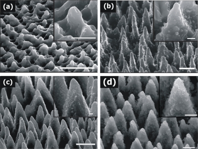
The textured Si surfaces realized by employing the same number of laser pulses at different irradiation fluences are presented in Fig. 1. Increasing the incident energy per unit area causes remarkable changes in the structure’s shape, dimension, and density. At low fluences, laser heating induces melting of the surface producing a rippled landscape, with structures not completely physically separated. Upon increasing fluence, conical morphology is promoted on the surface, with spikes becoming more pronounced and spatially separated. In the low-fluence regime, the average interspike spacing, base diameter, and height increase with laser fluence, whereas their density decreases. For large fluence values (above ∼1.0 J∕cm2), the spikes density reaches a plateau, while the height stabilizes around 10 μm. Besides directly affecting the micrometer-scale surface topology, increasing fluence is also crucial to induce a more pronounced submicrometer decoration on the spikes walls. In particular, the protrusions with size from tens to a few hundreds of nanometers, which provide the double length-scale pattern on the Si surface, become more evident as the laser fluence increases (Fig. 1). The micrometer-scale features generated by the spikes landscape together with the nanoscale features generated by the surface prongs on the cones result into a significant increase of the overall roughness. It should be outlined that the reactive gas plays a distinct role in the fabrication process, since it determines the sharpness of the microstructures obtained. Furthermore, the formation of second-length scale roughness on the cones surface becomes more pronounced with increasing ambient gas pressure. On the contrary, the Si structures fabricated in vacuum are blunt and irregular.
Figure 1.
Side-view scanning electron microscope image (45°) of Si surfaces structured by 800 nm, 180 fs irradiation at different laser fluences. (a) 0.37 J∕cm2, (b) 0.78 J∕cm2, (c) 1.56 J∕cm2, and (d) 2.47 J∕cm2 (scale bar of 5 μm). Higher magnifications of the obtained structures are shown in the corresponding insets (scale bar of 1 μm).
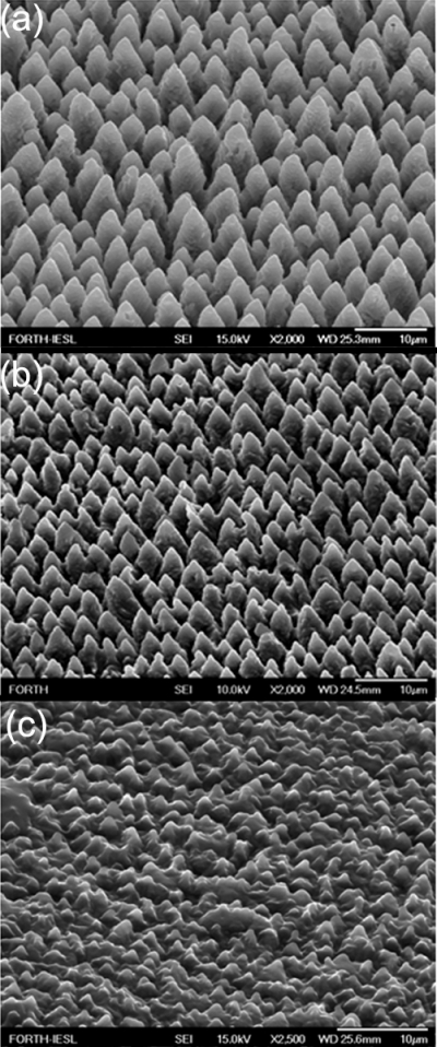
The 3D microstructures obtained in Si can be transferred to various types of polymeric and∕or biopolymeric materials through replication molding techniques. Figure 2 shows examples of microstructures replicated in a photocurable (ORMOCER) and biodegradable (PLGA) polymer, respectively. Replication, i.e., the copying of 3D surface microstructures from a master sample mold into a formable material, may offer an important fabrication technology for certain types of applications. This technology features limited processing steps and prompts lower production costs for mass production, since many copies can be made from a single mold.
Figure 2.
Side scanning electron microscope view (45°) of an ultrafast laser-structured initial Si surface (a), the same surface replicated on a photopolymer (ORMOCER) (b) and on a biodegradable polymer (PLGA) (c).
Functionalization
Along with the spatial control of the surface topology, defining surface chemistry can provide new insights into fundamental aspects of liquid manipulation in microfluidics and cell response. The functionalization approach presented in the following is to attach passive and∕or responsive chemical materials onto the structured surfaces, by appropriate immobilization processes that will lead to a well-defined surface chemistry. Such coatings can potentially induce large differences in the surface energy, while keeping the same morphology. Furthermore, controlled deposition of functional responsive synthetic materials can reversibly switch the surface energy and thus wettability in response to appropriate external stimuli including light, electric field, pH, temperature salt concentration, etc. The surfaces attained, with the capacity to exquisitely control micro∕nanotopography and chemistry, will enable a multiparametric assessment of the various tools to tune surface energy with far-reaching implications for microfluidics and tissue engineering applications.
TAILORING THE WETTING RESPONSE FOR MICROFLUIDIC APPLICATIONS
Controllable manipulation of liquids has been the subject of considerable amount of scientific research for the development of microfluidic and lab-on-chip devices. In search of ways to efficiently drive a drop to specific sites in order to perform discrete functions such as mixing, analysis, reaction, and storage, different approaches have been implemented based on the control over interfacial energy and thus wettability. Indeed, employing surface energy gradients to manipulate liquids has been a common approach for liquid actuation in microfluidics. Actuations using Maragoni effects, electrowetting effects, stimuli-responsive surface energy changes, and those due to wettability gradient created by varying chemical composition have been reported in the past.
Advances in microfluidic systems design can be achieved via adapting the special wettabilities and behaviors of natural materials in future biomimetic microfluidic systems.19, 20 Nature teaches us that special wetting characteristics can be achieved through the synergy of micro- and nanoroughness and surface chemistry. In the past few years, there have been remarkable advances in the understanding of wetting properties of rough surfaces. This knowledge opened up the possibility of employing roughness gradients as a new additional control variable that can be exploited to attain liquid manipulation. Accordingly, there is an increasing research interest to realize open microfluidic systems based on the synergy of roughness and chemistry to manipulate liquids.21 In most cases, the role of biomimetic hierarchical roughness is proved to be crucial. Depending on the desired functionality, a wide spectrum of hierarchical morphologies has been obtained and combined with various functional chemistries, giving rise to the first biomimetic microfluidic devices.21, 22, 23 In this context, manufacturing schemes enabling the controlled and reproducible structuring of materials at micro- and nanoscales combined with surface functionalization methods are very desirable.
Direct laser micro∕nanostructuring is a mature and versatile technique that presents some key benefits over other more established microfabrication techniques for open microfluidic applications.24 There are several recent reports on the implementation of ultrafast laser direct writing for liquid manipulation via altering surface wettability. Using direct high-intensity femtosecond-laser surface structuring, Guo et al. created a novel surface pattern that transforms regular Si25 or metallic surfaces26 to superwicking. Due to the superwicking effect, the structured surface renders liquids to sprint vertically uphill against the gravity over an extended distance. Furthermore, microfluidic open channels with either hydrophilic or hydrophobic surfaces have been fabricated using femtosecond-laser direct ablation of poly(methyl methacrylate) (PMMA) at various fluences.27 Zhang et al.28 reported special wetting characteristics of Si surfaces patterned by femtosecond-laser micromachining, including high adhesive force and anisotropic wettability. Finally, femtosecond-laser modification followed by HF treatment was proved to be a powerful method for fabricating 3D microfluidic structures inside photosensitive glass.29, 30
Water-repellent and self-cleaning properties
Control over the wettability of solids and manufacturing of functional surfaces with special hydrophobic and self-cleaning properties has aroused great interest because of its significance for a vast range of applications in daily life, industry, and agriculture. Manufactured superhydrophobic and water-repellent surfaces have been demonstrated for a wide range of applications, such as self-cleaning surfaces, biological scaffolds, microfluidics, lab-on-chip devices, coatings for automotive and aerospace vehicles, and textiles.31, 32, 33 Mimicking nature has been a central strategy in this field, since biological species have many extraordinary wetting properties. One example is the lotus plant, Nelumbo nucifera (the sacred lotus). Revered as a symbol of purity in several ancient cultures, its leaves stay clean even though it grows in muddy lakes and ponds. The leaf is so water-repellent that a droplet touching its surface instantly acquires a spherical shape, and even slight tilting causes it to roll off the leaf; this was coined the “lotus effect.”34 Similar behavior has been observed on other biological surfaces like the wings of Cicada orni or Rhinotermitidae insects.
A water-repellent surface exhibits certain remarkable wetting characteristics originating from very high contact angles (CAs), in excess of 150°, and very small values of contact angle hysteresis (less than 5°).35 Droplets roll down these surfaces at a speed faster than that of a solid sphere rolling under gravity.36 They can fully bounce after impacting the surface37, 38 whereas the time of contact of an impacting droplet with the surface is independent of its velocity.38 In order to create the lotus effect, it is important to understand how nature generates this property. SEM images of water-repellent biosurfaces have revealed large structural diversity, with the common characteristic of roughness over two different length scales. In particular, the lotus leaf surface is covered with micrometer-sized papillae decorated with nanometer branchlike protrusions.39, 40 Apart from this unique hierarchical morphology, the surface chemistry originates from epidermal cells of waxy hydrophobic crystals. The roughness of the hydrophobic papillae reduces the contact area between the surface and a liquid drop, with droplets residing only on the tips of the epicuticular wax crystals on the top of papillose epidermal cells. Water repellency stems from the synergy of dual-length-scale roughness and hydrophobic surface chemistry.41 Thus, researchers are seeking simple micro- and nanomanufacturing methods that enable the reproducible construction of double length-scale topologies.
In Sec. 2A we have presented a methodology to prepare artificial surfaces that possess hierarchical micro- and nanostructures. They are prepared with a simple one-step production process using ultrafast (femtosecond) laser irradiation of a silicon surface under a reactive gas atmosphere. The height of the microscale conical features along with the number of nanoscale protrusions decorating the cones increases with laser fluence, resulting in a significant increase of the overall roughness. Accordingly, in the high-fluence regime, the nanometer scale roughness becomes increasingly enhanced. Further reduction of the surface free energy and thus increase in hydrophobicity is achieved by coating the dual-rough patterned surfaces by organosilane monolayers. Dimethyldichlorosilane (DMDCS) is chosen among other hydrophobic silanes due to its lower tendency to polymerize on Si surfaces, and its excellent stability, allowing it to maintain its hydrophobic properties for long time and wide temperature range.42 The CA measured on the DMDCS-coated flat Si was 104°, close to that reported for total monolayer coverage.43 Spectroscopic ellipsometry measurements on the flat region of the samples show that the average thickness of the silane coating is about 2.5 nm, in agreement with other studies on similar coatings.44 Atomic force microscopy images of silane-coated regions on the flat part of Si show a relatively homogeneous deposition of molecules over the entire area. The rms roughness is ∼1 nm indicating dense, void-free coverage.
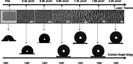
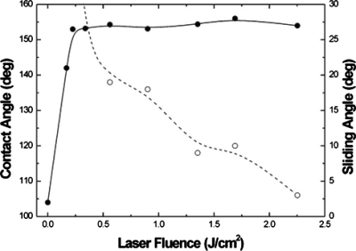
Figure 3 shows the snapshots of a water droplet lying on a DMDCS terminated flat and microstructured Si surfaces as a function of laser fluence.45 The corresponding evolution of the CAs and sliding angles measured on the laser-structured surfaces are shown in Fig. 4. Water droplets leave the structured area at tilt angles lower than 10° for samples treated at fluences higher than ∼1.5 J∕cm2. Interestingly, these high-fluence samples exhibit the most pronounced second-length-scale surface roughness. Samples in the midfluence range (0.7–1.5 J∕cm2) do not meet both criteria for superhydrophobicity; they exhibit high sliding angles although they show similar contact angle to their high-fluence counterparts. At fluences lower than 0.7 J∕cm2, water drops remain pinned on these surfaces, at the highest sliding angles utilized. Evidently, contact angle hysteresis is a very important parameter when droplet motion on a surface is considered. Motion initiation, at very low inclination angles (5°) on the high-fluence superhydrophobic surfaces, is translated into a small gravitational force required to initiate motion. In other words, the friction between the droplet and the structured surface is accordingly low. Low frictional motion is a key feature behind the unique lotus self-cleaning property and it is therefore desirable in any corresponding application, as it provides for efficient motion of water droplets even when long travel distances are necessary.
Figure 3.
Side scanning electron microscope view (45°) of silicon surfaces structured by femtosecond irradiation at different laser fluencies. The corresponding photographs of water droplets placed on the surfaces coated with hydrophobic silane monolayers are also shown.
Figure 4.
Static contact angle (●) and sliding angle (○) measurements of a water drop on structured Si surfaces plotted as a function of laser fluence. For fluences below 0.5 J∕cm2, the sliding angles are higher than the 30° limit of our measurement setup. The lines are guides to the eye. Reproduced with permission from V. Zorba et al., Appl. Phys. A: Mater. Sci. Process. 93, 819 (2008). Copyright 2008. Springer.
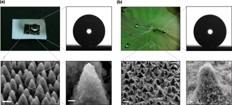
The artificial surfaces prepared at high fluences can quantitatively mimic both the structure and the water-repellent characteristics of the natural lotus leaf. Images of a water droplet lying on the artificial surface are shown in Fig. 5a, which can be directly compared to those of a droplet lying on the surface of a lotus leaf shown in Fig. 5b. The static CA of water on the artificial surface is measured as 154±1° with a contact angle hysteresis of 5±2°, whereas those on the lotus leaf as 153±1° and 4±2°, respectively. Figure 5b shows the SEM images of the surface of the lotus leaf, which comprises randomly distributed almost-hemispherically topped papillae with sizes of 5–10 mm (height to basal radius aspect ratio of ∼1) decorated with branch like protrusions with size of about 150 nm [Fig. 2d]; these observations are in agreement with earlier reports.39, 40 Figure 5a shows the SEM micrographs of the most water-repellent artificial surface, which exhibits the highest contact angle and the lowest hysteresis among the different surfaces obtained by varying the irradiation parameters. Its morphology looks very similar to that of the lotus leaf [Fig. 5b] consisting of microscale conical features decorated with nanoscale protrusions. The protrusions in this case have conical or pyramidal asperities with average size of ∼10 μm and aspect ratio of ∼4. Nanostructures of sizes up to a few hundred nanometers are clearly seen on the slopes of the protrusions [Fig. 5d]. Thus, the femtosecond-laser irradiation under reactive SF6 atmosphere was indeed able to produce a surface that mimics the structural features of the lotus leaves as well as their water CA properties.
Figure 5.
(a) Top left: picture of a water droplet on an artificial structured silicon surface (dark area). Top right: static contact angle measurement of a water droplet of 0.78 mm radius on that surface; the contact angle is 154°±1°. Bottom left: SEM image of the artificial surface comprising protrusions with conical or pyramidal asperities (scale bar 5 μm). Bottom right: high magnification SEM image of a single protrusion depicting nanostructures of sizes up to few hundred nanometers on the slopes of the protrusions (scale bar 1 μm). The surface was structured in the presence of 500 Torr SF6 at a laser fluence of 2.47 J∕cm2 with an average of 500 pulses. (b) Top left: picture of water droplets on a Nelumbo nucifera (lotus) leaf. Top right: static contact angle measurement of a water droplet of 0.78 mm radius on the lotus leaf surface; the contact angle is 153°±1°. Bottom left: SEM image of the leaf surface (scale bar 5 μm). Bottom right: high magnification SEM image of a single papillose depicting branch like protrusions with a size of about 150 nm (scale bar 1 μm). Reproduced with permission from V. Zorba et al., Adv. Mater. (Weinheim, Ger.) 20, 4049 (2008). Copyright 2008. Wiley-VCH Verlag GmbH & Co. KGaA.
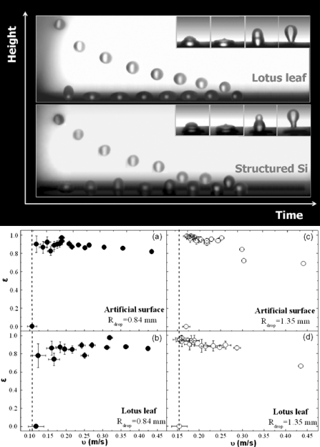
Additional quantitative information on the water repellence properties of a surface can be determined through studying the dynamic behavior of a water droplet impinging on it.32 The upper part of Fig. 6 presents a selected sequence of snapshots of a water drop impacting on the laser-structured silanized surface in comparison to a lotus leaf surface. The minima and maxima of the drop trajectory are shown here as a function of time. The drop’s shape changes significantly during impact (insets) as its kinetic energy transforms into stored energy. Despite the strong deformation of the liquid, both surfaces are so water-repellent that the drop bounces back numerous times. On the contrary, no rebound is observed when the drop impacts on the flat (unstructured) region of a silanized silicon surface.
Figure 6.
(Top) Selected snapshots of a water drop impinging on the surface of the lotus leaf and the artificial laser-structured silanized silicon surface. The minima and maxima of the drop trajectory are shown here as a function of time. The drop in both cases bounces back numerous times before it comes to rest on the surfaces after ∼400 ms. The drop is significantly deformed during each impact; the dynamics of this process is shown at the insets. (Bottom) Restitution coefficient ε=υ′∕υ, where υ′ is the center of mass velocity right after the impact and υ that right before the impact, as a function of the impact velocity υ for an artificial silane-coated structured silicon surface [(a) and (c)] and a lotus leaf surface [(b) and (d)] for two different sizes of falling water droplets with radii R of 0.84 mm [(a) and (b)] and 1.35 mm [(c) and (d)]. The dashed lines signify the threshold velocities of 0.11 and 0.17 m∕s for the artificial surfaces for the two sizes of water droplets, respectively.
The elasticity of the collisions observed on both the artificial laser-structured surface and that of the natural lotus leaf is remarkable, indicating a high degree of repellency. A direct measure of this elasticity is the restitution coefficient, ε=υ′∕υ, defined as the ratio of the center of mass velocity just after impact υ′ to that just before impact υ. This coefficient was deduced from the respective heights the droplet reaches after impact and is shown in Fig. 6 as a function of the impact velocity υ. The highest elasticity is observed at intermediate velocities where the restitution coefficient is found to exceed 0.90, denoting that 90% of the drop’s initial kinetic energy is restored upon impact. Its value matches that of the lotus leaf and, to our knowledge, is among the highest ever reported.
In summary, we have shown that femtosecond-laser structuring under reactive gas atmosphere can produce a surface that mimics both qualitatively and quantitatively the structural features of the lotus leaves as well as their water repellence performance. To our knowledge, this is the first time such a direct comparison of performance is made and it clearly demonstrates the possibility of designing highly efficient biomimetic water-repellent surfaces. This opens up the possibility for fabrication of water-repellent surfaces in other types of materials, such as metals, polymers, as well as optically transparent materials, thus creating opportunities for various exciting applications. These include self-cleaning, water-resistant surfaces, low-frictional underwater and anti-ice coatings, as well as controlled deposition and guiding of water droplets and biofluids in biomicrofluidics.
Stimuli-responsive∕smart surfaces
The understanding and fabrication of functional and responsive surfaces with wetting properties that can be controllably altered on demand has attracted the interest of the scientific community due to their wide variety of potential applications, including micro∕nanofluidics,46 “lab-on-chip” devices,47 controllable drug delivery,48 enzyme immobilization,49 bioseparation,50 cell sheet engineering,51 sensor development,52 energy and green engineering,53 antifouling,54 and self-cleaning surfaces. These surfaces are able to reversibly switch55 their hydrophobicity∕hydrophilicity in response to external stimuli such as temperature,56pH,57 photon energy,58, 59 electric60 or magnetic61 fields, humidity,62 and electrochemical63 and chemical treatments.64, 65 Moreover, such a response significantly modifies the selective adhesion66 and tack56, 67 of these surfaces.
Functionalization of an artificially roughened surface with a responsive coating is expected to enhance the switching effect and result in a surface that can potentially switch between hydrophobicity or superhydrophobicity and hydrophilicity or superhydrophilicity in response to appropriate external stimuli,55 the possibility of multiresponsive surfaces has been explored as well.55, 68 In the following, we will present our methodology for creating responsive surfaces via proper functionalization of femtosecond-laser micro∕nanopatterned Si substrates. Depending on the functional coating deposited onto those surfaces, different functionalities are attained including photo-, electro-, and pH-responsiveness.69, 70, 71 In all cases, we show that the principal effect of hierarchical roughness is to cause an amplification of the response to the external stimulus.
Photoswitchable surfaces
The wetting properties of metal oxides, mainly of ZnO and TiO2, have been widely studied, since their wettability can be reversibly switched between superhydrophobicity and superhydrophilicity by alternation of ultraviolet (UV) irradiation and dark storage.72, 73 So far, most previous works have been focused mainly on ZnO nanorods, nanowires, and nanobelts.72, 74, 75 However, it remains a big challenge to develop simple and reliable synthetic methods for ZnO hierarchical architectures with controlled morphology, which are important to amplify the photoswitching effect and to explore in detail the effect of roughness on photoresponse. We have developed a two-step approach in order to achieve a ZnO surface exhibiting roughness at two length scales.69 Microscale roughness, in the shape of spikes, is achieved on a Si wafer by structuring with femtosecond-laser pulses. Nanoscale roughness is subsequently obtained by coating the laser-structured surface with ZnO nanograins grown by pulsed laser deposition (PLD).76 Consequently, an enhancement of the nanoscale roughness is realized, and the final ZnO surface comprises hierarchical micro- and nanostructures.
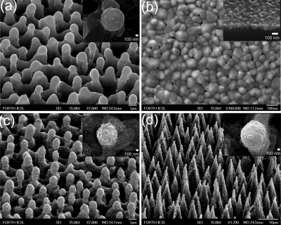
Figure 7 shows the SEM pictures of the initial microstructured silicon surfaces as well as those acquired after the deposition of the nanograined ZnO film. We have prepared three types of surfaces, namely, sample A (the Si microstructure prepared at 0.21 J∕cm2), sample B (the Si microstructure prepared at 1.1 J∕cm2), and a ZnO nanostructured thin film. As clearly seen, a significant enhancement of the nanoscale roughness is attained. The micrometer-scale spikes have been decorated by nanosized ZnO protrusions, resulting in a hierarchically rough surface. The nanoscale features are more pronounced in sample A than in sample B. The corresponding contact angles were measured to be ∼120° for sample A and ∼140° for sample B. The stoichiometry of the ZnO protrusions was confirmed by energy dispersive x-ray spectroscopy (EDX) measurements performed on different positions on the structured surfaces. The elemental analysis, performed by EDX, of the spectrum was found to be similar to that obtained in the flat part of the sample outside the spikes area.
Figure 7.
(a) Side SEM view of Si surfaces structured by femtosecond irradiation at laser fluence of 0.17 J∕cm2. The inset shows a higher magnification of the top of a single microcone. (b) Top SEM view of a nanograined ZnO film prepared by PLD on a flat Si substrate. A cross-sectional image of the film is shown in the inset. (c) Side SEM view of a ZnO coated Si surface structured by femtosecond irradiation at laser fluence of 0.17 J∕cm2. Higher magnification of the top of a single microcone (the scale bar is 100 nm), shown in the inset, reveals the double scale roughness of the structures. (d) The same as in (a) but at laser fluence of 2.1 J∕cm2. Reproduced with permission from E. L. Papadopoulou et al., J. Phys. Chem. C 113, 2891 (2009). Copyright 2009. American Chemical Society.
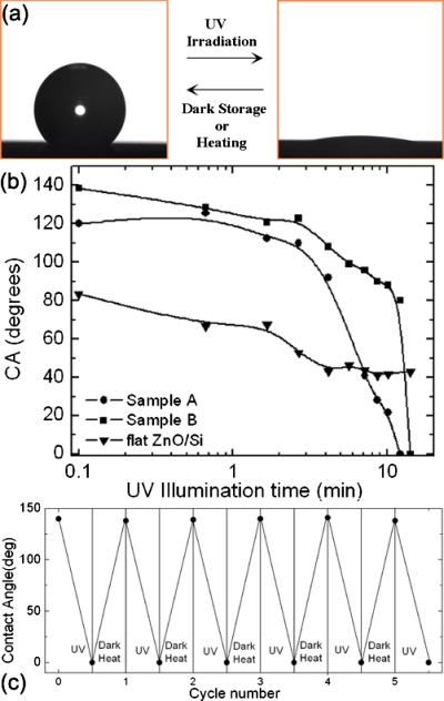
Figure 8a depicts the contact angle evolution with UV illumination time for the different ZnO structures employed. The UV source used was a KrF excimer laser (248 nm) with an intensity of 14 mW cm−2 at the position of the samples. Both structured samples exhibit a significant photoinduced transition to superhydrophilicity, reaching a nearly zero contact angle in a short time. More importantly, the contact angle reduction rate, being a measure of the efficiency of the light induced process, is higher than that observed in other ZnO structures.73, 77 On the contrary, the nanostructured ZnO thin film shows a weak response to UV irradiation, as the wetting angle change in this case is much smaller for the same irradiation time. It should be emphasized that the aforementioned wettability changes are reversible, since both dark storage and thermal heating reconvert the superhydrophilic surfaces to their original states. After the UV irradiation, the samples were placed in the dark. The hydrophobicity for samples A and B was restored within 24 h, whereas the flat sample requires 7 day storage in order to return to its initial wetting state. Alternatively, thermal heating at 200 °C for 1 h can return all surfaces to their original hydrophobic state, speeding up the reversibility process. All samples were subjected to numerous switching cycles [Fig. 8b], without observing any deterioration of either the irradiation efficiency or the reversibility behavior.
Figure 8.
(a) Photographs of the shape of a water droplet on sample B before (left) and after (right) UV illumination. The transition from hydrophobicity to superhydrophilicity is reversible upon dark storage or thermal heating. (b) Dependence of the water contact angle on the UV illumination for sample A (ZnO nanostructured thin film on the Si microstructure prepared at 0.21 J∕cm2), sample B (ZnO nanostructured thin film on the Si microstructure prepared at 1.1 J∕cm2), and a ZnO nanostructured thin film. (c) Reversible switch from hydrophobicity to superhydrophilicity for sample B under the alternation of UV irradiation and thermal heating at 200 °C for 1 h. Sample A exhibits a similar response.
In conclusion, the above methodology can be employed to control the structural and morphological properties of ZnO structures, resulting in reversible efficient wettability changes. Such capability may be useful for self-cleaning coatings and microfluidic applications, as well as for studying the photoswitchable wettability of surfaces and its relation to micro- and nanostructures.
Electroswitchable surfaces
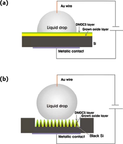
Liquid actuation and manipulation using electrowetting-on-dielectric (EWOD) is becoming a promising tool toward the realization of modern microfluidic devices.78, 79 Indeed, EWOD has been used to demonstrate a variety of microfluidic operations such as droplet actuation,80, 81 dispensing,82 mixing,83 and splitting.84 Apart from lab-on-chip devices,85, 86 applications related to adjustable lenses,87 display technology,88 fiber optics,89 and microelectromechanical systems90 have been demonstrated. Typically, an electrowettable surface consists of a conductive lower layer with a dielectric layer sandwiched between the lower electrode and an upper hydrophobic material, which lowers the surface energy and confers a larger initial hydrophobicity [Fig. 9a]. A slightly conductive droplet creates a capacitance defined by the contact area of the droplet and the substrate. When a voltage, V, is applied between the conductor and the insulator, an electric charge is created and this alters the surface free energy balance. The additional energy per unit area due to the capacitance is given by (1∕2)⋅C⋅V2, where for a simple planar surface the capacitance per unit area is C=εr⋅εo∕d, where εr is the dielectric constant of the layer, d is its thickness, and εo is the dielectric constant of air. It is found that on a flat surface the equilibrium CA for a given voltage, θe(V), is given by the expression
| (1) |
otherwise known as the Lippmann–Young equation. Here, γlv is the liquid-air interfacial tension, γesl is the electric-field induced surface tension, and θo is the CA prior to application of the electric field. The prediction of this equation is that a voltage will cause the CA of a droplet to decrease so that a reduction in hydrophobicity occurs. Although this effect is seen in practice, there is a problem of CA saturation after a threshold voltage. The phenomenon is also reversible, although partial reversibility is often observed.
Figure 9.
The electrowetting-on-dielectric system for (a) flat and (b) structured Si substrates.
There are many factors which affect the performance of an electrowettable surface, such as the surface tension of the materials. In order to reduce voltage requirements, which is desirable for microfluidic chip technology, the basic strategy is to use a thinner dielectric film with higher dielectric constant and dielectric strength. However, it is understood that a more important limiting factor is the small range of the actuated CAs before the electric charge saturation in the dielectric occurs. This range depends on the surface wetting angle at zero voltage, and the higher this value the greater the attainable CA variation. Therefore, it would be highly advantageous to fabricate electrowettable superhydrophobic surfaces. Up to now, there are few reports in the literature demonstrating EWOD on superhydrophobic nanostructured surfaces. The main difficulty is caused by the high degree of roughness exhibited by superhydrophobic surfaces, which leads to substantial spatial separation between the liquid and the underlying electrode, strongly impeding the electrowetting effect.91 Among them, only one has demonstrated reversibility;92 this is attributed to the fact that when the drop wedged in the structures it does not go up, leading to an irreversible EWOD effect. It is thus evident that achieving reversible electrowetting on superhydrophobic surfaces is not only a technical challenge, but a real asset for potential applications.
In the following, we will present reversible EWOD of liquid droplets on dual-rough superhydrophobic black silicon (Si) surfaces, produced by ultrafast pulsed laser micro∕nanostructuring.70 Following irradiations, the laser patterned surfaces were covered with a thin layer of thermally grown (1000 °C in ambient conditions) silicon oxide; this would serve as the dielectric layer for the EWOD experiments. The thickness of this layer was determined by means of spectroscopic ellipsometry performed on the flat part of the oxidized Si wafer, outside the irradiated area. For the planar device it was measured to be (210±5) nm, whereas for the black Si device it was (190±5) nm. However, the oxidized surface became superhydrophilic and as a result a water droplet wets completely the patterned area. To perform EWOD experiments and achieve superhydrophobicity, the oxidized surfaces were coated with DMDCS silane monolayers. Figure 9b shows the final EWOD device. The same surface treatment was used for flat Si samples that were not microstructured.
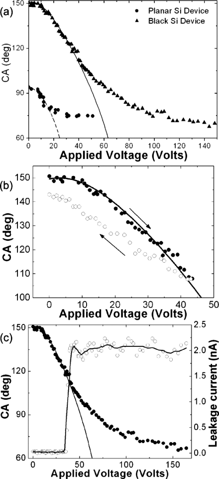
During the EWOD experiments, the apparent CA of a glycerol droplet on modified flat and structured Si surfaces was measured as a function of the applied voltage. Details of the experimental process can be found elsewhere.94 The detailed evolution of the CAs for flat Si and a superhydrophobic black Si sample, prepared at a high fluence of 1.69 J∕cm2, as a function of the bias voltage is plotted in Fig. 10a. For the flat surface, the CA decreases as the bias voltage increases until it saturates when the CA change becomes ∼20°. The change before saturation is reversible and the CA returns back to its initial value after reducing the applied bias. On the contrary, partial reversibility was recorded in the case of the black Si sample. This is presented in Fig. 10b showing that the behavior is partly reversible as the CA returns close but not exactly at the initial value after lowering the applied bias to 0 V. Reversibility is preserved upon several repetition cycles provided that the applied voltage falls within 0 and 44 V.
Figure 10.
(a) Contact angle of an 85% glycerol drop as a function of applied voltage for (a) a flat (solid circles) and a black Si surface (solid triangles) of a laser fluence of 1.69 J∕cm2. The lines represent the fits to Eqs. 1, 3 with parameters shown in the text. (b) Reversibility of the EWOD effect; the arrows indicate the decrease∕increase of the applied bias, respectively. (c) CA (on the left y-axis) and leakage current (on the right y-axis) dependence on the applied voltage. The solid line is a fit to Eq. 3 with parameters shown in the text; the dashed line is a guide to the eye.
The dashed line in Fig. 10a represents fits to the data according to the behavior predicted by the Lippmann–Young equation [Eq. 1]. For the fit, we have used in Eq. 1 the measured oxide thickness, the silicon oxide dielectric constant εr=3.9 (Ref. 93) and γlv=65.7 mN∕m, and the Young’s CA θo=94°. The fit indicates that the experimentally observed behavior is in good agreement with the one predicted by Eq. 1 until CA saturation occurs. On the contrary, this is not true for the corresponding CA(V) dependencies measured on the structured sample, suggesting that a proper modification of Eq. 1 is required in order to account for the effect of superhydrophobicity on the EWOD behavior. In a superhydrophobic surface, the liquid does not completely impale the roughened solid. As a result, air pockets are trapped inside the features underneath the liquid, which sits above a composite surface made of solid and air. This is the so-called Cassie–Baxter state94 where the apparent contact angle θCB is an average between the value on air (that is 180°) and on the flat solid (that is θo) and is given by
| (2) |
where f defines the fraction of the projected solid surface that is wet by the liquid. In this case, Eq. 1 is modified to be95
| (3) |
It is important to note that Eq. 3 is otherwise identical to Eq. 1, but the Young angle has been replaced by the initial CA of the hydrophobic surface, and there is the fractional area f in the voltage term. Since f<1, the EWOD effect is much weaker on highly hydrophobic surfaces than on normal ones. The solid line in Fig. 10a is a fit to the experimental data according to the behavior predicted by the modified Lippmann–Young equation 3 with θCB=151° and f=0.21.
When the applied field exceeds a critical value, the apparent contact angle tends to saturate. CA saturation is not uncommon in EWOD systems; however, its origin is still undetermined. Figure 10c shows the recorded leakage current through the superhydrophobic EWOD device as a function of the applied voltage. A large jump in the leakage current was observed at about the same voltage where the onset of saturation takes place. Much higher applied voltage causes dramatic increase of the current, which is also indirectly detected by the bubbles rising inside the liquid drop, indicating hydrolysis. Our results are consistent with dielectric breakdown behavior regarding reversibility.96 Silicon oxide breakdown is a local effect, appearing as small spots of the order of 10 nm on the dielectric surface,97 and it is found to be reversible as long as the leakage current is kept low.98 When excessive current is passed, e.g., due to high applied voltage, breakdown propagates and thermal damage is caused.97, 98
In summary, the EWOD properties of dual-rough Si surfaces with different micro- and nanomorphological characteristics were investigated and compared to planar Si ones. The results reveal two potential advantages of using dual-rough black Si instead of planar Si in EWOD applications. On one hand, the roughened surface provides extension of the available EWOD voltages that can be applied before breakdown occurs. On the other hand, the changes in the CA, before the systems reach saturation, are higher. In conclusion, our EWOD system exhibits remarkable CA reversibility in air environment and may constitute dual-rough black Si, an important material in integrated microfluidic systems.99
pH responsive surfaces
A great number of responsive materials and material surfaces are based on macromolecules often coined with names such as “stimuli-responsive,” “smart,” “intelligent,” or “environment-sensitive” polymers.100 This is due to the fact that synthetic polymers offer a wealth of opportunities to design sophisticated materials by variation of the length, chemical composition, architecture, and topology of the chains. Smart polymers can reversibly alter their physicochemical properties even upon slight changes in the conditions of the surrounding environment; they respond by modifying the conformation and∕or location of backbone, side chains, segments, pendant, as well as end-groups, which gives rise to cooperative phase transitions occurring at the micro- and macroscale. A prominent example of smart macromolecules involves the so-called pH responsive polymers, in which protonation∕deprotonation events occurring due to pH variations around their effective pKα values alter the degree of ionization of the monomer repeat units (weak acid or weak base behavior), thus modifying the polymer-solvent interactions leading to changes of the polymer chain conformations and to the formation of smart polymer nanostructures.101, 102
Controlled reorganization of interfacial layers based on environment-sensitive polymers has been widely utilized for the design and fabrication of smart∕responsive material surfaces. Polymer brushes created by end-grafting stimuli-sensitive polymers103, 104 onto surfaces with hierarchical micro∕nanoroughness have been frequently utilized for the development of such smart surfaces that can respond to changes in pH temperature and solvent quality.
We have developed polymer functionalized pH-responsive surfaces that exhibit hierarchical micro- and nanostructured roughness, which can reversibly switch between superhydrophilicity at low pH and superhydrophobicity and water repellency at high pH.71 To the best of our knowledge, this is the first time that such a surface is realized. To date, polymers that become superhydrophobic at low pH and anionic and superhydrophilic at high pH have been reported;105 however, that imposes certain limitations for many applications, e.g., the anionic polymer surfaces cannot interact with DNA, enzymes, and polyanionic drugs by attractive electrostatic interactions. In this respect, surfaces functionalized with pH-responsive polymers, which become cationic and superhydrophilic, are especially desirable.
The responsive surfaces were prepared by “grafting from” poly(2-(diisopropylamino)ethyl methacrylate), PDPAEMA, brushes onto dual-length-scale roughened silicon substrates using surface-initiated atom transfer radical polymerization. PDPAEMA homopolymer is a pH-responsive weak polybase, which undergoes a reversible protonation∕deprotonation process upon changing the solution pH and, thus, can interact with anionic substances at low pH when it becomes cationic. The switching behavior of the surface is driven by the combined effects of the polymer chemical response and the dual-scale roughness of the surface, which remains unaffected by the polymerization process.
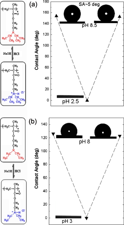
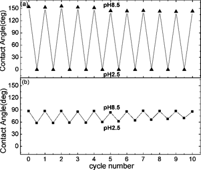
Images of a water droplet lying on the PDPAEMA functionalized artificial surface are shown in Fig. 11a following successive immersions in solutions at pH 8.5 and pH 2.5. The complete wetting (superhydrophilicity) following the immersion at pH 2.5 and the superhydrophobic behavior (CA 154±1°) following the immersion at pH 8.5 are due to the reversible protonation∕deprotonation of DPAEMA (the pKα of PDPAEMA is 6.3). Figure 11b also shows the respective behavior for a dual-scale roughened surface, functionalized with a poly(2-(diethylamino)ethyl methacrylate), PDEAEMA, brush (the pKα of PDEAEMA is 7.3). The responsive behavior is evident in this case as well; however, the behavior after immersion at pH 10 is far from superhydrophobic with the CA reaching only ∼126±1°. It is noted that the water CA on a PDPAEMA brush on a flat Si surface is ∼88±1°, whereas that on a PDEAEMA brush on a flat Si surface is ∼83±1° (both in the deprotonated state). Therefore, it is the combined effect of the dual-scale roughness and the sufficient hydrophobicity of the material that is necessary in order for a surface to become superhydrophobic; the incorporation of only two extra methyl groups per monomer unit (Fig. 1) can lead to a “hydrophobic enough” material. The average CAs of water drops residing on the PDPAEMA functionalized artificially structured surface are shown in Fig. 12a following successive immersions at pH 8.5 and pH 2.5. It is evident that the responsiveness of the functionalized hierarchically structured surface holds for at least ten cycles, with very stable values of the CAs of both the superhydrophobic and the superhydrophilic states. Thus, it is proven that the polymer brush synthesized onto the dually roughened surface is resilient to pH variations, which is especially important since the brush is immersed in basic and strongly acidic solutions. The PDPAEMA brush synthesized onto a flat Si surface is responsive as well [Fig. 12b] with CA value variations; however, that is only within ∼30°.
Figure 11.
(a) Characteristic images of water droplets residing on the PDPAEMA functionalized hierarchically structured surface following immersion at pH 8.5, pH 2.5 (complete wetting), and again at pH 8.5. The scheme shows the protonation/deprotonation process of PDPAEMA. (b) Characteristic images of water droplets residing on the PDEAEMA functionalized artificially structured surface following immersion at pH 8, pH 3 (complete wetting), and again at pH 8. The scheme shows the protonation/deprotonation process of PDEAEMA. Reproduced with permission from E. Stratakis et al., Chem. Commun. (Cambridge) 46, 4136 (2010). Copyright 2010. The Royal Society of Chemistry.
Figure 12.
(a) Average contact angle values of water drops residing on the PDPAEMA functionalized hierarchically structured surface following successive immersions at pH 8.5 and pH 2.5. Reproduced with permission from E. Stratakis et al., Chem. Commun. (Cambridge) 46, 4136 (2010). Copyright 2010. The Royal Society of Chemistry.
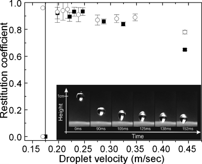
The inset of Fig. 13 presents the selected snapshots of a free-falling water droplet (radius of 1.35 mm) impinging on the PDPAEMA functionalized artificial surface following its immersion to a pH 8.5 solution. The drop impacts the surface with a velocity that corresponds to a dimensionless Weber number of We=3.5. The surface is so water-repellent that the drop bounces back numerous times and selected maxima of its trajectory are shown as a function of time. The drop finally comes to rest on the surface after ∼250 ms. The restitution coefficient, ε=υ′∕υ coefficient, is deduced from the recorded video images and is shown in Fig. 13 as a function of the impact velocity υ in comparison with that of the natural lotus leaf. The similarity of the restitution coefficient as well as the threshold velocity value (necessary to avoid sticking of the drops) between the functionalized artificial and the lotus leaf surface is evident.
Figure 13.
Restitution coefficient as a function of the impact velocity for the PDPAEMA functionalized surface, after immersion at pH 8.5 (filled squares), and a natural lotus leaf surface (open circles). The line signifies the threshold velocity. Inset: selected snapshots of a water drop impinging on the surface. The maxima of the drop trajectory are shown as a function of time.
In summary, pH-responsive surfaces were developed, which can reversibly switch between superhydrophilic at low pH and superhydrophobic and water-repellent at high pH. The surfaces were developed by “grafting from” a pH-sensitive polymer brush onto controlled hierarchically micro- and nanostructured substrates, which mimic the hierarchical morphology of natural water-repellent surfaces. The responsive behavior is due to the combined effect of the hierarchical micro-and nanoroughness and the hydrophobicity of the functionalizing polymer brush. We demonstrate that the water-repellent state of such surfaces requires appropriate hydrophobicity of the functionalizing polymer, whereas for the first time we characterize the contact angle hysteresis along with the static contact angle data for the responsive surfaces in their superhydrophobic state.
BIOLOGICAL CELL ADHESION AND WETTABILITY FOR TISSUE ENGINEERING
The in vitro or in vivo synthesis of a tissue, an organ, or part of them has involved a unique collaboration between biologists, engineer, chemists, and physicists. As a consequence, an expanded database of knowledge has been arisen over the past decade. This literature attempts to apprehend the principles of cell biology, to find the relationships between material properties and bioadhesive outcomes, and finally to apply this growing database in creating biomaterials that mimic the natural extracellular environment.106 It has been established that cell-cell interaction and cell-substratum adhesion play a crucial role not only in physiological biological processes such as differentiation, morphogenesis, tissue regeneration, wound healing, and so forth, but they can be involved in biological problems such as carcinogenesis, thrombogenesis, and abnormal embryogenesis. In this respect, a comprehensive study and understanding of mechanisms involved in cell-material interaction is considerably necessary for the creation of cell-biomaterial unit suitable for tissue engineering application.
A variety of cell adhesion mechanisms is responsible for assembling cells together and, along with their connections to the internal cytoskeleton, determines the overall architecture of the tissue.107 By the other side, material properties such as surface chemistry, energy, and morphology are recognized as key factors in controlling cell assembly into 3D features.106, 108, 109, 110, 111 Consequently, the ability to tailor the surface morphology and chemistry could be beneficial for the use of such structures as model surfaces for the systematic exploration of the role of 3D micro∕nanomorphology and∕or surface energy on cell adhesion and growth. It is also desirable for the scaffold to enable facile methods of modification to incorporate integral sensors for monitoring purposes and bioactive moieties for influencing cell behavior.
In this respect, the implementation of laser engineered hierarchically structured Si surfaces for the development of tissue scaffolds is investigated. It is demonstrated that it is possible to preferentially tune cell adhesion and growth by choosing the proper combinations of topography and chemistry of 3D biomimetic micro∕nanostructures. In Sec. 2A it is presented that our direct-writing laser technique enables simultaneous structuring at both the micro- and the nanolength scales. Variation of laser fluence caused remarkable changes in the morphological features of the spikes such as height (microscale roughness), sharpness, porosity, and nanoscale roughness (Fig. 1). Consequently, the etched substrates produced should allow more 3D free spaces perpendicular to the culture plane and should also provide physical cues to facilitate cell adhesion and spreading. It has also been shown that the laser texturing of Si allows the controlled modification of the wetting properties of the surface through a systematic and reproducible variation of the surface roughness (Fig. 4). Therefore, ultrafast laser etched surfaces, with the capacity to exquisitely control the size of pores, the micro∕nanotopography, and the surface wettability, represent a promising culture scaffold that might enable a multiparametric assessment of the various factors that affect cell behavior with far-reaching implications for tissue engineering.
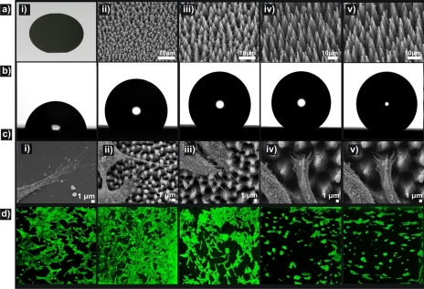
Three series of Si substrates were examined.112 Type A corresponds to the, as-prepared, patterned Si surfaces comprising four samples with gradient roughness ratios, denoted as A1–A4. Type B corresponds to the same substrates coated with a hydrophilic thermally grown oxide layer (B1–B4). (c) Type C corresponds to the same substrates coated by a hydrophobic silane layer. Types A and C samples had shown the same qualitative results and will be considered as equivalent cases thereafter. In all series, the corresponding flat surfaces were tested as control samples. The principal properties of the above substrate types are summarized in Table 1. Cell adhesion experiments were performed using the fibroblast NIH∕3T3 cell line in order to investigate whether these surfaces were able to modulate cellular responses. SEM and fluorescence microscopy images (Fig. 14) show that the number of attached cells per unit area decreased as the roughness ratio and CA increased, denoting that cell attachment was favored on more hydrophilic surfaces.
Table 1.
General properties of the different samples used for this study. Series A denotes as-prepared patterned Si surfaces and series B denotes the patterned surfaces after thermal oxidation treatment.
| Sample | Flat Si | Oxidized flat Si | A1 | B1 | A2 | B2 | A3 | B3 | A4 | B4 |
|---|---|---|---|---|---|---|---|---|---|---|
| Laser fluence (J∕cm2) | ⋯ | 0.34 | 0.56 | 0.90 | 1.69 | |||||
| Roughness ratio | ⋯ | 2.6 | 3.3 | 6.0 | 6.9 | |||||
| Contact angle (deg) | 67 | 25 | 105 | 20 | 121 | 20 | 152 | 0 | 154 | 0 |
Figure 14.
(a) Picture of a polished Si wafer (i) and side SEM views of the as-prepared Si spikes surfaces structured at four different laser fluencies: (ii) 0.34 J∕cm2 (A1), (iii) 0.56 J∕cm2 (A2), (iv) 0.90 J∕cm2 (A3), (v) 1.69 J∕cm2 (A4). (b) Photographs of water droplets on the patterned Si surfaces. (c) SEM micrographs of fibroblast cells adhering to the surfaces. (d) Confocal laser microscopy pictures of fibroblast cells cultured for 3 days on the respective surfaces. Reproduced with permission from A. Ranella et al., Acta Biomater. 6, 2711 (2010). Copyright 2010. Elsevier.
Besides fibroblasts, Si microstructured substrates have been utilized to enable primary neurons to grow in 3D, without using synthetic extracellular matrix (ECM) coatings, or chemotropic factors.113 Neurons depend on surface support more than other cells, but readily adhere to surfaces coated with ECM proteins. Moreover, brain development and neuronal network formation depend on an intricate blueprint of axon guidance, dendritic arborisation, and synapse formation cues. The challenge to comprehend the multitude of cues neurons receive, process, and direct, in vivo, and to simulate 3D cultures in vitro, has been addressed; however, the results are limited.114, 115 The importance of three-dimensional neuronal cultures can be realized if one thinks that the dimensionality of the network has a strong impact on its connectivity, and therefore plays an important role for its possible behavior.116
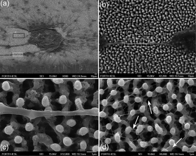
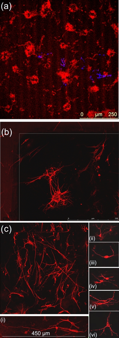
In our studies, primary neuronal cells were cultured on laser patterned Si substrates in the absence of chemotropic factors or synthetic ECM. Details of the substrate preparation and culture process can be found elsewhere.12, 112 Similar to fibroblasts, neuron cell attachment was favored on more hydrophilic surfaces. Microstructured roughness in the form of spikes promoted the adhesion of single or clusters of neurons to the substrate [Fig. 15a]. In contrast, only few cells survived on a flat Si substrate used as a control that verified the role of roughness in the absence of synthetic ECM. The cells developed into a dynamic cellular aggregate, with long neurites sprouting over the spikes surface [Fig. 15b]. The integrity and uniform sprouting observed suggest the biocompatibility of the neuronal population with the surface. The protrusions of the neurolemma grew over the spikes, engulfed their top, and incorporated them to form a web [Fig. 15c]. Moreover, a network of nanoscale thin neuritic extensions was formed along the third dimension (−z axis) utilizing the space toward the base of the spikes [Fig. 15d].
Figure 15.
(a) Neuronal cluster on the Si spikes area. (b) Detail corresponding to white lined inset of (a), showing a long neurite that has attached and grown over the spikes. (c) Detail corresponding to white lined inset of (b), showing protrusions of neurolemma growing over and engulfing the top of the spikes. (d) Detail corresponding to black lined inset of (a), showing the 3D web of cytoplasmic processes growing along the direction vertical to the culture plane. The arrows indicate how multiple processes may initiate from one neurite. Reproduced with permission from E. L. Papadopoulou et al., Tissue Eng Part C Methods 16, 497 (2010). Copyright 2010. Mary Ann Liebert.
As it has been already mentioned, the correlation between the substrate characteristics and cell adhesion highly depends on the level of surface free energy.117 Originally, Baier suggested that the amount of bioadhesion does not correlate well with the surface energy of the substrate.118 He reported the existence of a surface energy window with minimal adhesion, while substrates exhibiting surface energies outside the defined range could absorb considerable amounts of biomass. In contrast, Schakenraad et al.119 found a sigmoidal dependence of cell spreading on surface energy, indicating a sharp transition at low surface energies between poor and good adherence. However, for the measurement of adhesion in the mentioned reports, it was not used one particular type of substratum modified to display different CAs, but a large number of different polymers and glasses. Thus, the effects of surface chemistry and wettability on cell adhesion cannot be separated.
The physical behavior of hydrolyzed living cells may be regarded as a drop of liquid. The adhesion of this cell liquid can be affected by the surface wettability due to the increased or decreased contact area, which is proportional to the solid-liquid interfacial adhesive force. Alternatively, a living cell can be described by tensegrity models,120 which consider that cellular shape and adhesion are largely influenced by the cytoskeleton; the cell tends to form focal adhesions in locations that balance cytoskeletal forces. In this respect, surface wettability is crucial as it describes to what extent the surface is exposed to culture medium and subsequent protein adsorption. A reduction in adhesive protein adsorption due to a decreased liquid-surface interfacial area may detrimentally affect the ability of cells to form adhesions. In any case, the surface energy influences the contact area of the cell membrane with the substrate, while the profile of the membrane could change depending on the wettability of the adjacent solid.
In order to understand the cell response on substrates with different roughness, one has to consider the effect of the macroscopic roughness on wettability, which has been theoretically approached by two different models. In the Wenzel model,121 the liquid is assumed to wet the entire rough surface, without leaving any air pockets underneath it. The apparent CA, θw, is given by the following equation:
| (4) |
where rw is the ratio of the unfolded surface to the apparent area of contact under the droplet, and θo is the contact angle on a flat surface of the same nature as the rough. Since rw is always greater than unity, this model predicts that the contact angle will decrease∕increase with surface roughness for an initially hydrophilic (θo<90°)∕hydrophobic (θo>90°) surface.
In contrast, Cassie and Baxter (CB) assumed94 that the liquid does not completely permeate the rough surface because air pockets get trapped underneath it. The liquid is thus said to be in a “fakir” or the Cassie–Baxter state and the apparent CA, θCB, is an average of the flat surface, θo, and the value for full hover over the flat surface (that is 180°) and is given by Eq. 2. As f is always lower than unity, this model always predicts enhancement of hydrophobicity, independent of the value of the initial contact angle θo. The lower the value of f, the smaller the solid-liquid contact area and the higher the increase in the measured contact angle.
Following the results presented in Fig. 14, it is obvious that the CA values measured for the structured substrates are consistent with the CB model, because in contrast to the Wenzel model, it predicts a rise in the CA upon enhancement of the roughness of an initially hydrophilic (θ<90°) surface. Hence, for the superhydrophobic substrates, where the solid-liquid contact area is minimal, water cannot penetrate the roughness elements and therefore an intervening air layer persists. This resembles the case of many aquatic and semiaquatic arthropods (insects and spiders), which are rendered water-repellent due to a rough, waxy exterior festooned with hairs.122 Owing this superhydrophobic integument, the respiratory demands of these species are facilitated by a thin intervening layer of trapped air, which is called “plastron,” and maintained along their body surface. This air layer is visible at nonzero reflection angles and is responsible for the silvery underwater reflections from aquatic species.
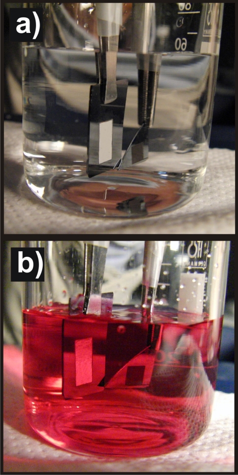
Indeed, as shown in Fig. 16, when a water-repellent spike-substrate is immersed in water or cell culture liquid, it glistens with a silvery sheen, indicating that a sheathing film of air remains on the submerged surface. Conversely, for more hydrophilic substrates, the fraction of the wetted area increases and the surface glistening disappears as a result of increasing liquid penetration. Finally, for superhydrophilic substrates, the contact area is maximized and water completely penetrates the roughness elements. Therefore, taking into account that cell culture medium is aqueous, the interaction of cell membrane with the underlying substrate may be governed by the degree of surface wettability and thus surface energy.
Figure 16.
Pictures of the as-prepared superhydrophobic (sample A1, on the left) and oxidized superhydrophilic (sample B4, on the right) patterned regions immersed in water (a) and cell culture medium (b), respectively. The silvery shine is visible only on the superhydrophobic patterned region of the A1 sample while it is absent on flat regions and the less hydrophobic patterned area of the B4 sample. Reproduced with permission from A. Ranella et al., Acta Biomater. 6, 2711 (2010). Copyright 2010. Elsevier.
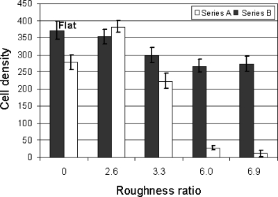
Fibroblast and neuron spreading is promoted on hydrophilic or high surface energy rough substrates due to the permeation of the culture liquid in the structures, allowing cells to take advantage of the high surface-area-to-volume ratio offered by the structured substrates. On the contrary, adhesion is almost impossible on ultrahydrophobic or low surface energy rough substrates, as the penetration of the culture liquid on the structures is inhibited. The results presented in Fig. 17 for fibroblasts suggest the existence of a switching function for the structured Si surface characteristics, from fibroblast adhesive to fibroblast repulsive, when a critical combination of roughness and wettability, and thus surface energy, is attained. This switching effect agrees with the sigmoidal dependence suggested by Baier and may be attributed to the critical transition from the Wenzel to Cassie–Baxter states.123
Figure 17.
Cell density of fibroblasts on flat and oxidized Si, the as-prepared (series A) and oxidized (series B) patterned Si surfaces after 72 h incubation. All experiments were done on triplicates and the cell density values shown are the calculated mean values. Reproduced with permission from A. Ranella et al., Acta Biomater. 6, 2711 (2010). Copyright 2010. Elsevier.
Further support to this statement is coming form the results obtained after substrate oxidation, where the highly rough substrate is converted from ultrahydrophobic to ultrahydrophilic, and accordingly the wettability switches from Cassie–Baxter to Wenzel states. As shown in Fig. 17, in this case, a remarkable change in cell behavior was observed, since fibroblasts spreading and viability seems to be comparable between highly rough oxidized surfaces (B3, B4) and small rough oxidized or nonoxidized surfaces (B1 or A1, respectively). The importance of surface chemistry was tested also on neuronal survival with the same manner, utilizing a geometrically identical Si substrate, following thermal oxidation. Neurons sensed the vertical microstructured roughness and adhered. However, a prominent feature on oxidized hydrophilic area was the extended cellular death. Although the oxidized Si spikes (B2) maintained the same geometrical microenvironment as the bare Si spikes, they did not allow long-term neuronal survival, indicating that neuron cells, unlike fibroblasts, preferentially adhered and have grown on more hydrophobic, although not superhydrophobic as well, surfaces. Consequently, biomaterial roughness is not a stand-alone prerequisite for cell survival and growth, but it rather requires the synergistic effect of surface chemistry.
It should be noted that the primary neuronal culture conditions used favored the sole growth of primary neurons, and confocal microscopy was employed to confirm the immunofluorescence of tubulin beta III, which is specific for mature neurons, that there was no glial feeder layer on the substrates under study [Fig. 18a]. Hence, the immunostaining enabled us to confirm the neuronal specificity of our cultures, to verify the shape of adhesion on the substrates, and to measure a significant increase in length for some of the neurons [Fig. 18b]. It is worth emphasizing that neuronal adhesion was not superficial. This was established by the attachment, growth, and elongation of neurites on the substrates in all three dimensions. The undeniable proof of outstanding adhesion properties was derived from the electron micrographs, demonstrating how the neuronal membranes incorporated the tips of the spikes as their own. Besides promoting neuronal adhesion, the microscale roughness in synergy with the surface chemistry allowed the formation of an exquisitely organized 3D neuritic network. The use of hydrophobic, Si microstructures enabled the “autografting” of these structures by the neurons. The ability of the neurons to liquefy and adjust their cytoskeletal dynamics is intrinsic. Nevertheless, these intracellular processes that drive membrane extensions, as migration or filopodial lengthening, still work against the membrane’s mechanical properties. In this study, we demonstrated that inherent neuronal guidance cues were sufficient to win over steady-state membrane mechanics. The outcome was to allow the filopodia of growth cones to explore this permissive 3D microenvironment, and in the absence of multidirectional cues, to “decide” depending on the shortest distance.
Figure 18.
(a) Primary neuronal culture immunostained both for beta III tubulin (red) and GFAP (blue) at 5 days in vitro. The micrograph demonstrates the low numbers of GFAP immunopositive cells and staining colocalization. (b) Neuron-specific immunohistochemistry and confocal microscopy using antibeta III tubulin primary antibody. Corner of spike area showing some cells in a cluster (scale bar of 250 mm). (c) Illustration of the phenomenal neuritic sprouting and extension on the substrate surface. (i) Some of the neurons showed extraordinary extension. Examples of different neuronal types and the formation of varicosities [(ii)–(v)] were placed on the right. Reproduced with permission from E. L. Papadopoulou et al., Tissue Eng Part C Methods 16, 497 (2010). Copyright 2010. Mary Ann Liebert.
Thus, we can conclude that the sharp transition from superhydrophobicity to superhydrophilicity is accompanied by a transition in cell adherence depending on cell type. This sharp transition between the two extreme wetting states may be potentially a useful tool toward controlling cell behavior on culture substrates. Furthermore, a nonmonotonic dependence of fibroblast adhesion on wettability could be detected (Fig. 5), which is qualitatively in accordance with the Baier model. Optimum cell adhesion was obtained for small roughness ratios, independent of the CA values and surface chemistry (Fig. 15). This observation was also supported by the SEM images of Fig. 14, where the total number of filopodial processes was much higher in surfaces with low roughness. The proliferation and immigration of adhesion depended cells was realized though exertion of contact strain.124 The filopodia of growth cones play an important role in feeling the environment. On a surface exhibiting a suitable roughness, the cell soma and the processes would adopt a shape complementary to the surface profile, achieving maximum contact area, and therefore, interfacial force. This force will benefit cell adhesion and spreading on the substrate surface, so that cells recognize and migrate to areas of optimum roughness.
There have been a lot of reports on studying the effect of roughness and surface energy on cellular responses. Both discrete specimens and surface energy gradients were used in these studies and many different outcomes have been observed. In some studies, cell functions are enhanced on hydrophilic surfaces,119, 125, 126, 127 whereas in others, cell functions are enhanced on hydrophobic surfaces.128, 129, 130, 131 While in other cases, surface energy has no effect on cell functions131, 132 or cell functions have a maximum at an intermediate surface energy.127, 133, 134 This broad range of outcomes is possibly a result of the wide variability in experimental conditions such as cell types, incubation times, culture conditions, surface chemistries, and topographies. Most studies investigate the separate effect of nano- or microroughness, respectively.133, 134 On the contrary, due to demanding design requirements, the synergistic effect of roughness at micro- and nanoscales on cell response has been limitlessly studied.135 The present study focuses on cell response on surfaces possessing micro∕nanotopography (i.e., microstructures decorated by secondary nanofeatures), thus investigating the synergistic effect of micro- and nanoscale roughness on cell adhesion and viability.
It was also shown that a dual-rough surface amplifies hydrophilicity toward superhydrophilicity or hydrophobicity toward water repellency and accordingly enhances cell-phobicity or cell-philicity for the culture substrate. The cell spreading dependence on surface energy has an important heuristic impact in the area of biomaterials research and it is crucial to understand this dependence on a molecular basis. Mechanistically, one has to go back to the first reaction between a biomaterial and the organism, which is protein adsorption. At high CAs, i.e., in the hydrophobic range, different proteins are adsorbed compared to the hydrophilic range. The adsorbed protein layers comprising different proteins on the surface could therefore result in differential tissue reactions, which would lead to specific bioadhesion. The investigation of protein adsorption to these artificial surfaces needs further exploration.
In summary, it is shown that laser-structured Si micro- and nanorough spike scaffolds with controllability of roughness ratio and surface chemistry can serve as a novel means to elucidate the 3D cell-biomaterial interactions in vivo. The dependency of cell response of different cell types on the artificial structures was investigated and clarified that a fundamental parameter that determines cell adhesion on 3D substrates is not solely the degree of roughness or surface chemistry, but the synergy of both, which determines the wettability or surface energy of the culture substrate. Indeed, a proper change in the surface energy for the same degree of roughness can switch the behavior from cell-phobic to cell-philic and vice versa, and this transition is always accompanied by a similar sharp transition in surface wettability. However, and in accordance with previous theoretical models describing cell response, a nonmonotonic dependence of fibroblast adhesion on wettability is found. Although it appears to be a general tendency that adhesion is favored on hydrophilic substrates, it is observed that cells’ spreading becomes optimum on low-rough substrates, independent of their wettability. This indicates that cell attachment is further enhanced and facilitated by a proper form and size of surface topography.
As pointed out in Sec. 2A, the different structures obtained via our laser structuring technique can be transferred to various types of soft materials, including biopolymers, through replication molding techniques. The simplicity of the structuring process and the flexibility of fast patterning by laser beam scanning, together with its potential to tailor the surface energy of different classes of materials, are certainly useful for creating patterned interfaces on biomaterials devices and tissue engineering.
SUMMARY AND FUTURE PERSPECTIVES
The present article is focused on surface micro-∕nanostructuring of materials using femtosecond duration laser pulses as well as the functionalization methodologies used for controlling materials properties. Direct irradiation of materials by ultrafast laser pulses often induces modifications leading to complex micro- and nanoscale surface structures, which mimic the morphology of surfaces found in nature. We demonstrate that ultrafast laser micro∕nanostructured materials can be exploited for diverse emerging applications including biomimetic and responsive alteration of static and dynamic wetting response in microfluidics and applications related to scaffold biocompatibility and tissue engineering. However, the wealth of arising possibilities in laser-based micro- and nanofabrication and the number of new approaches to nanoscale fabrication prescribe a future where control of artificial biomaterial structure and subsequent functionality can be accomplished with a level of sophistication that we cannot presently envisage.
References
- Stratakis E. and Zorba V., in Biomimetic and Bioinspired Nanomaterials, Nanomaterials for the Life Sciences Vol. 7, edited by Kumar C. S. S. R. (Wiley, Weinheim, 2010), Chap. 11. [Google Scholar]
- Xia F. and Jiang L., Adv. Mater. (Weinheim, Ger.) 20, 2842 (2008). 10.1002/adma.200800836 [DOI] [Google Scholar]
- Shiu J. -Y., Kuo C. -W., Chen P., and Mou C. -Y., Chem. Mater. 16, 561 (2004). 10.1021/cm034696h [DOI] [Google Scholar]
- Bartlett P. N., Baumberg J. J., Birkin P. R., Ghanem M. A., and Netti M. C., Chem. Mater. 14, 2199 (2002). 10.1021/cm011272j [DOI] [Google Scholar]
- Woodward I., Schofield W. C. E., Roucoules V., and Badyal J. P. S., Langmuir 19, 3432 (2003). 10.1021/la020427e [DOI] [Google Scholar]
- Martines E., Seunarine K., Morgan H., Gadegaard N., Wilkinson C. D. W., and Riehle M. O., Nano Lett. 5, 2097 (2005). 10.1021/nl051435t [DOI] [PubMed] [Google Scholar]
- Lau K. K. S., Bico J., Teo K. B. K., Chhowalla M., Amaratunga G. A. J., Milne W. I., McKinley G. H., and Gleason K. K., Nano Lett. 3, 1701 (2003). 10.1021/nl034704t [DOI] [Google Scholar]
- Stratakis E., Ranella A., Farsari M., and Fotakis C., Prog. Quantum Electron. 33, 127 (2009). 10.1016/j.pquantelec.2009.06.001 [DOI] [Google Scholar]
- Zorba V., Tzanetakis P., Fotakis C., Spanakis E., Stratakis E., Papazoglou D. G., and Zergioti I., Appl. Phys. Lett. 88, 081103 (2006). 10.1063/1.2177653 [DOI] [Google Scholar]
- Zorba V., Ph.D. thesis, University of Crete, 2007. [Google Scholar]
- Her T. -H., Finlay R. J., Wu C., Deliwala S., and Mazur E., Appl. Phys. Lett. 73, 1673 (1998). 10.1063/1.122241 [DOI] [Google Scholar]
- Zorba V., Persano L., Pisignano D., Athanassiou A., Stratakis E., Cingolani R., Tzanetakis P., and Fotakis C., Nanotechnology 17, 3234 (2006). 10.1088/0957-4484/17/13/026 [DOI] [PubMed] [Google Scholar]
- Barberoglou M., Zorba V., Stratakis E., Spanakis E., Tzanetakis P., Anastasiadis S. H., and Fotakis C., Appl. Surf. Sci. 255, 5425 (2009). 10.1016/j.apsusc.2008.07.130 [DOI] [Google Scholar]
- Zorba V., Boukos N., Zergioti I., and Fotakis C., Appl. Opt. 47, 1846 (2008). 10.1364/AO.47.001846 [DOI] [PubMed] [Google Scholar]
- Karabutov A. V., Frolov V. D., Loubnin E. N., Simakin A. V., and Shafeev G. A., Appl. Phys. A: Mater. Sci. Process. 76, 413 (2003). 10.1007/s00339-002-1715-y [DOI] [Google Scholar]
- Wu C., Crouch C. H., Zhao L., Carey J. E., Younkin R., Levinson J. A., Mazur E., Farreli R. M., Gothoskar P., and Karger A., Appl. Phys. Lett. 78, 1850 (2001). 10.1063/1.1358846 [DOI] [Google Scholar]
- Sheehy M. A., Winston L., Carey J. E., Friend C. M., and Mazur E., Chem. Mater. 17, 3582 (2005). 10.1021/cm049029i [DOI] [Google Scholar]
- Chen Y. and Vertes A., Anal. Chem. 78, 5835 (2006). 10.1021/ac060405n [DOI] [PubMed] [Google Scholar]
- Runyon M., Johnson-Kerner B., and Ismagilov R., Angew. Chem., Int. Ed. 43, 1531 (2004). 10.1002/anie.200353428 [DOI] [PubMed] [Google Scholar]
- Domachuk P., Tsioris K., Omenetto F. G., and Kaplan D. L., Adv. Mater. (Weinheim, Ger.) 22, 249 (2010). 10.1002/adma.200900821 [DOI] [PubMed] [Google Scholar]
- Oliveira N. M., Neto A. I., Song W., and Mano J. F., Appl. Phys. Express 3, 085205 (2010). 10.1143/APEX.3.085205 [DOI] [Google Scholar]
- Choi C. -H. and Kim C. -J., Phys. Rev. Lett. 96, 066001 (2006). 10.1103/PhysRevLett.96.066001 [DOI] [PubMed] [Google Scholar]
- Lu C., Xie Y., Yang Y., Cheng M. M.-C., Koh C. -G., Bai Y., Lee L. J., and Juang Y. -J., Anal. Chem. 79, 994 (2007). 10.1021/ac0615798 [DOI] [PubMed] [Google Scholar]
- Khan Malek C. G., Anal. Bioanal. Chem. 385, 1351 (2006). 10.1007/s00216-006-0514-2 [DOI] [PubMed] [Google Scholar]
- Vorobyev A. Y. and Guo C., Opt. Express 18, 6455 (2010). 10.1364/OE.18.006455 [DOI] [PubMed] [Google Scholar]
- Vorobyev A. Y. and Guo C., Appl. Phys. Lett. 94, 224102 (2009). 10.1063/1.3117237 [DOI] [Google Scholar]
- Wang Z. K., Zheng H. Y., and Xia H. M., Microfluid. Nanofluid. 10, 225 (2011). 10.1007/s10404-010-0662-8 [DOI] [Google Scholar]
- Zhang D., Chen F., Fang G., Yang Q., Xie D., Qiao G., Li W., Si J., and Hou X., J. Micromech. Microeng. 20, 075029 (2010). 10.1088/0960-1317/20/7/075029 [DOI] [Google Scholar]
- Sugioka K., Hanada Y., and Midorikawa K., Laser Photonics Rev. 4, 384 (2009). [Google Scholar]
- Gattass R. R. and Mazur E., Nat. Photonics 2, 219 (2008). 10.1038/nphoton.2008.47 [DOI] [Google Scholar]
- Blossey R., Nature Mater. 2, 301 (2003). 10.1038/nmat856 [DOI] [PubMed] [Google Scholar]
- Callies M. and Quere D., Soft Matter 1, 55 (2005). 10.1039/b501657f [DOI] [Google Scholar]
- Nakajima A., Fujishima A., Hashimoto K., and Watanabe T., Adv. Mater. (Weinheim, Ger.) 11, 1365 (1999). [DOI] [Google Scholar]
- Barthlott W. and Neinhuis C., Planta 202, 1 (1997). 10.1007/s004250050096 [DOI] [PubMed] [Google Scholar]
- Contact angle hysteresis is defined as the difference between the advancing and receding contact angles.
- Richard D. and Quéré D., Europhys. Lett. 48, 286 (1999). 10.1209/epl/i1999-00479-1 [DOI] [Google Scholar]
- Richard D. and Quéré D., Europhys. Lett. 50, 769 (2000). 10.1209/epl/i2000-00547-6 [DOI] [Google Scholar]
- Richard D., Clanet C., and Quéré D., Nature (London) 417, 811 (2002). 10.1038/417811a [DOI] [PubMed] [Google Scholar]
- Sun T. L., Feng L., Gao C. F., and Jiang L., Acc. Chem. Res. 38, 644 (2005). 10.1021/ar040224c [DOI] [PubMed] [Google Scholar]
- Feng L., Li S., Li Y., Zhang L., Zhai J., Song Y., Liu B., Zhiang L., and Zhu D., Adv. Mater. (Weinheim, Ger.) 14, 1857 (2002). 10.1002/adma.200290020 [DOI] [Google Scholar]
- Zorba V., Stratakis E., Barberoglou M., Spanakis E., Tzanetakis P., Anastasiadis S. H., and Fotakis C., Adv. Mater. (Weinheim, Ger.) 20, 4049 (2008). 10.1002/adma.200800651 [DOI] [Google Scholar]
- Ashurst W. R., Carraro C., and Maboudian R., IEEE Trans. Device Mater. Reliab. 3, 173 (2003). 10.1109/TDMR.2003.821540 [DOI] [Google Scholar]
- Öner D. and McCarthy T. J., Langmuir 16, 7777 (2000). 10.1021/la000598o [DOI] [Google Scholar]
- Wasserman S. R., Tao Y. -T., and Whitesides G. M., Langmuir 5, 1074 (1989). 10.1021/la00088a035 [DOI] [Google Scholar]
- Zorba V., Stratakis E., Barberoglou M., Spanakis E., Tzanetakis P., and Fotakis C., Appl. Phys. A: Mater. Sci. Process. 93, 819 (2008). 10.1007/s00339-008-4757-y [DOI] [Google Scholar]
- Zhao B., Moore J. S., and Beebe D. J., Science 291, 1023 (2001). 10.1126/science.291.5506.1023 [DOI] [PubMed] [Google Scholar]
- Beebe D. J., Moore J. S., Yu Q., Liu R. H., Kraft M. L., Jo B. -H., and Devadoss C., Proc. Natl. Acad. Sci. U.S.A. 97, 13488 (2000). 10.1073/pnas.250273097 [DOI] [PMC free article] [PubMed] [Google Scholar]
- LaVan D. A., McGuire T., and Langer R., Nat. Biotechnol. 21, 1184 (2003). 10.1038/nbt876 [DOI] [PubMed] [Google Scholar]
- Christian K., Andreas H., and Wolfgang S., Anal. Chem. 74, 219A (2002). 10.1021/ac0219849 [DOI] [PubMed] [Google Scholar]
- Roy I., Rao M. V. S., and Gupta M. N., Biotechnol. Appl. Biochem. 37, 9 (2003). 10.1042/BA20020043 [DOI] [PubMed] [Google Scholar]
- Jeong B. and Gutowska A., Trends Biotechnol. 20, 305 (2002). 10.1016/S0167-7799(02)01962-5 [DOI] [PubMed] [Google Scholar]
- Ruan C. M., Ong K. G., Mungle C., Paulose M., Nickl N. J., and Grimes C. A., Sens. Actuators B 96, 61 (2003) 10.1016/S0925-4005(03)00486-6 [DOI] [Google Scholar]; Samuel J. D. J. S., Ruther P., Frerichs H. - P., Lehmannc M., Paulb O., and Ruhe J., Sens. Actuators B 110, 218 (2005). 10.1016/j.snb.2005.01.032 [DOI] [Google Scholar]
- Nosonovsky M. and Bhushan M., Philos. Trans. R. Soc. London, Ser. A 367, 1511 (2009) 10.1098/rsta.2009.0008 [DOI] [PubMed] [Google Scholar]; Nosonovsky M. and Bhushan M.,Curr. Opin. Colloid Interface Sci. 14, 270 (2009). 10.1016/j.cocis.2009.05.004 [DOI] [Google Scholar]
- Genzer J. and Efimenko K., Biofouling 22, 339 (2006). 10.1080/08927010600980223 [DOI] [PubMed] [Google Scholar]
- Xia F., Zhu Y., Feng L., and Jiang L., Soft Matter 5, 275 (2009). 10.1039/b803951h [DOI] [Google Scholar]
- de Crevoisier G., Fabre P., Corpart J. -M., and Leibler L., Science 285, 1246 (1999). 10.1126/science.285.5431.1246 [DOI] [PubMed] [Google Scholar]
- Dupont-Gillain Ch. C., Adriaensen Y., Derclaye S., and Rouxhet P. G., Langmuir 16, 8194 (2000). 10.1021/la000326l [DOI] [Google Scholar]
- Rosario R., Gust D., Hayes M., Jahnke F., Springer J., and Garcia A., Langmuir 18, 8062 (2002). 10.1021/la025963l [DOI] [Google Scholar]
- Athanassiou A., Lygeraki M. I., Pisignano D., Lakiotaki K., Varda M., Fotakis C., Cingolani R., and Anastasiadis S. H., Langmuir 22, 2329 (2006). 10.1021/la052122g [DOI] [PubMed] [Google Scholar]
- Lahann J., Mitragotri S., Tran T. -N., Kaido H., Sundaram J., Choi I. S., Hoffer S., Somorjai G. A., and Langer R., Science 299, 371 (2003). 10.1126/science.1078933 [DOI] [PubMed] [Google Scholar]
- Xulu P. M., Filipcsei G., and Zrínyi M., Macromolecules 33, 1716 (2000) 10.1021/ma990967r [DOI] [Google Scholar]; Guo H. -X., Zhao X. -P., Guo H. -L., and Zhao Q., Langmuir 19, 9799 (2003). 10.1021/la034948t [DOI] [Google Scholar]
- Anastasiadis S. H., Retsos H., Pispas S., Hadjichristidis N., and Neophytides S., Macromolecules 36, 1994 (2003). 10.1021/ma0211129 [DOI] [Google Scholar]
- Isaksson J., Tengstedt C., Fahlman M., Robinson N., and Berggren M., Adv. Mater. (Weinheim, Ger.) 16, 316 (2004). 10.1002/adma.200306131 [DOI] [Google Scholar]
- Minko S., Patil S., Datsyuk V., Simon F., Eichhorn K. -J., Motornov M., Usov D., Tokarev I., and Stamm M., Langmuir 18, 289 (2002). 10.1021/la015637q [DOI] [Google Scholar]
- Retsos H., Gorodyska G., Kiriy A., Stamm M., and Creton C., Langmuir 21, 7722 (2005). 10.1021/la050054s [DOI] [PubMed] [Google Scholar]
- Koberstein J. T., Duch D. E., Hu W., Lenk T. J., Bhatia R., Brown H. R., Lingelser J. -P., and Gallot Y., J. Adhes. 66, 229 (1998). 10.1080/00218469808009967 [DOI] [Google Scholar]
- Retsos H., Kiriy A., Senkovskyy V., Stamm M., Feldstein M. M., and Creton C., Adv. Mater. (Weinheim, Ger.) 18, 2624 (2006). 10.1002/adma.200600315 [DOI] [Google Scholar]
- Xia F., Ge H., Hou Y., Sun T., Chen L., Zhang G. Z., and Jiang L., Adv. Mater. (Weinheim, Ger.) 19, 2520 (2007). 10.1002/adma.200602334 [DOI] [Google Scholar]
- Papadopoulou E. L., Barberoglou M., Zorba V., Manousaki A., Pagkozidis A., Stratakis E., and Fotakis C., J. Phys. Chem. C 113, 2891 (2009). 10.1021/jp8085057 [DOI] [Google Scholar]
- Barberoglou M., Zorba V., Pagozidis A., Fotakis C., and Stratakis E., Langmuir 26, 13007 (2010). 10.1021/la101138u [DOI] [PubMed] [Google Scholar]
- Stratakis E., Mateescu A., Barberoglou M., Vamvakaki M., Fotakis C., and Anastasiadis S. H., Chem. Commun. (Cambridge) 2010, 4136. 10.1039/c003294h [DOI] [PubMed] [Google Scholar]
- Feng X., Feng L., Jin M., Zhai J., Jiang L., and Zhu D., J. Am. Chem. Soc. 126, 62 (2004). 10.1021/ja038636o [DOI] [PubMed] [Google Scholar]
- Kenanakis G., Stratakis E., Vlachou K., Vernardou D., Koudoumas E., and Katsarakis N., Appl. Surf. Sci. 254, 5695 (2008). 10.1016/j.apsusc.2008.03.055 [DOI] [Google Scholar]
- Badre C., Pauporte T., Turmine M., and Lincot D., Nanotechnology 18, 365705 (2007). 10.1088/0957-4484/18/36/365705 [DOI] [Google Scholar]
- Lao C. S., Li Y., Wong C. P., and Wang Z. L., Nano Lett. 7, 1323 (2007). 10.1021/nl070359m [DOI] [PubMed] [Google Scholar]
- Papadopoulou E. L., Varda M., Kouroupis-Agalou K., Androulidaki M., Chikoidze E., Galtier P., Huyberechts G., and Aperathitis E., Thin Solid Films 516, 8141 (2008). 10.1016/j.tsf.2008.04.022 [DOI] [Google Scholar]
- Sun R., Nakajima A., Fujishima A., Wanatabe T., and Hashimoto K., J. Phys. Chem. B 105, 1984 (2001). 10.1021/jp002525j [DOI] [Google Scholar]
- Mugele F. and Baret J. -C., J. Phys.: Condens. Matter 17, R705 (2005). 10.1088/0953-8984/17/28/R01 [DOI] [Google Scholar]
- Girault H. H., Nature Mater. 5, 851 (2006). 10.1038/nmat1772 [DOI] [PubMed] [Google Scholar]
- Pollack M. G., Shenderov A. D., and Fair R. B., Lab Chip 2, 96 (2002). 10.1039/b110474h [DOI] [PubMed] [Google Scholar]
- Kuo J. S., Spicar-Mihalic P., Rodriguez I., and Chiu D. T., Langmuir 19, 250 (2003). 10.1021/la020698p [DOI] [Google Scholar]
- Ren H., Fair R. B., and Pollak M. G., Sens. Actuators B 98, 319 (2004). 10.1016/j.snb.2003.09.030 [DOI] [Google Scholar]
- Fowler J., Moon H., and Kim C. -J., IEEE 15th International Conference on MEMS, Las Vegas, NV, 2002, pp. 97–100.
- Fair R. B., Srinivasan V., Ren H., Paik P., Pamula V. K., and Pollack M. G., Tech. Dig. - Int. Electron Devices Meet. 2003, 779. [Google Scholar]
- Srinivasan V., Pamula V. K., and Fair R. B., Lab Chip 4, 310 (2004). 10.1039/b403341h [DOI] [PubMed] [Google Scholar]
- Cho S. K., Moon H. J., and Kim C. J., J. Microelectromech. Syst. 12, 70 (2003). 10.1109/JMEMS.2002.807467 [DOI] [Google Scholar]
- Berge B. and Peseux J., Eur. Phys. J. E 3, 159 (2000). 10.1007/s101890070029 [DOI] [Google Scholar]
- Hayes R. A. and Feenstra B. J., Nature (London) 425, 383 (2003). 10.1038/nature01988 [DOI] [PubMed] [Google Scholar]
- Acharya B. R., Krupenkin T., Ramachandran S., Wang Z., Huang C. C., and Rogers J. A., Appl. Phys. Lett. 83, 4912 (2003). 10.1063/1.1633331 [DOI] [Google Scholar]
- Lee J. and Kim C. J., J. Microelectromech. Syst. 9, 469 (2000). 10.1109/84.896767 [DOI] [Google Scholar]
- Krupenkin T. N., Taylor J. A., Schneider T. M., and Yang S., Langmuir 20, 3824 (2004). 10.1021/la036093q [DOI] [PubMed] [Google Scholar]
- Verplanck N., Galopin E., Camart J. C., Thomy V., Coffinier Y., and Boukherroub R., Nano Lett. 7, 813 (2007). 10.1021/nl062606c [DOI] [PubMed] [Google Scholar]
- Gray P. R., Hurst P. J., Lewis S. H., and Meyer R. G., Analysis and Design of Analog Integrated Circuits, 5th ed. (Wiley, New York, 2009), p. 40. [Google Scholar]
- Cassie A. B. D. and Baxter S., Trans. Faraday Soc. 40, 546 (1944). 10.1039/tf9444000546 [DOI] [Google Scholar]
- Torkelli A., Ph.D. thesis, Helsinki University of Technology, 2004. [Google Scholar]
- Papathanasiou A. G. and Boudouvis A. G., Appl. Phys. Lett. 86, 164102 (2005). 10.1063/1.1905809 [DOI] [Google Scholar]
- Stratakis E., Misra N., Spanakis E., Hwang D. J., Grigoropoulos C. P., Fotakis C., and Tzanetakis P., Nano Lett. 8, 1949 (2008). 10.1021/nl0807171 [DOI] [PubMed] [Google Scholar]
- Nafría M., Sune J., and Aymerich X., J. Appl. Phys. 73, 205 (1993). 10.1063/1.353884 [DOI] [Google Scholar]
- Whitesides G. M., Nature (London) 442, 368 (2006). 10.1038/nature05058 [DOI] [PubMed] [Google Scholar]
- Kumar A., Srivastavaa A., Yu Galaev I., and Mattiasson B., Prog. Polym. Sci. 32, 1205 (2007). 10.1016/j.progpolymsci.2007.05.003 [DOI] [Google Scholar]
- Rodríguez-Hernández J., Chécot F., Gnanou Y., and Lecommandoux S., Prog. Polym. Sci. 30, 691 (2005). 10.1016/j.progpolymsci.2005.04.002 [DOI] [Google Scholar]
- Vamvakaki M., Papoutsakis L., Katsamanis V., Afchoudia T., Fragouli P., Iatrou H., Hadjichristidis N., Armes S. P., Sidorov S., Zhirov D., Zhirov V., Kostylev M., Bronstein L. M., and Anastasiadis S. H., Faraday Discuss. 128, 129 (2005). 10.1039/b403414g [DOI] [PubMed] [Google Scholar]
- Minko S., J. Macromol. Sci., Part C: Polym. Rev. 46, 397 (2006). [Google Scholar]
- Uhlmann P., Ionov L., Houbenov N., Nitschke M., Grundke K., Motornov M., Minko S., and Stamm M., Prog. Org. Coat. 55, 168 (2006). 10.1016/j.porgcoat.2005.09.014 [DOI] [Google Scholar]
- Xia F., Feng L., Wang S., Sun T., Song W., Jiang W., and Jiang L., Adv. Mater. (Weinheim, Ger.) 18, 432 (2006). 10.1002/adma.200501772 [DOI] [Google Scholar]
- Liu X. M., Lim J. Y., Donahue H. J., Dhurjati R., Mastro A. M., and Vogler E. A., Biomaterials 28, 4535 (2007). 10.1016/j.biomaterials.2007.06.016 [DOI] [PMC free article] [PubMed] [Google Scholar]
- Gumbiner B. M., Cell 84, 345 (1996). 10.1016/S0092-8674(00)81279-9 [DOI] [PubMed] [Google Scholar]
- Cretel E., Pierres A., Benoliel A. M., and Bongrand P., Cellular and Molecular Bioengineering 1, 5 (2008). 10.1007/s12195-008-0009-7 [DOI] [PMC free article] [PubMed] [Google Scholar]
- Khang D., Lu J., Yao C., Haberstroh K. M., and Webster T. J., Biomaterials 29, 970 (2008). 10.1016/j.biomaterials.2007.11.009 [DOI] [PubMed] [Google Scholar]
- Lim J. Y. and Donahue H. J., Tissue Eng. 13, 1879 (2007). 10.1089/ten.2006.0154 [DOI] [PubMed] [Google Scholar]
- Lim J. Y., Shaughnessy M. C., Zhou Z. Y., Noh H., Vogler E. A., and Donahue H. J., Biomaterials 29, 1776 (2008). 10.1016/j.biomaterials.2007.12.026 [DOI] [PubMed] [Google Scholar]
- Ranella A., Barberoglou M., Bakogianni S., Fotakis C., and Stratakis E., Acta Biomater. 6, 2711 (2010). 10.1016/j.actbio.2010.01.016 [DOI] [PubMed] [Google Scholar]
- Papadopoulou E. L., Samara A., Barberoglou M., Manousaki A., Pagakis S. N., Anastasiadou E., Fotakis C., and Stratakis E., Tissue Eng Part C Methods 16, 497 (2010). 10.1089/ten.tec.2009.0216 [DOI] [PubMed] [Google Scholar]
- Lee J., Cuddihy M. J., and Kotov N. A., Tissue Eng Part B Rev 14, 61 (2008). 10.1089/teb.2007.0150 [DOI] [PubMed] [Google Scholar]
- Pautot S., Wyart C., and Isacoff E. Y., Nat. Methods 5, 735 (2008). 10.1038/nmeth.1236 [DOI] [PMC free article] [PubMed] [Google Scholar]
- Eckmann J. P., Feinerman O., Gruendlinger L., Moses E., Soriano J., and Tlusty T., Phys. Rep. 449, 54 (2007). 10.1016/j.physrep.2007.02.014 [DOI] [Google Scholar]
- Schakenraad J. M., in Biomaterials Science: An Introduction to Materials in Medicine, edited by Ratner B. D., Hoffman A. S., Schoen F. J., and Lemons J. E. (Elsevier Science, USA, 1996). [Google Scholar]
- Adhesion in Biological Systems, edited by Manly R. S. (Academic, New York, 1970). [Google Scholar]
- Schakenraad J. M., Busscher H. J., Wildevuur C. R. H., and Arends J., J. Biomed. Mater. Res. 20, 773 (1986). 10.1002/jbm.820200609 [DOI] [PubMed] [Google Scholar]
- Ingber D. E., J. Cell. Sci. 104, 613 (1993). [DOI] [PubMed] [Google Scholar]
- Wenzel R. N., Ind. Eng. Chem. 28, 988 (1936). 10.1021/ie50320a024 [DOI] [Google Scholar]
- Flynn M. R. and Bush J. W. M., J. Fluid Mech. 608, 275 (2008). 10.1017/S0022112008002048 [DOI] [Google Scholar]
- Lafuma A. and Quere D., Nature Mater. 2, 457 (2003). 10.1038/nmat924 [DOI] [PubMed] [Google Scholar]
- Dembo M. and Wang Y. L., Biophys. J. 76, 2307 (1999). 10.1016/S0006-3495(99)77386-8 [DOI] [PMC free article] [PubMed] [Google Scholar]
- Lee S. J., Khang G., Lee Y. M., and Lee H. B., J. Colloid Interface Sci. 259, 228 (2003). 10.1016/S0021-9797(02)00163-7 [DOI] [PubMed] [Google Scholar]
- van der Valk P., Vanpelt A. W. J., Busscher H. J., Dejong H. P., Wildevuur C. R. H., and Arends J., J. Biomed. Mater. Res. 17, 807 (1983). 10.1002/jbm.820170508 [DOI] [PubMed] [Google Scholar]
- Vanwachem P. B., Beugeling T., Feijen J., Bantjes A., Detmers J. P., and Vanaken W. G., Biomaterials 6, 403 (1985). 10.1016/0142-9612(85)90101-2 [DOI] [PubMed] [Google Scholar]
- Lee J. H., Jeong B. J., and Lee H. B., J. Biomed. Mater. Res. 34, 105 (1997). [DOI] [PubMed] [Google Scholar]
- Lee J. H., Lee S. K., Khang G., and Lee H. B., J. Colloid Interface Sci. 230, 84 (2000). 10.1006/jcis.2000.7080 [DOI] [PubMed] [Google Scholar]
- Redey S. A., Razzouk S., Rey C., Bernache-Assollant D., Leroy G., Nardin M. et al. , J. Biomed. Mater. Res. 45, 140 (1999). [DOI] [PubMed] [Google Scholar]
- Ruardy T. G., Moorlag H. E., Schakenraad J. M., VanderMei H. C., and Busscher H. J., J. Colloid Interface Sci. 188, 209 (1997). 10.1006/jcis.1997.4769 [DOI] [Google Scholar]
- Ruardy T. G., Schakenraad J. M., Vandermei H. C., and Busscher H. J., J. Biomed. Mater. Res. 29, 1415 (1995). 10.1002/jbm.820291113 [DOI] [PubMed] [Google Scholar]
- Jager M., Zilkens C., Zanger K., and Krauspe R., J. Biomed. Biotechnol. 2007, 69036. [DOI] [PMC free article] [PubMed] [Google Scholar]
- Kennedy S. B., Washburn N. R., Simon C. G., and Amis E. J., Biomaterials 27, 3817 (2006). 10.1016/j.biomaterials.2006.02.044 [DOI] [PubMed] [Google Scholar]
- Zhao G., Raines A. L., Wieland M., Schwartz Z., and Boyan B. D., Biomaterials 28, 2821 (2007). 10.1016/j.biomaterials.2007.02.024 [DOI] [PMC free article] [PubMed] [Google Scholar]


