Abstract
This study presents a novel approach to decant supernatant on a centrifugal platform. By manipulating the centrifugally induced pressure and the elastic deformation of the plastic lids in the decanting chamber, fixed amounts of the supernatant can be decanted into the detection chamber at lower rotational speeds. The experimental results showed that decanted volume is affected by the volume of deformation and the operating parameters. Factors that influence the decanting ratio are also discussed. This approach has the advantages of simple design and low manufacturing cost; further, it has no need of surface modification. It has been applied to on-disk separation of plasma from whole blood, and the results showed good stability and repeatability.
INTRODUCTION
“Micrototal analysis systems” or “lab-on-a-chip” systems have been intensely studied in recent years. Many applications have been developed in the field of biology, chemistry, and medicine. Advantages of lab-on-a-chip devices include the reduction in reagent∕sample consumption, parallel processing, and short turnaround time. One of the most important aspects of lab-on-a-chip technologies is the ability to integrate various sample preparation steps (such as separation, metering, and mixing) in one single device. It is especially important for point-of-care devices, in which the complete assay protocol needs to be carried out from whole blood to analytical results. It is also desirable that the devices can be operated automatically to eliminate the need for skilled technicians and to reduce the number of human operating errors.
In clinical tests, the first sample preparation procedure is usually plasma extraction from whole blood. By removing the red blood cells from the whole blood, the signal noise can be greatly reduced during analysis.1 In the past, partial separation of the cells from the whole blood has been reported by researchers using magnetic susceptibility,2, 3 acoustic force,4 filtration,5, 6 bifurcation law, or plasma skimming techniques.7, 8, 9 Most of these methods were designed for continuous plasma separation.
This study focuses on “batch type” plasma separation, especially on centrifugal microfluidic devices such as “lab-on-a-disk”10, 11 applications. The major advantage of this technology is that it is capable of actuating liquid with low volume by centrifugation. Therefore, it is an ideal platform for point-of-care diagnostics. Quite a few applications have been developed on this platform, such as enzyme linked immunosorbent assays,12, 13, 14, 15 small molecule assays,16, 17 nucleic acid analysis,18, 19, 20, 21 and liquid component analysis.22 For the whole blood assays on this platform, plasma extraction mainly relies on separation of cells from whole blood by centrifugation and supernatant decanting techniques. The major difficulty for the decanting process is that the high rotational speed (usually 3000 rpm) required for blood separation may cause most of the burst valves to fail. It has been reported that the separated plasma can be released through a wax valve,23, 24, 25 which can be melted upon application of thermal energy. Other approaches utilize capillary action and siphoning effects17, 26 to deliver the plasma into reaction chamber. These studies have successfully demonstrated on-chip plasma extraction from whole blood. However, installation of wax valves or hydrophilic surface modification might increase both the cost and the manufacturing difficulties. Therefore, a simple, robust, and affordably manufacturable decanting method is desired. In this study, we present a novel approach to decant supernatant by manipulating the centrifugally induced pressure and the elastic behavior of the plastic lids of the chamber.
EXPERIMENTAL
The centrifugal platform used in this study is a sandwich-like structure with two polycarbonate disks on both sides and a double-sided pressure-sensitive adhesive layer in the middle. The size of the polycarbonate disk is similar to that of a commercial digital video disk with a diameter of 120 mm. Disks with two different thicknesses, 0.56 and 0.52 mm, respectively, were used in this study in order to observe the effect of disk thickness on the deformation of plastic lids while maintaining the rigidity of the platform. The thickness of the pressure-sensitive adhesive is 0.1 mm. The fluidic structures were made by patterning the pressure-sensitive adhesive layer with a cutting plotter (CAMM-1 CX24, Roland). The entry and venting holes were drilled on the disks with a CNC plotter (3D MDX-20, MODELA).
To observe the flow characteristics under high rotational speeds, a flow visualization system similar to one mentioned in a previous study27 was built. The spinning control system consisted of a motor (HC-KFS053, Mitsubishi) and a motor controller (PCI-7332, National Instruments). A computer program (LabVIEW, National Instruments) was used to manage the rotational speed of the motor. The image-capturing system was composed of a complementary metal oxide semiconductor (CMOS) camera (SI-SV642C, EPIX), a stroboscope (DT-311N, SHIMPO), and a triggering sensor (PZ-V11, Keyence). The triggering sensor synchronized the stroboscope with the spin frequency of the disk by detecting the reflected signals from the trigger mark on the disk. Computer software (Vision, National Instruments) was used to analyze the experimental results from the images acquired by the CMOS camera.
DEFORMATION OF PLASTIC LIDS
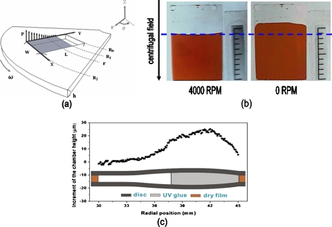
The general principles for the deformation of plastic lids are described below. A rectangular chamber on a centrifugal platform is rotated at a rotational speed ω [Fig. 1a]. The inner and outer sides of the chamber are located at radii R0 and R2, respectively. The chamber is filled with liquid and the air∕liquid interface is located at radius R1. Vents are made at radius R0 and are open to atmosphere. By using a boundary condition P=0 (gauge pressure) at R1, the centrifugally induced pressure at radius r (R2≥r≥R1) is
| (1) |
The centrifugally induced pressure increases as the radius increases.
Figure 1.
(a) Schematic illustration of a rectangular chamber on a centrifugal platform. (b) Photograph of the chamber at a high rotational speed (4000 rpm) and still image of the chamber (0 rpm). (c) The measured height of the deformed chamber along the radial direction, as estimated by curing UV glue at a rotational speed of 4000 rpm.
As shown in the photos of Fig. 1b, at a high rotational speed (4000 rpm), the centrifugally induced pressure acted on both plastic lids of the chamber and deformed them, which resulted in the decrease of the liquid level. After the rotation of the platform was stopped (0 rpm), the deformation of plastic lids recovered and liquid flowed back to its original level. To verify the effect of deformation, ultraviolet-curable glue was injected into the chamber and cured at a rotational speed of 4000 rpm. The chamber was fixed in epoxy resin and cured at room temperature. The cured sample was then cut open with a diamond blade and the cross section of the chamber was polished with diamond paste. The height of the chamber was measured under a microscope by image analysis software. Figure 1c shows the results of measured chamber heights along radial positions. The major deformation occurred closer to the rim rather than to the center due to higher centrifugally induced pressure near the rim.
SUPERNATANT DECANTING SCHEME
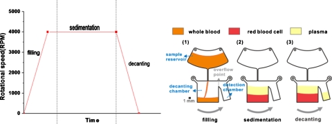
The abovementioned phenomenon of the deformation and recovery of plastic lids is used for supernatant decanting on a centrifugal platform. The separation and decanting of plasma from the whole blood is used as the example. The general protocol for supernatant decanting is shown in Fig. 2. Fixed amount of whole blood is first injected into the sample reservoir. It is delivered into the decanting chamber under centrifugation from 0 to 4000 rpm with acceleration of 100 000 rpm∕s. At this moment, the centrifugally induced pressure deforms the plastic lids of the decanting chamber so that the chamber is accommodating more blood than its original volume. At the same time, the cellular components with higher density start to settle to the outer edge due to the centrifugal force and leave the clear plasma supernatant on the top of the chamber. Finally, the rotation of the centrifugal platform decreases from 4000 to 0 rpm with deceleration of 1000 rpm∕s. Plastic lids resume their original shapes due to the reduction of the centrifugally induced pressure, thus the liquid level rises. The clear supernatant is forced out of the decanting chamber and flows into the detection chamber by centrifugal force.
Figure 2.
Schematic of the supernatant decanting scheme for plasma separation and decanting: (1) filling stage, (2) sedimentation stage, and (3) decanting stage. The platform rotated in counterclockwise direction.
One of the important issues in successful implementation of this scheme is to ensure that the filling time is shorter than the time required for the platform to accelerate to the final rotational speed. If the chamber is filled up before the final rotational speed is reached, the liquid will overflow into the detection chamber due to incomplete deformation. In order to reach the final rotational speed in a short time, the acceleration for the initial filling process is set at 100 000 rpm∕s. In addition, the response time of the deformation, which is defined as the time required for plastic lids to deform to their final shapes, is also important. The response time is measured by the differences between the time required for the liquid to reach its final level and the time required to accelerate to the final rotational speed. As shown in Table 1, since the response time is less than 0.1 s, it can be assumed that the deformation and recovery of the plastic lids occur almost instantaneously.
Table 1.
The response time of the deformation of plastic lids under various accelerations.
| Final rotational speed (rpm) | Acceleration (rpm∕s) | Time required to reach the final rotational speed (s) | Time required to reach the final liquid level (s) | Response time (s) |
|---|---|---|---|---|
| 4000 | 1000 | 4.015 | 4.11 | 0.095 |
| 10 000 | 0.391 | 0.47 | 0.079 | |
| 100 000 | 0.062 | 0.13 | 0.068 |
QUANTIFICATION OF DEFORMED VOLUME
The decanted volume is mainly governed by the deformation of plastic lids, which is similar to the classic problem of the deformation of a flat rectangular plate of uniform thickness with all edges fixed. Solutions are available for a few simple loading conditions such as uniform loading over the entire plate, and uniformly decreasing loading parallel to one side.28 However, since the loading distribution on a centrifugal system is more complicated, it is difficult to achieve an analytical solution.
In order to obtain a basic understanding of the volume of deformation, the problem is simplified by assuming that the chamber is completely filled with liquid (R1=R0). The deformation of the plastic lids is estimated by a beam model with two built-in ends. In this analysis, the change of the liquid level due to the deformation of the lid is also ignored. In addition, because the size of the chamber is usually small in microfluidic applications, curvature is ignored and Cartesian coordinate system is used in this analysis.
The deformation of plastic lids along the X direction is approximated by the deflection of a beam model along the X direction, as shown in Fig. 1. Since the centrifugally induced pressure is approximately equal along the X direction, it can be treated as a beam with a uniformly distributed line load q. Although q is uniform in the X direction, it varies in the Y direction due to centrifugal force,
| (2) |
where b is the width of the beam.
The deflection of the beam can be calculated by the differential equation of the elastic curve,
| (3) |
with boundary conditions
| (4) |
| (5) |
at both sides (X=0 and X=W). The symbol ν is the deflection of the beam in z direction; E is Young’s modulus; I is the moment of inertia of the cross-sectional area of the beam,
| (6) |
where b and h are the width and the height of the cross-sectional area of the beam, respectively.
By integrating the differential equation of the elastic curve with the boundary conditions at both ends, the equation for the deflection curve can be calculated as
| (7) |
By ignoring the constrains near the inner (Y=0) and outer (Y=L) sides of the chamber, the total deformed volume can be calculated by integrating the deflection in both X and Y directions,
| (8) |
Another approach to estimate the chamber deformation is to use a beam model along the Y direction with a distributed load q, as shown in Fig. 1. After a lengthy derivation, the total volume of deformation can be integrated as
| (9) |
Although the deformed volumes derived from both beam models are not exactly the same, their forms are similar. If the geometric factors (width, length, and radial positions) are not considered, the volume of deformation is proportional to the density of the liquid and the square of the rotational speed, and inversely proportional to Young’s modulus and to the cube of the lid thickness,
| (10) |
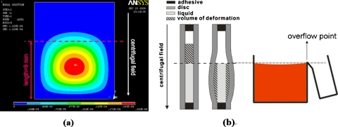
In order to better quantify the deformed volume, numeric simulation on the deformation of the plastic lids was carried out by means of a commercial code package, ANSYS. The mesh was created by defining its geometry and mesh density. After setting the boundary conditions, the loads on each node were specified through the function editor according to the centrifugal field. The deformed volume was calculated by integrating the deflection data from each node [Fig. 3a].
Figure 3.
(a) The schematic of the chamber lid deformation analyzed by ANSYS. (b) Quantification of the volume of deformation by image analysis.
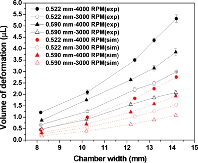
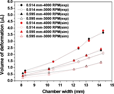
To examine the accuracy of the ANSYS predictions, a series of experiments were conducted by varying the chamber width and rotational speed while keeping the chamber length fixed at 15 mm. The inner and outer sides of the chamber were located at radii of 37 mm (R0) and 52 mm (R2), respectively. The air∕liquid interface was set at radius of 43 mm (R1). As shown in Fig. 3b, the deformed volume of the plastic lids under the air∕liquid interface can be estimated by the differences of the averaged liquid level multiplied by the original thickness of the adhesive. Figure 4 shows the comparison of the volume of deformation between the experimental results measured by image analysis (exp) and the calculation by ANSYS simulation (sim) for a platform made of polycarbonate disks and a pressure-sensitive adhesive. Although the trend of the curve is similar, the volume of deformation measured from experimental results is larger than that from the ANSYS calculation. By examining the cross section of the decanting chamber, delamination between the adhesive and polycarbonate disks was observed near the outer edge of the chamber, which resulted in larger volume of deformation. To minimize the problem of delamination, a platform was made by replacing the pressure-sensitive adhesive with a dry film photoresist (WBR, Dupont), which has a stronger bonding to the disks. As shown in Fig. 5, the volume of deformation from the experiment is similar to that of the ANSYS calculation. Therefore, ANSYS can be used to estimate the volume of deformation for decantation designs as long as the width of the decanting chamber is within the working range.
Figure 4.
Comparison of the volume of deformation between the experimental results measured by image analysis (exp) and calculation by ANSYS simulation (sim) for a platform made of polycarbonate disks and pressure-sensitive adhesive.
Figure 5.
Comparison of the volume of deformation between the experimental results measured by image analysis (exp) and calculation by ANSYS simulation (sim) for a platform made by polycarbonate disks and dry film photoresist.
OTHER FACTORS AFFECTING THE DECANTED VOLUME
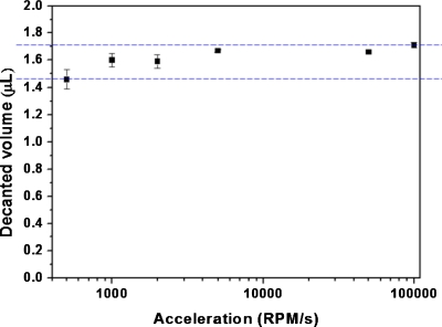
Although the decanted volume is mainly governed by the deformation of the plastic lids, other operating parameters, such as the spinning direction and deceleration in the decanting process, also influence the decanted volume. For the decanting design shown in Fig. 2, spinning in counterclockwise direction, which favors liquid to flow into the detection chamber, results in more stable and generally larger decanted volume than spinning in clockwise direction. In the latter case, liquid tends to move to the opposite direction to the detection chamber and this often results in unstable decanted volume due to flow retardation resulting from the effect of surface tension. In addition, deceleration during the decanting process also affects the decanted volume. For the case shown in Fig. 2 with a counterclockwise spinning direction, the decanted volume slightly increases as the deceleration increases due to inertial effects (Fig. 6).
Figure 6.
The decanted liquid volume under various decelerations.
DECANTING RATIO
The decanting ratio is defined by the percentage of the decanted volume, which is similar to the volume of deformation, to the total liquid volume in the decanting chamber,
| (11) |
in which Vdeformed and Vliquid are defined as the volume of deformation and the liquid volume in the decanting chamber excluding the deformed volume, as shown in Fig. 3b, respectively. From Eq. 11, it is clear that the decanting ratio can be increased by either increasing the volume of deformation or reducing Vliquid, which can be achieved by reducing the thickness of the adhesive. As shown in Table 2, the decanting ratio can be increased from 19% to 29% by reducing the adhesive thickness from 100 to 45 μm. However, as the thickness of the adhesive decreases, flow retardation that resulted from the surface tension becomes more prevalent and often results in lower and unstable decanted volume.
Table 2.
Experimental results of the decanting ratio by varying the adhesive thickness.
| Adhesive thickness (μm) | Total volume (μL) | Decanted volume (μL) | Decanting ratio (%) |
|---|---|---|---|
| 100 | 11.06 | 2.10 | 18.99 |
| 45 | 5.82 | 1.71 | 29.38 |
CONCLUSIONS
A novel approach for supernatant decanting on a centrifugal platform was successfully developed. Supernatant, such as clear plasma, can be gathered by this method. The decanted volume is governed by the deformed volume of plastic lids and operating parameters, such as the rotational direction and deceleration. This fluidic structure is very easy to fabricate and no surface modification is required with this approach. Therefore, the device can easily be mass-produced. Another advantage of this approach is that during the decanting process, a relatively low rotational speed is implemented and the supernatant is decanted into an inner radial region of the disk. Therefore, fluidic functions such as mixing for biochemical reactions can be carried out afterward at a higher rotational speed with the mixing fluidics arranged in the outer radial region. We believe that this approach can be easily integrated with clinical assays for point-of-care applications. In addition, although this approach was originally designed for plasma separation from whole blood, it can also be applied to many fields where supernatant decanting is required, such as soil and water testing.
ACKNOWLEDGMENTS
The authors thank the National Science Council (Grant No. NSC 97-2221-E-035-013) and Feng Chia University (Grant No. TCVGH-FCU97820) for their financial support to this project.
References
- Yager P., Edwards T., Fu E., Helton K., Nelson K., Tam M. R., and Weigl B. H., Nature (London) 442, 412 (2006). 10.1038/nature05064 [DOI] [PubMed] [Google Scholar]
- Inglis D. W., Riehn R., Sturm J. C., and Austin R. H., J. Appl. Phys. 99, 3 (2006). 10.1063/1.2165782 [DOI] [Google Scholar]
- Haik Y., Pai V., and Chen C. J., J. Magn. Magn. Mater. 194, 254 (1999). 10.1016/S0304-8853(98)00559-9 [DOI] [Google Scholar]
- Petersson F., Nilsson A., Jönsson H., and Laurell T., Anal. Chem. 77, 1216 (2005). 10.1021/ac048394q [DOI] [PubMed] [Google Scholar]
- VanDelinder V. and Groisman A., Anal. Chem. 78, 3765 (2006). 10.1021/ac060042r [DOI] [PubMed] [Google Scholar]
- Shim J. S., Browne A. W., and Ahn C. H., Biomed. Microdevices 12, 949 (2010). 10.1007/s10544-010-9449-7 [DOI] [PubMed] [Google Scholar]
- Kersaudy-Kerhoas M., Dhariwal R., Desmulliez M. P. Y., and Jouvet L., Microfluid. Nanofluid. 8, 105 (2010). 10.1007/s10404-009-0450-5 [DOI] [Google Scholar]
- Shevkoplyas S. S., Yoshida T., Munn L. L., and Bitensky M. W., Anal. Chem. 77, 933 (2005). 10.1021/ac049037i [DOI] [PMC free article] [PubMed] [Google Scholar]
- Yang S., Undar A., and Zahn J. D., Lab Chip 6, 871 (2006). 10.1039/b516401j [DOI] [PubMed] [Google Scholar]
- Madou M., Zoval J., Jia G., Kido H., Kim J., and Kim N., Annu. Rev. Biomed. Eng. 8, 601 (2006). 10.1146/annurev.bioeng.8.061505.095758 [DOI] [PubMed] [Google Scholar]
- Ducrée J., Haeberle S., Lutz S., Pausch S., von Stetten F., and Zengerle R., J. Micromech. Microeng. 17, S103 (2007). 10.1088/0960-1317/17/7/S07 [DOI] [Google Scholar]
- He H., Yuan Y., Wang W., Chiou Nan-Rong N. R., Epstein A. J., and Lee L. J., Biomicrofluidics 3, 022401 (2009). 10.1063/1.3116665 [DOI] [PMC free article] [PubMed] [Google Scholar]
- Lai S., Wang S., Luo J., James Lee L., Yang S. -T., and Madou M. J., Anal. Chem. 76, 1832 (2004). 10.1021/ac0348322 [DOI] [PubMed] [Google Scholar]
- Madou M. J., James Lee L., Daunert S., Lai S., and Shih C. -H., Biomed. Microdevices 3, 245 (2001). 10.1023/A:1011419515576 [DOI] [Google Scholar]
- Lee B. S., Lee J. N., Park J. M., Lee J. G., Kim S., Cho Y. K., and Ko C., Lab Chip 9, 1548 (2009). 10.1039/b820321k [DOI] [PubMed] [Google Scholar]
- Steigert J., Grumann M., Dube M., Streule W., Riegger L., Brenner T., Koltay P., Mittmann K., Zengerle R., and Ducrée J., Sens. Actuators, A 130–131, 228 (2006). 10.1016/j.sna.2006.01.031 [DOI] [Google Scholar]
- Steigert J., Brenner T., Grumann M., Riegger L., Lutz S., Zengerle R., and Ducrée J., Biomed. Microdevices 9, 675 (2007). 10.1007/s10544-007-9076-0 [DOI] [PubMed] [Google Scholar]
- Siegrist J.,Gorkin R., Bastien M., Stewart G., Peytavi R., Kido H., Bergeron M., Madou M., Lab Chip 10, 363 (2010). 10.1039/b913219h [DOI] [PubMed] [Google Scholar]
- Cho Y. K., Lee J. G., Park J. M., Lee B. S., Lee Y., and Ko C., Lab Chip 7, 565 (2007). 10.1039/b616115d [DOI] [PubMed] [Google Scholar]
- Focke M., Kosse D., Müller C., Reinecke H., Zengerle R., and Von Stetten F., Lab Chip 10, 2519 (2010). 10.1039/c004954a [DOI] [PubMed] [Google Scholar]
- Lutz S., Weber P., Focke M., Faltin B., Hoffmann J., Müller C., Mark D., Roth G., Munday P., Armes N., Piepenburg O., Zengerle R., and Von Stetten F., Lab Chip 10, 887 (2010). 10.1039/b921140c [DOI] [PubMed] [Google Scholar]
- Garcia-Cordero J. L., Barrett L. M., O’Kennedy R., and Ricco A. J., Biomed. Microdevices 12, 1051 (2010). 10.1007/s10544-010-9459-5 [DOI] [PubMed] [Google Scholar]
- Kellogg G., Kieffer-Higgins S. G., Carvalho B. L., Davis G. A., Willis J. P., Minior T., Chapman L., and Kob M., “Devices and methods for using centripetal acceleration to drive fluid movement on a microfluidics,” US2003195106, 2003.
- Park J. M., Cho Y. K., Lee B. S., Lee J. G., and Ko C., Lab Chip 7, 557 (2007). 10.1039/b616112j [DOI] [PubMed] [Google Scholar]
- Lee B. S., Lee Y. U., Kim H. S., Kim T. H., Park J., Lee J. G., Kim J., Kim H., Lee W. G., and Cho Y. K., Lab Chip 11, 70 (2011). 10.1039/c0lc00205d [DOI] [PubMed] [Google Scholar]
- Haeberle S., Brenner T., Zengerle R., and Ducrée J., Lab Chip 6, 776 (2006). 10.1039/b604145k [DOI] [PubMed] [Google Scholar]
- Grumann M., Brenner T., Beer C., Zengerle R., and Ducrée J., Rev. Sci. Instrum. 76, 025101 (2005). 10.1063/1.1834703 [DOI] [Google Scholar]
- Young W. C., Roark's Formulas for Stress and Strain, 6th ed., 391 (McGraw-Hill, Singapore, 1989). [Google Scholar]


