A critical challenge in nanoparticle (NP) surface functionalization is to label the NP surface with a single copy of a functional group or to display multiple, unique molecules on the NP surface with control of the orientation and inter-molecular distance. Recently, a few elegant strategies have been developed to obtain nanoparticles with stoichiometric control of the number of attached ligands. These methods include the use of gel electrophoresis to isolate gold nanoparticles bearing discrete numbers of DNA oligonucleotides,[1,2] micron-sized beads with a large surface area to minimize the contacts between small nanoparticles to create monofunctional DNA-nanoparticle conjugates,[3,4] an ordered monolayer coating to create polar singularities on the nanoparticle surface,[5] and a stepwise surface-encoding protocol to assemble symmetric and asymmetric nanoclusters.[6] Nevertheless, the challenge of achieving a single NP with multiple molecules arranged at spatially addressable locations on the particle surface still remains. By transforming the symmetric surface of a spherical nanoparticle into an asymmetric surface, control over the functionalization can be achieved.
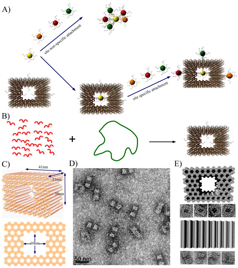
Here we demonstrate the application of spatially addressable, self-assembling DNA origami nanocages to encapsulate gold nanoparticles and interrupt the symmetry of their surface (Figure 1). DNA origami is a technique in which a long, single strand of genomic DNA is folded into a variety of predesigned shapes through the direction of approximately 250 short, staple strands.[8-17] Due to the unique sequence of each staple strand, DNA origami structures possess addressable binding sites with ∼ 6 nm resolution and have been utilized as templates to direct the assembly of metal nanoparticles, carbon nanotubes and biological materials.[18-29] Figure 1B and C illustrate the design and dimensions of the DNA origami cage. The structure is based on the honeycomb lattice design demonstrated by Shih and co-workers[9], with modifications that result in a 10 nm × 10 nm (cross section) inner cavity, an ideal size for the encapsulation of nanoparticles. Specifically, the cage contains 124 parallel helices; the length of each is ∼6 full helical turns with two crossovers connecting adjacent helices. The outer dimensions of the cage are 41 nm × 24 nm × 21 nm, with inner cavity dimensions of 10 nm × 10 nm × 21 nm. (see supporting information for details of the design, strand sequences and experimental methods). To prevent end-to-end stacking, two thymine nucleotides were added to staples strands located at outer extremities of the helices. The DNA origami cage was annealed and subsequently purified using agarose gel electrophoresis (a typical gel image is shown in Fig. S1) and after using uranyl formate for negative-staining, transmission electron microscopy (TEM) was used to visualize the purified DNA origami cage. TEM images (Fig. 1D) confirm the formation of DNA origami cages with nearly 100% yield, and reveal that the structures adopt one of two possible orientations when deposited onto the TEM grid (Fig. 1E).
Figure 1.
Schematic diagrams and TEM images of DNA origami cages. A) Schematics illustrating the challenge of assembling discrete nanoparticle architectures with site selective functionalization of the spherical nanoparticle surface. B) The formation of a DNA origami cage using short staple strands (red) to direct the folding of single stranded M13 DNA (green loop). Single stranded capture strands extend in or out of the DNA cage at specific positions. C) 3D and side view of the DNA origami cage, with 41 nm × 24 nm × 21 nm outer dimensions and 10 nm × 10 nm × 21 inner dimensions. D) Zoom out TEM image of a DNA origami cage (scale bar: 50 nm). E) Zoom in TEM images of DNA origami cages, displaying two different orientations.
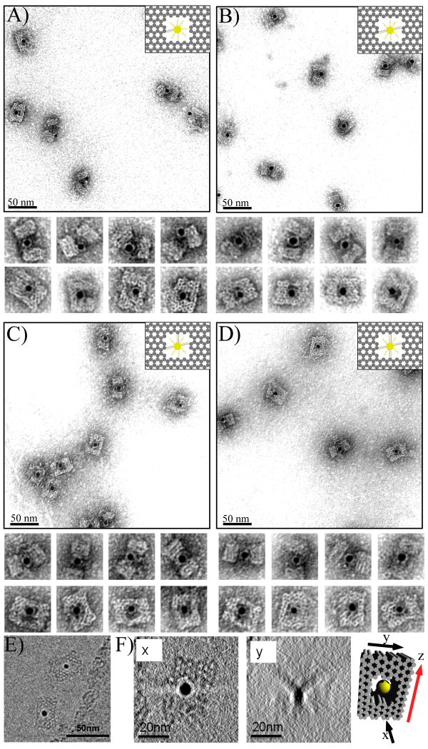
After verifying the nanocage had formed, the encapsulation ability of the cage was tested using 5 nm, spherical AuNP. The surfaces of AuNPs were covered with ssDNA (15 nucleotides in length) that was designed to hybridize with complementary probes displayed on the inner surface of the origami cage cavity. To compare the capture efficiency of 5 nm AuNP inside and outside of the cage, a single capture strand (15-nt ssDNA: 5′-AAAAAAAAAAAAAAA-3′) was projected from both surfaces (Fig. 2A and Fig. S11). DNA cages (containing capture probes) were prepared by mixing the capture strand (purified by PAGE) with the M13 scaffold and unpurified staples strands with a 1:1:10 ratio, and subsequently annealing the mixture (see SI for experimental methods). 5 nm AuNPs (covered with ssDNA complementary, see SI for detailed information) were mixed with the preassembled cages with a ratio of 1:2.5, and slowly annealed from 40°C. DNA cages with captured NPs were then purified by agarose gel electrophoresis and imaged by TEM (Figure 2A, S4, and S14).
Figure 2.
(A-D) TEM images of DNA cages with 5 nm AuNPs inside, encapsulated using different numbers of capture strands. (A) one; (B) two; (C) three; and (D) four capture strands. The samples were negatively stained with uranyl formate to improve the imaging contrast. (E) A typical cryo-EM image without negative stain showing the DNA cage with a 5 nm AuNP encapsulated inside. (F) The Z projections of the complete reconstructed cryo-EM tomogram from two different views. Planes x and y correspond to the black arrows shown on the model to the right; x corresponds to the top view easily seen in the un-tilted micrograph, while y is the face coming into view as the sample is tilted. The bold red arrow shown on the model indicates the rotation axis.
Analysis of TEM images reveals that AuNPs are captured by single probes located on the outside cage surface with a much higher efficiency (> 90%) than probes placed on the inside of cages (∼36%). The lower efficiency of inner encapsulation may be due to the increased steric hindrance and limited space within the cavity. A strong, electrostatic repulsion between the DNA-AuNP conjugate and the inside walls of the DNA cage will also affect the efficiency of AuNP loading. The images show that a single probe does not hold the AuNP exactly in the center of the cavity and most of the AuNPs can be seen close to the opening of the channel, especially when viewed from the side (see additional images in Fig. S4).
To improve the encapsulation efficiency of the inner cavity, several (2-4) capture probes were added to the inner surface. When two capture strands were added to opposing, inner cavity walls, the loading efficiency increased dramatically to ∼98% and nanoparticles were fixed in the center of the cage more often (Fig. 2B). When three or four capture strands were extended from various inner faces, 5 nm AuNPs were firmly anchored in the center of the cavity with loading efficiencies reaching nearly 100% (Fig. 2C and 2D). Based on these results, three inner capture probes were utilized for all subsequent experiments described below. Cryo-EM imaging (without negative staining) was used to reconstruct a 3D tomogram of the DNA cage containing a 5 nm AuNP. Figure 2E shows an example of the cryo-EM image and Figure 2F shows Z projections of the completely reconstructed tomogram from two different views of the structure, further verifying its 3D geometry.
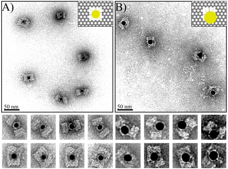
The ability of the nanocage to discriminate between nanoparticles of various sizes was tested; 10 and 15 nm AuNPs with the same ssDNA on their surface were synthesized and used for study. We anticipated that the 10 nm AuNP would encounter some degree of steric hindrance, but would ultimately be encapsulated, and the 15 nm AuNP would be too large to fit within the cavity. The 10 nm AuNPs were successfully encapsulated by the cage with ∼93% efficiency (slightly lower than for 5 nm AuNPs) and most particles were fixed in the center of the cavity (Fig 3A and S8). The lower yield is reasonable because 10 nm AuNPs that are covered with 15 nucleotide long ssDNA have an expected hydrodynamic diameter > 10 nm, resulting in a significantly crowded inner cavity. TEM images also show that for 10 nm nanoparticles, the cage is subject to a certain degree of deformation as a result of the relative dimensions of the cavity and the particle, especially when viewed from the side. However, the DNA cage structure possesses enough mechanical flexibility to accommodate a foreign object with slightly larger dimensions than the inner cavity.
Figure 3.
TEM images of DNA cages encapsulating 10 nm and 15 nm AuNPs using three capture DNA strands. (A) 10 nm AuNP; (B) 15 nm AuNP. The samples were negatively stained with uranyl formate before imaging.
When the cage was loaded with 15 nm AuNPs, the encapsulation efficiency was reduced to 68% (Fig. 3B and S9). To accommodate the larger size AuNPs, the DNA cage had to undergo severe deformation and the TEM images illustrate how 15 nm particles are generally located at one end of the cage with most of the particle surface still exposed to the outside. Although 15 nm particles are too big to fit within the cavity, the relatively high yield of attachment is probably a result of displaying three capture strands inside the cage, providing a strong enough binding force to hold the AuNP and DNA cage together. TEM images reveal the intrinsic flexibility of DNA nanostructures that allows the cage to bend and make room for the large NP, responding to the external, enthalpic requirement to maximize the DNA hybridization.
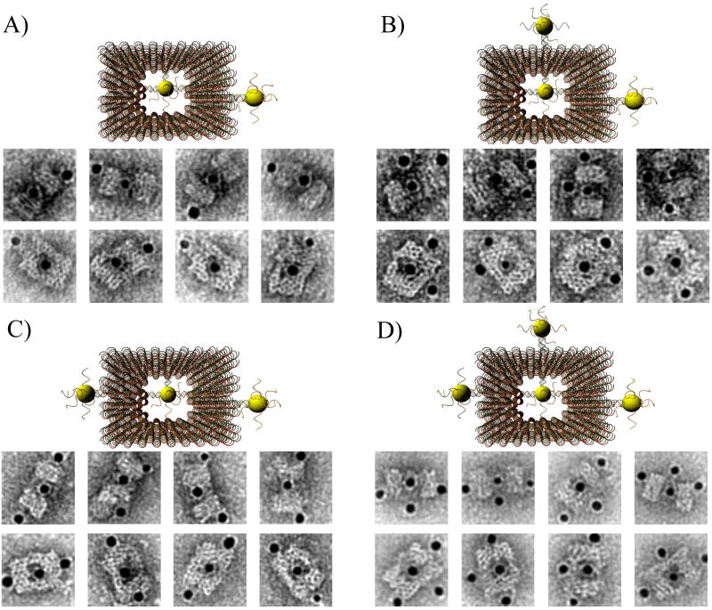
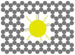
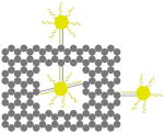
The outer surface of the DNA origami cage was modified with probes at addressable locations to capture other particles. We utilized this modification to demonstrate how the symmetry of a spherical nanoparticle surface can be broken; a 5 nm AuNP was encapsulated inside the DNA origami cage and a discrete number of 5 nm AuNPs were attached to defined positions on the outside surface of the cage. To achieve this, single stranded capture probes were incorporated at unique sites on the outer surface of the cage and 5 nm AuNPs, functionalized with sequences complementary to the capture strands, were recruited. The molar ratio between the origami cage containing the particle inside and the external particle is 1:3. The assembled structures were purified by gel and imaged using TEM. Figure 4A shows a DNA cage containing a 5 nm AuNP inside, and a separate 5 nm AuNP outside. The yield of fully assembled structures with AuNPs inside and outside is ∼85%. Additional AuNP structures with unique geometries were produced when cage structures with 5 nm AuNPs encapsulated inside were modified at various positions on the outside surface with two or three 5 nm AuNPs. The TEM images shown in Fig. 4B, C and D demonstrated designs with 90° and 180° between the particles, with formation efficiencies of ∼80%, ∼84% and ∼37% respectively. Table 1 summarizes the AuNP loading efficiency for all the constructs described here.
Figure 4.
TEM images of DNA cages with one 5 nm AuNPs inside, and various numbers of 5 nm AuNPs outside. The samples were negatively stained with uranyl formate before imaging.
Table 1.
The efficiency of DNA cage-AuNP structure assembly.
| structure | 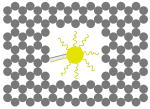 |
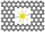 |
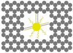 |
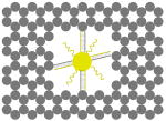 |
 |
| loading efficiency | 36.2% | 97.9% | 96.9% | 99.5% | 92.7% |
| structure | 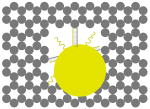 |
 |
 |
 |
 |
| loading efficiency | 67.8% | 85.1% | 80.0% | 84.3% | 36.7% |
In conclusion, we have demonstrated the ability of a DNA origami nanocage to encapsulate gold nanoparticles of various sizes. The spatially addressable surface of the DNA origami capsule presents an opportunity to interrupt the symmetry of spherical nanoparticles and provides a platform for further functionalization. Recently, Sleiman and co-workers constructed a DNA nanotube with alternating larger and smaller capsules for the size-specific encapsulation of gold nanoparticles (AuNPs), with selective release of the particles in response to externally supplied DNA. [30] By integrating the above strategies, the programmability of DNA cages and tube constructs can be utilized for a wide variety molecular encapsulation and release tasks, such as site specific protein bioconjugation, which may lead to an artificial structural platform for engineering novel bio-inspired, biomimetic and biokleptic materials.
Footnotes
This work was supported by grants from ARO, ONR, NSF, NIH, DOE and Sloan Research Fellowship to H.Y. H.Y. and Y. L. are supported as part of the Center for Bio-Inspired Solar Fuel Production, an Energy Frontier Research Center funded by the U.S. Department of Energy, Office of Science, Office of Basic Energy Sciences under Award Number DE-SC0001016. Some of the work presented here was conducted at the National Resource for Automated Molecular Microscopy, which is supported by NIH though the National Center for Research Resources' P41 program (RR17573). We thank C. Potter, B. Carragher and Anchi Cheng for helpful discussion and technical advice on the electron tomography work. We acknowledge the use of the EM facility in the School of Life Sciences at Arizona State University. We thank Jeanette Nangreave for proof-reading the manuscript.
Contributor Information
Zhao Zhao, Department of Chemistry and Biochemistry & The Biodesign Institute, Arizona State University, Tempe, AZ 85297, USA.
Erica L. Jacovetty, National Resource for Automated Molecular Microscopy, The Scripps Research Institute, La Jolla, CA 92037, USA
Prof. Yan Liu, Email: yan_liu@asu.edu, Department of Chemistry and Biochemistry & The Biodesign Institute, Arizona State University, Tempe, AZ 85297, USA.
Prof Hao Yan, Email: hao.yan@asu.edu, Department of Chemistry and Biochemistry & The Biodesign Institute, Arizona State University, Tempe, AZ 85297, USA.
References
- 1.Zanchet D, Micheel CM, Parak WJ, Gerion D, Alivisatos AP. Nano Letters. 2001;1:32–35. [Google Scholar]
- 2.Zanchet D, Micheel CM, Parak WJ, Gerion D, Williams SC, Alivisatos AP. J Phys Chem B. 2002;106:11758–11763. doi: 10.1021/ja017822w. [DOI] [PubMed] [Google Scholar]
- 3.Sperling RA, Pellegrino T, Li JK, Chang WH, Parak WJ. Adv Funct Mater. 2006;16:943–948. [Google Scholar]
- 4.Huo FW, Lytton-Jean AKR, Mirkin CA. Adv Mater. 2006;18:2304–2306. [Google Scholar]
- 5.Xu XY, Rosi NL, Wang YH, Huo FW, Mirkin CA. J Am Chem Soc. 2006;128:9286–9287. doi: 10.1021/ja061980b. [DOI] [PMC free article] [PubMed] [Google Scholar]
- 6.Devries GA, Brunnbauer M, Hu Y, Jackson AM, Long B, Neltner BT, Uzun O, Wunsch BH, Stellacci F. Science. 2007;315:358–361. doi: 10.1126/science.1133162. [DOI] [PubMed] [Google Scholar]
- 7.Maye MM, Nykypanchuk D, Cuisinier M, Van der Lelie D, Gang O. Nature Materials. 2009;8:388–391. doi: 10.1038/nmat2421. [DOI] [PubMed] [Google Scholar]
- 8.Rothemund PWK. Nature. 2006;440:297–302. doi: 10.1038/nature04586. [DOI] [PubMed] [Google Scholar]
- 9.Douglas SM, Dietz H, Liedl T, Hogberg B, Graf F, Shih WM. Nature. 2009;459:414–418. doi: 10.1038/nature08016. [DOI] [PMC free article] [PubMed] [Google Scholar]
- 10.Andersen ES, Dong M, Nielsen MM, Jahn K, Subramani R, Mamdouh W, Golas MM, Sander B, Stark H, Oliverira CLP, Pedersen JS, Birkedal V, Besenbacher F, Gothelf KV, Kjems J. Naure. 2009;459:73–77. doi: 10.1038/nature07971. [DOI] [PubMed] [Google Scholar]
- 11.Ke Y, Sharma J, Liu M, Jahn K, Liu Y, Yan H. Nano Letters. 2009;9:2445–2447. doi: 10.1021/nl901165f. [DOI] [PubMed] [Google Scholar]
- 12.Kuzuya A, Komiyama M. Chem Commun. 2009:4182–4184. doi: 10.1039/b907800b. [DOI] [PubMed] [Google Scholar]
- 13.Ke Y, Douglas SM, Liu M, Sharma J, Cheng A, Leung A, Liu Y, Shih WM, Yan H. J Am Chem Soc. 2009;131:15903–15908. doi: 10.1021/ja906381y. [DOI] [PMC free article] [PubMed] [Google Scholar]
- 14.Dietz H, Douglas SM, Shih WM. Science. 2009;325:725–730. doi: 10.1126/science.1174251. [DOI] [PMC free article] [PubMed] [Google Scholar]
- 15.Liedl T, Högberg B, Tytell J, Ingber DE, Shih WM. Nature Nanotechnology. 2010;5:520–524. doi: 10.1038/nnano.2010.107. [DOI] [PMC free article] [PubMed] [Google Scholar]
- 16.Han D, Pal S, Liu Y, Yan H. Nature Nanotechnology. 2010;5:712–717. doi: 10.1038/nnano.2010.193. [DOI] [PMC free article] [PubMed] [Google Scholar]
- 17.Liu W, Zhong H, Wang R, Seeman NC. Angew Chem Int Ed. 2010 doi: 10.1002/anie.201005911. Early View. [DOI] [Google Scholar]
- 18.Ke Y, Lindsay S, Chang Y, Liu Y, Yan H. Science. 2008;319:180–183. doi: 10.1126/science.1150082. [DOI] [PubMed] [Google Scholar]
- 19.Maune HT, Han SP, Barish RD, Bockrath M, Goddard WA, III, Rothemund PWK, Winfree E. Nature Nanotechnology. 2010;5:61–66. doi: 10.1038/nnano.2009.311. [DOI] [PubMed] [Google Scholar]
- 20.Rinker S, Ke Y, Liu Y, Yan H. Nature Nanotechnology. 2008;3:418–422. doi: 10.1038/nnano.2008.164. [DOI] [PMC free article] [PubMed] [Google Scholar]
- 21.Hung AM, Micheel CM, Bozano LD, Osterbur LW, Wallraff GM, Cha JN. Nature Nanotechnology. 2010;5:121–126. doi: 10.1038/nnano.2009.450. [DOI] [PubMed] [Google Scholar]
- 22.Viogt NV, Torring T, Rotaru A, Jacobsen MF, Ravnsbaek JB, Subramani R, Mamdouh W, Kjems J, Mokhir A, Besenbacher F, Gothelf KV. Nature Nanotechnology. 2010;5:200–203. doi: 10.1038/nnano.2010.5. [DOI] [PubMed] [Google Scholar]
- 23.Ding B, Deng Z, Yan H, Cabrini S, Zuckermann RN, Bokor J. J Am Chem Soc. 2010;132:3248–3249. doi: 10.1021/ja9101198. [DOI] [PubMed] [Google Scholar]
- 24.Pal S, Deng Z, Ding B, Yan H, Liu Y. Angew Chem. 2010;122:2760–2764. doi: 10.1002/anie.201000330. [DOI] [PubMed] [Google Scholar]; Angew Chem Int Ed. 2010;49:2700–2704. doi: 10.1002/anie.201000330. [DOI] [PubMed] [Google Scholar]
- 25.Numajiri K, Yamazaki T, Kimura M, Kuzuya A, Komiyama M. J Am Chem Soc. 2010;132:9937–9939. doi: 10.1021/ja104702q. [DOI] [PubMed] [Google Scholar]
- 26.Endo M, Katsuda Y, Hidaka K, Sugiyama H. J Am Chem Soc. 2010;132:1592–1597. doi: 10.1021/ja907649w. [DOI] [PubMed] [Google Scholar]
- 27.Gu H, Chao J, Xiao SJ, Seeman NC. Nature. 2010;465:202–205. doi: 10.1038/nature09026. [DOI] [PMC free article] [PubMed] [Google Scholar]
- 28.Lund K, Manzo AJ, Dabby N, Michelotti N, Johnson-Buck A, Nangreave J, Taylor S, Pei R, Stojanovic MN, Walter NG, Winfree E, Yan H. Nature. 2010;465:206–210. doi: 10.1038/nature09012. [DOI] [PMC free article] [PubMed] [Google Scholar]
- 29.Sacca B, Meyer R, Erkelenz M, Kiko K, Arndt A, Schroeder H, Rabe KS, Niemeyer CM. Angew Chem Int Ed. 2010 doi: 10.1002/anie.201005931. Early View. [DOI] [PubMed] [Google Scholar]
- 30.Lo P, Karam P, Aldaye F, Hamblin G, Cosa G, Sleiman HF. Nature Chemistry. 2010;2:319–328. doi: 10.1038/nchem.575. [DOI] [PubMed] [Google Scholar]


