Abstract
MRI scanner and magnetic resonance (MR)-compatible robotic devices are mechatronic systems. Without an interconnecting component, these two devices cannot be operated synergetically for medical interventions. In this paper, the design and properties of a graphical user interface (GUI) that accomplishes the task is presented. The GUI interconnects the two devices to obtain a larger mechatronic system by providing command and control of the robotic device based on the visual information obtained from the MRI scanner. Ideally, the GUI should also control imaging parameters of the MRI scanner. Its main goal is to facilitate image-guided interventions by acting as the synergistic component between the physician, the robotic device, the scanner, and the patient.
Keywords: Image-guided interventions (IGI), MRI, surgical robotics
I. Introduction
THE FIELD of interventional radiology makes use of different medical imaging modalities for specific types of operations. For example, ultrasound is used for biopsies in shallow areas such as the neck, catheter placement is done under X-ray, RF ablations in organs like kidneys and bones are accomplished with computerized tomography (CT), and cardiovascular interventions with MRI.
In the common interventional setup, the physician and the patient are placed near the imaging device. The operation is conducted by the radiologist based on the information obtained from the scanner. The radiologist needs to continuously manipulate the patient, the imaging scanner, and the interventional tip (e.g., RF ablator, biopsy needle). This constant physical and mental effort, in addition to being exposed to harmful radiation in the case of X-ray-based imaging modalities, is detrimental to both the physician and the patient. Moreover, with fatigue comes the difficulties for the physician and the lowering of comfort level of the patient that can lead to a longer period of recovery.
In the surgical field, these issues are addressed by using surgical robotic systems [1] that can accomplish minimally invasive or open surgery. The surgeon operates by handling haptic interfaces that command the surgical instrument tips while seated in a relatively comfortable position at the console of the robotic system couple of meters away from the patient. The actions are based on the visual information coming from the camera(s) inserted with the instruments through the incision area. The fatigue is reduced and the focus is improved since the surgeon is concentrated on the area of operation.
The translation of robotic-assisted surgery to interventional radiology is done by replacing the cameras with imaging devices. The main advantage of imaging modalities is the ability to “see” deep inside the tissue with possible enhancement of different characteristics. From a robotics point of view, the vision component of the system is the imaging device, e.g., the MRI scanner. There are several magnetic resonance (MR)-compatible organ-specific robotic devices that are already in existence [2]-[5]. An unconventional open MRI structure in the shape of a double donut [6] was specifically designed for the larger physical space it provides to conduct robot-assisted surgeries.
Although from an engineering point of view all the components of an interventional device are important, it is only through the graphical user interface (GUI) that the physician interacts with the system to command and control the operation. Therefore, the GUI is the central piece and is crucial for the intervention. As such, investigating the design guidelines of the GUI, which were not emphasized sufficiently in the existing literature, constitutes one of the objectives of this study.
From a mechatronic perspective, the robotic devices are classical examples of mechatronic systems. When examined closely, the same can be concluded about MR scanners. At the heart of mechatronics lays the synergistic mentality of integrating different parts, components, and devices of various forms and functions in order to construct a system that will accomplish the tasks at hand by working harmoniously. Although the area of mechatronics is based on an integrated design approach from scratch, inevitably, mechatronic systems sometimes must be build with the introduction of synergistic hardware and/or software components from the existing devices. The integration of an MR-compatible robotic device with the MRI scanner is a mechatronic design process in these lines. The GUI has a special role by its design flexibility in bringing together existing components to form a new system.
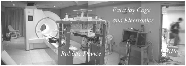
Economically it does not make too much sense to modify the design of MR scanners to suit the needs of robotic interventions because of the widespread use of MRI scanners with established open or closed bore designs. This issue was noticed with the interventional system [6] that necessitated the design of a new type of MRI scanner placing the surgeon in between the two bores. In the case of the robotic device used as the example in this paper [7], the design was created optimally in the mechatronic sense to operate inside a cylindrical closedbore MRI scanner (Figs. 1 and 2). The hardware design for the robotic device evolved for compatibility with the closed gantry MR scanner since the design of the latter was immutable due to the simple economic reason mentioned before. The adaptation of the robotic device to the existing scanner types increases its availability. The possibility of such an adaptation relies on the ability of the system to command and control the robotic device away from the closed bore gantry. Since the physician cannot be near the patient inside the gantry, it is the GUI that brings the area of interest to the focus of the physician.
Fig. 1.
Setup for the MR-guided robotic operation.
Fig. 2.
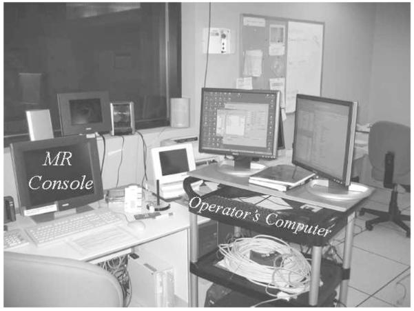
Operator’s computer next to MR console. Both computers are currently necessary to command and control the robot and to define the imaging parameters, respectively. In the future, the imaging parameters will be completely entered through the operator’s computer taking over the MR console’s responsibility. An observer looking through the glass window behind the MR console will see the setup shown in Fig. 1.
II. MRI Scanner and MR-Compatible Robotic Device as Mechatronic Systems
The operation of an MRI scanner is based on the physical principles of nuclear magnetic resonance [8], [9]. The fundamental function of the MR scanner is to place the subject inside astrong magnetic field. The images are obtained with precisely timed events of application of radio frequency pulses, magnetic field gradients using special coils and amplifiers, and several stages of digital-to-analog conversion (DAC) both for collection of data and controlling different components of the system. The raw data are the Fourier transform of the density of the atomic particle under observation. This is hydrogen for most of the medical applications.
All the procedures described above require synergetic operation of several different components of the scanner, such as RF amplifiers, gradient amplifiers, and analog-to-digital converters with precise timing. An embedded computer that runs a realtime operating system implements desired actions. By the fact that different devices, electronic systems, sensors, mechanical parts (the subject is introduced to the scanner using a moving table), computers, and software are integrated under a single roof, the MRI scanner is a mechatronic system [10], [11].
Robotic manipulators are classical examples of mechatronic devices. It is not unusual for them to have a vision component that would guide the operations based on the information obtained. For an MR-compatible robotic system, the vision system is mainly the MRI scanner with the possible addition of MR-compatible cameras and/or any MR-compatible medical imaging modality (e.g., MR-compatible ultrasound devices, optical imaging, etc.) attached to the end-effector that will enhance and complete the information coming from the MR scanner.
As the robotic device must operate inside the gantry of the MRI scanner, the mechatronic design takes into account the minimization of the effects of both devices on each other. The 7-DOF robotic device shown in this paper is the prototype that was built at Washington University (see Figs. 1 and 2). The reader is referred to earlier work for detailed information about the MR-compatible design, construction, and performance of the device [7], [12]-[15]. The software component of the device including the GUI is build in Matlab (Mathworks, Natick, MA).
III. Integrating the Robotic Device and the MRI Scanner
Under regular imaging procedures (no robotic intervention), the operator interacts with the scanner by using the MR console shown on the left sides of Figs. 2-4. The parameters for imaging, such as orientation, field of view, and the number of slices, pulse sequence timing parameters (to emphasize different tissue properties) are entered via the MR console before the study starts.
Fig. 4.
Setup for the MR-guided robotic operation [16].
With MRI, slices of human body can be imaged in any orientation and centered in any location at a reasonable distance from the gantry’s center. This capability of visualizing internal organs makes the modality an excellent choice for real-time interventions since they require quick, precise, and safe access to the target area.
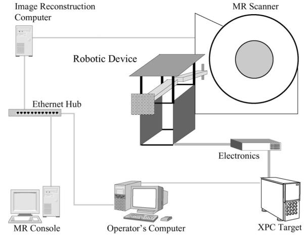
After the patient is introduced to the gantry, the operator interacts with the scanner through the MR console. The embedded computer well hidden inside the MR scanner (see Fig. 3) coordinates the events of the pulse sequence that will first result in raw data (Fourier transform of the weighted nucleus density) that is kept temporarily in the embedded computer’s memory before the completion of the acquisition. After the acquisition, the raw data are transferred to the image reconstruction computer (Fig. 4). Afterwards, the data, which arrive with headers containing information about the position and orientation of the slices, are discrete Fourier transformed to obtain the images.
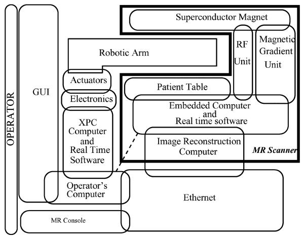
Fig. 3.
Description of the interconnected devices forming the mechatronic system. The operator interacts with the GUI. Dashed line indicates possible direct connection in future with the embedded MR scanner computer to speed up data retrieval.
From a technical point of view, in a clinical setup, what happens following the collection and (fast) Fourier transforming of the data is the conversion of the images to Digital Imaging and Communications in Medicine (DICOM) format along with the slice and patient information in order to preserve and investigate the images. The images can be seen or printed anytime after the scans are completed by a physician using the DICOM database. The computation of the images and the maintenance of the database are the responsibility of the image reconstruction computer and the MR console (see in Fig. 4). This is very useful for clinical purposes and reviewing the patient’s file later in time but not necessarily a helpful setup for interventional purposes because the visual information obtained from the MR scanner must be used immediately in the interventional procedure to command and control the robotic device inside the scanner. Clearly, the time that elapses between the collection of data, image reconstruction, and database update to be able to see the images on the MR console is unacceptable for real-time interventional purposes. In fact, this point is essential to the mechatronic integration of both systems for completing the intervention procedure as quickly as possible. In any interventional framework, the information must be made available as fast as possible to the operator. To overcome the time delay, a direct connection between the operator’s computer and the image reconstruction computer must be used (see Fig. 4). Although a direct connection to the scanner’s computer (dashed line in Fig. 3) would be the fastest way to obtain the raw data from the system, such a setup can cause delays in the scanner operation and disrupt image acquisition. Thus, it is safer to retrieve the data from the image reconstruction computer after the acquisition is completed. On the other hand, it is practically impossible to integrate robot planning and visualization into the MR scanner’s console without the assistance of the scanner manufacturers. For these reasons, a dedicated interventional GUI running outside the MR console lies at the heart of the setup until the proof of concept is achieved. The GUI collects the images from the scanner and presents them to the operator. It obtains an acceptable placement of the robotic device in virtual reality and sends signals to the real-time computer to place the robot physically for the intervention.
In brief, the GUI is the center synergistic component that provides the mechatronic integration of the robotic device with the MRI scanner.
Fig. 3 describes the the structure of the overall mechatronic system obtained by integrating the robotic device and the MRI scanner. Figs. 1 and 2 show the physical placement of the scanner and the robotic device. Fig. 4 describes schematically how the systems are interconnected. The GUI and the MR scanner console are the only interfaces (with the exception of the haptic devices and possible additional MR-compatible vision components) that the operator interacts during the intervention, as shown in Fig. 3. Ideally, slice planning should be done from the GUI by using direct communication with the scanner’s embedded computer. One more time, this requires a complete modification of the existing MR console in order to accommodate new functions required for the command and control of the robot. This path is against the mentality of designing the robotic device around the MR scanner and can only be economically viable with the participation of the MR scanner manufacturers.
IV. General Setup and the Gui
The basic idea of the system is described in Fig. 5. The patient is placed in the scanner along with the robot and the slices of interest are imaged using the scanner. Different stages before and during operation are described later in this section.
Fig. 5.
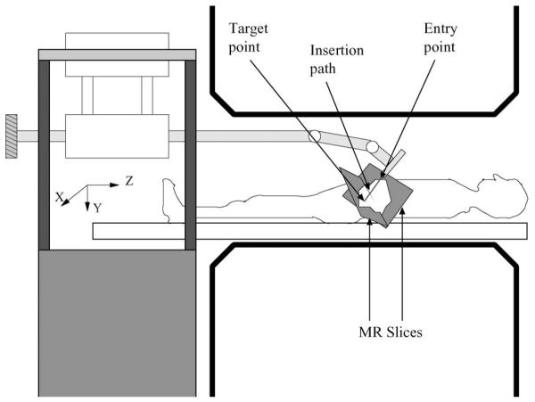
Position of the patient and the robot inside the MRI scanner and the coordinate frame. The MR slices are representative of the location of the images [16]. The strong magnetic field is in the z-direction.
A. Coordinate Frame Alignment
The very first step after the placement of the patient and the robotic device inside the scanner is the alignment of the robotic coordinate frame with the scanner coordinate frame where all the images are physically described. This step is crucial for the whole operation since the physical placement of the robot depends on the coordinate frame. In the system of this paper, the alignment is accomplished by using a fiducial (a cross) marker filled with gadolinium attached to the arm in known robotic frame coordinates. First the GUI is set to the special alignment mode, then the robot arm is held parallel to the ground that equates all the rotational joint variables to zero. A set of multislice images are taken and the fiducial marker is located. Subsequently, two orthogonal slices that contain the fiducial marker are obtained and shown on the GUI’s 2-D windows (see Section IV-C for a detailed description of the GUI). GUI markers are moved automatically (via image processing methods) or manually on the images of the fiducial marker location to discover its scanner coordinates. Once marker coordinates are known in both frames and since the cartesian frames are parallel, the translational vector that describes the conversion is obtained from the fiducial marker coordinates in both frames. Note that the coordinate frame alignment is highly dependent on the geometry of the robotic device.
B. Preoperative Stage
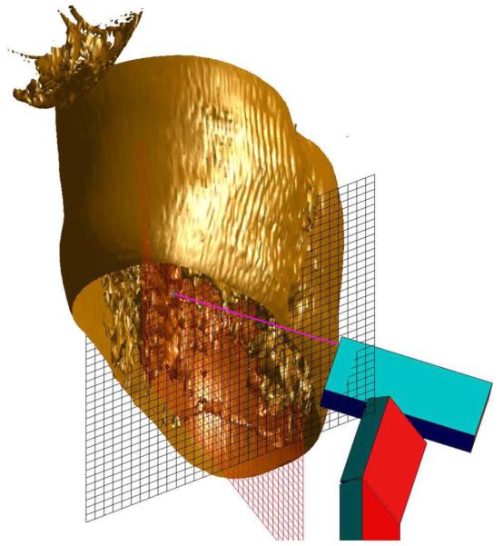
Before the intervention starts, an important task is the geometric assessment of the area of operation. As the intervention will be based on the MR images, the first step is to determine an appropriate positioning and location of the slices. The operators might want to make decisions in a 3-D virtual environment displaying the region of operation. A series of preoperative images can be taken to build a virtual 3-D reconstruction (see Fig. 6). To draw the 3-D volume set, a couple of steps are necessary. Although the acquisition and transfer of the data from the MR scanner is the same as described in the next section, there are surface reconstruction algorithms that need to run on the multislice set once the data are transferred to the operator’s computer and Fourier transformed to obtain the images. For this reason, the GUI has a dedicated preoperative planning button that starts the procedure. The 3-D volume data are acquired by using either a multislice set or a true 3-D pulse sequence. The decision is made based on the speed and resolution constraints. Once the images are obtained, the 3-D surface is reconstructed using standard algorithms for isosurface construction included in Matlab. The isovalue that defines the surface is chosen depending on the desired enhancement of the target area. Any image processing routine, such as edge detection, segmentation, and classification, that is deemed relevant for better target acquisition can be applied to the set. Visual aids, for example, the orthogonal grid of Fig. 6 can be placed initially to guide the position of the robot and to have an idea about the dimensions of the area of interest. Following the decision about the interventional path using the 3-D virtual environment, the position and orientation of the slices can be finalized.
Fig. 6.
3-D reconstruction for preoperative planning in the thoracic area.
C. Interventional Stage
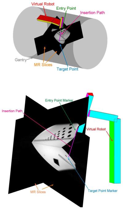
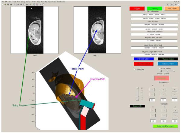
After the preoperation planning is finished, the intervention can start. The idea is to obtain two oblique (see Fig. 7) or parallel (see Fig. 8) slices and display them on the GUI appropriately for the intervention. The raw data are transferred to the operator’s computer (Fig. 4) including the coordinates of the slices and the fast Fourier transform is computed to obtain the images. The images are presented with the GUI in two different fashions (see Fig. 8). First, 2-D images are shown in the windows placed on top of the GUI to decide about the entry and target point of the intervention. These windows are called slice windows. Second, another window, called 3-D window, provides a virtual presentation of the robot, of the gantry, and of the slices displayed in their physical positions. The image contrast on all images and the transparency of the 3-D slices can be adjusted using the buttons next to the 3-D window. If desired, preoperative 3D volume set can also be shown in the 3D window as in Fig. 8. In order to take full advantage of MRI’s oblique slice acquisition, the GUI’s 3-D window represents the oblique slices in a virtual environment. The view point of the environment can be rotated and tilted as desired for better apprehension of the area of interest.
Fig. 7.
Close up view of the slices and the virtual robot for different target and entry points. The operator can choose to display or not to display the gantry. The phantom is a water-filled cylinder with hollow tubes inside.
Fig. 8.
GUI that commands and monitors the operations. For a close up view of the 3-D portion, see Fig. 7. Notice the difference at the boundaries with the 3-D set and MR slices due to breathing. The functions of the different buttons are explained in the text.
Each of the slice windows (Fig. 8) is associated with a marker. The first window displays the entry point marker and the second displays the target point marker. Using the mouse, the operator can move any of these points in order to decide about the best insertion path for the intervention. The markers are also shown in the 3-D environment on their respective locations on the slices. As soon as any of the points is moved in the slice windows, the markers in 3-D follow the motion of their 2-D counterparts. The virtual robot in the 3-D window positions itself inline with the insertion path defined by the entry and the target point. This is accomplished by solving the inverse kinematics of the robot [17]. This mode of operation is called automatic placement. The virtual environment provides a comfortable framework for executing the intervention. As the calculations are finished rapidly and the graphics are updated quickly, the procedure has the feeling of a movie or a video game. A warning will be issued if the length of the needle or the probe is shorter than the insertion path.
The operator is not restricted to using the markers to actuate the manipulator. Basically, by using the buttons and/or the fields provided on the right-hand side of the GUI, the operator can actuate any joint or DOF to any allowable value. This mode of operation is called manual placement. Note that in the manual mode, it is very difficult for a human operator to place a 7-DOF robot in an appropriate position for an intervention.
These delicate placements can be achieved quickly using the zoom features for all the images as well as changing the angle of view by rotations and tilts for the 3-D window. Moreover, the 3-D window can be detached from the whole GUI and be opened on a separate window with zooming capabilities to have better assessment. This facilitates the intervention when the operator’s computer has dual monitors. On one monitor using 2-D images, target markers manipulations can be made while watching the position of the robot in the 3-D window that covers the whole second monitor. The virtual robot continues to follow commands in a separate window as it would when it was kept inside the GUI.
In addition, by using the real-time encoder data, the physical robot can also be monitored using the detached 3-D window when, for example, a haptic device is used for commanding the manipulator or after the robot is commanded to move physically to the desired position.
The operator also has the option of changing gantry’s transparency or not showing it at all (see Figs. 7 and 8) in order to obtain the best possible view(s). Moreover, whether the gantry is displayed or not, there exists a safety precaution in place that alerts the operator by displaying the gantry in orange if, for some reason, any of the extremities of the robot touch it.
It is quite possible that in the beginning of the operation, the interventional radiologist will not be satisfied with the position and the orientation of the slices in order to accomplish the intervention and would like to change them. Although currently slice positioning must be done using the MR console, there is work in progress in collaboration with Siemens engineers to modify the slice positions and orientations from the GUI [18].
The GUI provides a trigger button that sends a signal to the scanner to start the scans. Once the button is hit, a trigger pulse is sent to the MR scanner and the raw data are loaded and processed. In case imaging procedures are started from the MR console, by hitting the button “Load Images” on the GUI, the raw data that are held in the image reconstruction computer’s hard disk are loaded.
In addition to the graphics, the GUI also presents at any time numerical values of the slice positions and orientations, positions of the entry and target points, numerical values of the joint variables of the physical and virtual robot as well as their origin. By pushing the GUI button “Physical Robot,” the operator can also display the physical robot in the 3-D window in order to have an idea about the true physical position of the device.
There are two GUI-based modes of operation for the command of the robotic device. In the first one, only the virtual robot in the 3-D window is actuated based on automatic or manual placement. The changes are reflected to the physical robot after the operator decides that everything is in order. The operator can use the GUI button “Move the Robot” to send the commands to the physical robot for the execution of the move. Once the button is pressed, the motion of the physical robot is shown continuously in the 3-D virtual environment window for monitoring. This mode of command is called the planned mode that is preferable and safe. In the second mode, the commands obtained from the GUI in the automatic or manual placement mode are immediately dispatched to the physical robot. In this mode, called the online mode, extreme caution must be used.
In addition, the device can be commanded by using a haptic device and/or directly controlling the motors by using electrical switches. The GUI button “Manual Control” that puts the device into this mode does the following: it immediately disengages the feedback loop that controls the robot arm, starts collecting the motor encoder data in order to monitor numerical values of the joint variables, and continuously displays the physical robot on the 3-D virtual environment. If desired, the virtual environment can be shown using a projector inside the scanner room so that the operator can be near the patient and can guide the intervention using a haptic interface or an MR compatible computer near the scanner.
V. Conclusion and Future Directions
MRI provides many advantages compared to the other imaging modalities. The images can be obtained at different slice positions and orientations without moving the patient or the equipment. This is a tremendous flexibility and gain of speed in discovering the intervention path. Moreover, different tissue properties can be enhanced using specific pulse sequences, opening the way to a quick and thorough assessment of the operation’s success level. For example, in RF ablations under CT, the final step is to insert a temperature probe to the ablation area, and the temperature measurement is obtained from a point. MRI can provide a better evaluation by covering the whole area of interest using diffusion-sensitive MR images that are affected by tissue temperature [16]. There is also added advantage of eliminating harmful radiation for the patient and the medical crew. All these reasons make MR modality an excellent choice as an interventional vision component. Due to the high number and better image sensitivity, economically it makes more sense to use closed-bore MR scanners for robotic interventions.
From an engineering perspective, both the MR scanner and MR compatible robots are mechatronic devices. The component that brings them together is the GUI. Regardless of the specifics of the robot (structure, intended operation, and target organ) and the scanner (open or closed bore, special type), the GUI’s fundamental objective is to make the scanner, the robot, the physician, and the patient operate in synergy. Especially, since the closed-bore scanners are preferred, which means that it will be difficult to reach the patient inside the scanner, the GUI has to bring the area of operation in the focus of the physician. This approach will reduce the fatigue for the operator, and as the operation will be completed faster and in a more efficient manner, it will increase the comfort level of the patient similar to the situation in robotic surgery. One of the future aims after the satisfactory completion and testing of the prototype is defining emergency procedures in case there is a need to access the patient.
The GUI provides synergy by several additional means. First, it takes full advantage of MR-imaging properties by displaying in a 3-D virtual environment the slices with their positions and orientations for the assessment of the interventional path. The environment allows changing the point of view by rotations and tilts for the same goal. The addition of image processing algorithms such as edge detection and segmentation facilitates the target acquisition. Second, the GUI also has the possibility of showing preoperative 3-D volume data for planning. Third, the superimposition of the robotic device’s virtual representation to the 3-D environment serves two purposes. The first is an initial assessment of the robot position before any action is taken for possible corrections and preventive moves. This way, after the decision is made, the GUI should permit small manual adjustments of the device. The second purpose is the monitoring of the robot during the physical motion. This also opens the possibility of using a haptic device to control the robot inside the scanner room with the GUI projected on a large screen. Fourth, the GUI incorporates safety futures such as collision alerts with the gantry.
Ideally, to be in full synergy, slice and pulse sequence parameters should be controlled from the GUI. The MR console is already overloaded computationally with different tasks such as database management, patient registration, and constant communication with the scanner. For this reason, a dedicated GUI that commands and controls the intervention is the only feasible solution. One way of improving the setup is to build a communication line between the MR console and the GUI that can only be achieved with the assistance of scanner manufacturers [18].
In an interventional operation, all the available data must be presented to the physician as fast as possible, especially the images. The best solution would be to obtain the raw data from the MR scanner’s embedded computer and apply necessary mathematical transformations on a dedicated computer. Using DICOM protocol to get the images from the database is an unacceptably long process, and building a direct connection to the embedded computer to obtain the raw data would again require assistance of the manufacturers as well as Food and Drug Administration’s approval. A compromise is reached by obtaining the raw data from the image reconstruction computer. This approach is significantly faster than the DICOM path and does not alter any functions of the scanner’s embedded computer.
The GUI’s flexibility allows the easy incorporation of new additions and improvements. For example, if the mechanical design of the robot was to be changed, all that needs to be done is to update the inverse kinematics and the representation of the virtual robot.
Another possible future development is the incorporation of a flexible tip. Currently, the tip is assumed to be a straight line but using flexible ones curved interventional paths can be obtained. This technology will require new techniques that will localize the tip. As an example, miniature coils can be attached to the different points of the tip to see it using MRI and control it to define the path. It will also be necessary to build path definition algorithms with organ avoidance since it is harder to find a curved path manually. The implementation will require different image processing algorithms to define the organ boundaries. This is not a big challenge if the area of interest is stationary. Synchronizing the robot with patient motion is an important and difficult challenge that will require the design of new feedback control schemes, the addition of new sensors, and vision components to detect the motion externally. Internally, the image processing algorithms for organ detection must be predictive in time domain in order to compensate for the motion of the organs. This point can be improved with the discovery of faster pulse sequence techniques that should be combined with the algorithms. Finally, the GUI can be used to execute the operation from a remote location using the connection over the Internet or any appropriate communication link.
In conclusion, as it is almost impossible for one or several human operators to visualize an adequate path of intervention from images presented in two dimensions and to manually position a robotic device of several degrees of freedom according to that path, real-time IGIs with MR-compatible robotic devices are not conceivable without a synergistic GUI that ties all the mechatronic components and humans together.
Acknowledgment
The authors dedicate the manuscript to their parents, Ayla and Halil Özcan and Anna and Vasilios Tsekos.
This work was supported in part by the Washington University Small Animal Imaging Resource, a National Cancer Institute (NCI) funded Small Animal Imaging Resource Program facility (R24-CA83060) and in part by the National Institutes of Health (NIH) under Grant RO1HL067924 (magnetic resonance (MR) pulse sequences and real-time reconstruction hardware/software).
Biographies

Alpay Özcan (S’91–M’95–SM’06) received the B.S.E.E. degree and the B.S. degree in mathematics from Bogaziçi University, Istanbul, Turkey, in 1992 and 1994, respectively, the M.Sc. degree (with honors) in electrical engineering from Imperial College London, London, U.K., in 1993, and the M.S. degree and the D.Sc. degree in systems science and mathematics from Washington University, St. Louis, MO, in 1996 and 2000, respectively.
He was a Research Assistant and a Systems Administrator at Washington University. He is currently a Research Assistant Professor at the Biomedical Magnetic Resonance Laboratory, Mallinckrodt Institute of Radiology, Washington University School of Medicine, St. Louis. His current research interests include MRI, robotics, nonlinear systems, optimal control, power systems, image processing, computational techniques, probability, and stochastic analysis.

Nikolaos Tsekos (M’06) received the B.S. degree in physics from the National and Kapodistrian University of Athens, Athens, Greece, in 1989, the M.Sc. degree in physiology and biophysics from the University of Illinois at Urbana Champaign, in 1992, and the Ph.D. degree in biomedical engineering from the University of Minnesota, Minneapolis, in 1995.
He is currently an Assistant Professor of radiology and biomedical engineering at the Cardiovascular Imaging Laboratory, Mallinckrodt Institute of Radiology, Washington University School of Medicine, St. Louis, MO. His current research interests include cardiovascular and interventional MRI and, in particular, are focused on the development of dynamic MRI and MR-compatible robotic manipulators. His work has been funded by the National Institutes of Health (NIH), the Whitaker Foundation, the American Heart Association, and the Radiological Society of North America (RSNA).
Footnotes
Color versions of one or more of the figures in this paper are available online at http://ieeexplore.ieee.org.
Contributor Information
Alpay Özcan, Biomedical Magnetic Resonance (MR) Laboratory, Mallinckrodt Institute of Radiology, Washington University School of Medicine, St. Louis, MO 63110 USA (ozcan@zach.wustl.edu)..
Nikolaos Tsekos, Cardiovascular Imaging Laboratory, Mallinckrodt Institute of Radiology, Washington University School of Medicine, St. Louis, MO 63110 USA (tsekosn@mir.wustl.edu)..
References
- [1].The da Vinci surgical system. [Online] Available: http://davincisurgery.com.
- [2].Larson BT, Erdman AG, Tsekos NV, Koutlas IG. Design of an MRI-compatible robotic stereotactic device for minimally invasive interventions in the breast. J. Biomech. Eng. 2004;126:458–465. doi: 10.1115/1.1785803. [DOI] [PubMed] [Google Scholar]
- [3].Krieger A, Susil RC, Ménard C, Coleman JA, Fichtinger G, Atalar E, Whitcomb LL. Design of a novel MRI compatible manipulator for image guided prostate interventions. IEEE Trans. Biomed. Eng. 2005 Feb.52(2):306–313. doi: 10.1109/TBME.2004.840497. [DOI] [PMC free article] [PubMed] [Google Scholar]
- [4].Masamune K, Kobayashi E, Masutani Y, Suzuki M, Dohi T, Iseki H, Takakura K. Development of an MRI-compatible needle insertion manipulator for stereotactic surgery. J. Image Guided Surg. 1995;1:242–248. doi: 10.1002/(SICI)1522-712X(1995)1:4<242::AID-IGS7>3.0.CO;2-A. [DOI] [PubMed] [Google Scholar]
- [5].Hempel E, Fischer H, Gumb L, Hhn T, Krause H, Voges U, Breitwieser H, Gutmann B, Durke J, Bock M, Melzer A. An MRI-compatible surgical robot for precise radiological interventions. Comput. Aided Surg. 2003;8(4):180–191. doi: 10.3109/10929080309146052. [DOI] [PubMed] [Google Scholar]
- [6].Chinzei K, Hata N, Jolesz F, Kikinis R. MR compatible surgical assist robot: System integration and preliminary feasibility study; Proc. 3rd Int. Conf. Med. Robot., Imag. Comput. Assisted Surg.; Pittsburgh, PA. 2000.pp. 921–930. [Google Scholar]
- [7].Tsekos NV, Özcan A, Christoforou E. A prototype manipulator for magnetic resonance-guided interventions inside standard cylindrical magnetic resonance imaging scanners. J. Biomech. Eng. 2005 Nov.127(6):972–80. doi: 10.1115/1.2049339. [DOI] [PubMed] [Google Scholar]
- [8].Liang Z-P, Lauterbur PC. Principles of Magnetic Resonance Imaging: A Signal Processing Perspective. IEEE Press; Piscataway, NJ: 2000. [Google Scholar]
- [9].Haacke EM, Brown RW, Thompson MR, Venkatesan R. Magnetic Resonance Imaging: Physical Principles and Sequence Design. Wiley; New York: 1999. [Google Scholar]
- [10].Cetinkunt S. Mechatronics. Wiley; New York: 2007. [Google Scholar]
- [11].Silva CWD. Mechatronics: An Integrated Approach. CRC Press; Boca Raton, FL: 2004. [Google Scholar]
- [12].Christoforou EG, Tsekos NV, Özcan A. Design and testing of a robotic system for MR image-guided interventions. J. Intell. Robot. Syst. 2006 Oct.47(2):175–196. [Google Scholar]
- [13].Christoforou E, Özcan A, Tsekos NV. Manipulator for magnetic resonance imaging guided interventions: Design, prototype and feasibility; presented at the IEEE Int. Conf. Robot. Autom.; Orlando, FL. May 2006. [Google Scholar]
- [14].Christoforou E, Tsekos NV. Robotic manipulators with remotely-actuated joints: Implementation using drive-shafts and u-joints; presented at the IEEE Int. Conf. Robot. Autom.; Orlando, FL. May 2006. [Google Scholar]
- [15].Christoforou E, Akbudak E, Ozcan A, Karanikolas M, Tsekos NV. Performance of interventions with manipulator-driven real-time MR guidance: Implementation and initial in vitro tests. Magn. Reson. Imag. 2007 Jan.25(1):69–77. doi: 10.1016/j.mri.2006.08.016. [DOI] [PubMed] [Google Scholar]
- [16].Özcan A, Christoforou E, Brown D, Tsekos N. Fast and efficient radiological interventions via a graphical user interface commanded magnetic resonance compatible robotic device; Proc. 28th IEEE EMBS Annu. Int. Conf.; New York City. Aug. 30–Sep. 3, 2006; pp. 1762–1767. [DOI] [PMC free article] [PubMed] [Google Scholar]
- [17].Sciavicco L, Siciliano B. Modelling and Control of Robot Manipulators. 2nd ed. Springer-Verlag; New York: 2000. series Advanced Textbooks in Control and Signal Processing. [Google Scholar]
- [18].Akbudak E, Zuehlsdorff S, Christoforou E, Özcan A, Karanikolas M, Tsekos NV. Freehand performance of interventions with manipulator-driven real-time update of the imaging plane; ISMRM 14th Scientific Meeting; Seattle, WA: International Society for Magnetic Resonance in Medicine. May 2006. [Google Scholar]


