Abstract
Controlling droplet incubation is critical for droplet-based microfluidic applications; however, current techniques are either of limited precision or place strict limits on the incubation times that can be achieved. Here, we present a simple technique to control incubation time by exploiting close-packed plug flow. In contrast to other techniques, this technique is applicable to very short and very long incubation times.
Droplet-based microfluidic techniques can perform reactions at high throughput, generating billions of compartments per hour.1, 2, 3 Each droplet plays the role of a tiny “test tube,” in which an individual chemical or biological reaction is performed.4, 5, 6, 7 Of primary importance is controlling the incubation time of each drop: the time from the point of drop formation to when the drop is assayed to determine the reaction outcome. This is usually achieved by flowing the drops through a “delay line” of controlled dimensions at a controlled velocity.8 However, this approach is of limited precision due to the tendency of drops to flow at different rates through delay lines. In Poiseuille flow, the velocity of the fluid varies from zero at the channel walls to a maximum at its center; this causes the drop velocity to vary in relation to its position, resulting in a distribution of drop velocities and, thus, a distribution of incubation times. One way to increase precision is to maintain the drops single-file by flowing them through a narrow delay line; this prevents drops from exchanging position, resulting in a constant incubation time.8 However, this requires narrow delay lines with large hydrodynamic resistance, making it impractical for all but very short delays.9 Alternatively, a wide delay line can be used to reduce hydrodynamic resistance while increasing incubation time. For long delay lines, time dispersion can also be mitigated by allowing the drops to exchange positions many times. As this happens, variations in the droplet velocity average to zero, causing the average velocity to converge to the flow velocity, resulting in constant incubation time. The averaging can be accelerated by placing obstacles or constrictions10 in the flow, forcing the drops to change position more often. In this case, the average velocity converges as , where N is the number of obstacles traversed. This is effective at reducing time dispersion, but is only applicable to long delays, since the weak square-root dependence necessitates many obstacles before convergence. An optimal system would allow incubation time to be set precisely and uniformly for all drops; it would be applicable to short and long incubations.
In this paper, we present a simple and robust method to control incubation time. We create drops above the close-packing volume fraction of ϕc=0.64, calculated in the case of spheres randomly close-packed, so that the resultant emulsion is jammed.11 We confirm experimentally that a volume fraction above ϕc causes the drops to move as a plug rather than flow as a liquid; this results in a first-in, first-out flow of drops, and constant incubation time. We illustrate the effectiveness of this method by using it to measure the reaction kinetics of β-galactosidase accurately. We also demonstrate how to adjust the drop size at fixed volume fraction by varying the drop maker dimensions and total flow rate.
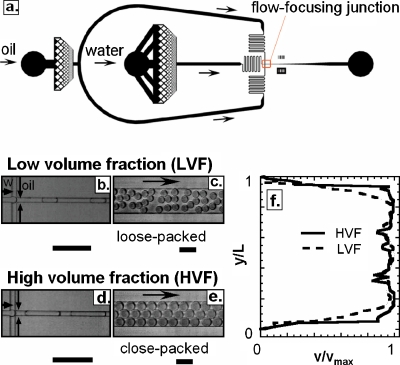
Time dispersion is a consequence of the nonuniform velocity profile in a microchannel.12 As a drop flows through a channel, its velocity can vary as it samples different streamlines. To investigate this hydrodynamic dispersion, we flow drops at different volume fractions through a poly(dimethylsiloxane) delay line. The droplet phase of the emulsion consists of distilled water and the continuous phase of HFE-7500 fluorocarbon oil with a PEG-triblock biocompatible surfactant at 1.8% by weight, provided by RainDance Technologies. The drops are made using microfluidic flow-focusing devices, with square cross-sectional dimensions varying from 8 to 50 μm; a schematic of a flow-focus device is shown in Fig. 1a. The flow-focus junction consists of a cross junction into which the water and oil phases are injected, shown for the low-volume fraction (flow rate ratio Qo∕Qa=2, packing ratio ϕ=0.33) and the high-volume fraction (Qo∕Qa=0.5, ϕ=0.67) cases in Figs. 1b, 1d, respectively, where Qo and Qa are the oil and the aqueous volumetric flow rates, respectively. After being formed, the drops enter a 15 μm tall and 200 μm wide incubation channel. In the low-volume fraction case, the drops are separated by gaps of oil, as shown in Fig. 1c. In movies of the flow, the drops move with respect to one another, resulting in a varying droplet velocity. By contrast, in the high-volume fraction case the drops are in contact, as shown in Fig. 1e. The close-packing prevents them from changing position and also causes them to move as a plug at constant velocity. To quantify drop motion in these two cases, we use a particle image velocimetry method to measure the velocity profile across the width of the channel, shown for both cases in Fig. 1f. In the low-volume fraction case the velocity varies across the channel, as shown by the dashed line; however, in the high-volume fraction case the velocity profile is constant, as shown by the solid line. Thus, by fixing the flow rate ratio resulting in ϕ>ϕc, the drops are made to flow at a constant velocity. Other volume fractions are shown in supplemental material Fig SI1.13
Figure 1.
(a) Schematic of flow-focus drop maker used to create drops. The flow-focus junction is indicated by the arrow and shown at higher magnification in (b) and (d). Images of drops flowing through a wide delay line for (c) low-volume fraction and (e) high-volume fraction emulsions. (f) Velocity profile across the delay line for both cases; y and L, respectively, represent the distance from one wall of the channel where the velocity is measured and the width of the channel. y∕L=0.5 corresponds to the center of the channel. The profile is more plug-like for the high-volume fraction emulsion than for the low-volume fraction emulsion due to close-packed plug flow. The scale bars denote 100 μm.
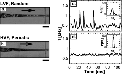
In many applications of droplet-based microfluidic techniques it is necessary to introduce premade drops into a device for additional processing and analysis, such as picoinjection,14 sorting,15 and optical detection.16 A benefit of close-packing is that drops can be introduced into devices at controlled intervals. This occurs because the drops naturally order to maximize their free volume,16 and this ordering gives rise to regular flow. To quantify this spacing between droplets, we produce droplets at the low-packing and close-packing ratio in a flow-focusing device, reinject them into another device using a tubing that connects both devices. After droplet spacing with oil, we measure their frequency of reemission. When the drops are at low-volume fraction they randomly disperse in the flow because they are not packed together, as shown in Fig. 2a; this causes them to enter at irregular intervals, leading to varying droplet emission frequency, as shown in Fig. 2c. By contrast, when close-packed the drops order, as shown in Fig. 2b, the droplet regularity, we measure the frequency probability distributions for both cases, plotted inset into Figs. 2c, 2d. The distribution is much narrower for the high-volume fraction case than for the low-volume fraction case, demonstrating that close-packing results in controlled droplet spacing.
Figure 2.
Images of (a) low-volume fraction and (b) high-volume fraction emulsions being reintroduced into a microfluidic device; the close-packing of the high-volume fraction emulsion causes the drops to organize into a regular array. Measurement of drop frequency at the spacing junction for (c) low-volume fraction and (d) high-volume fraction emulsions. The frequency probability distributions for each volume fraction are plotted inset in the figures. The standard deviation of the distribution normalized by the average frequency fo is 0.5 for LVF and 0.1 for HVF. The scale bars denote 100 μm.
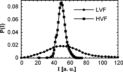
Droplet-based microfluidic techniques are useful for performing biological assays. In many such assays, it is necessary to accurately measure the reaction kinetics of enzymes encapsulated in the drops. This can be used to characterize enzymatic activity and to evolve enzymes for superior activity.7 However, to achieve an accurate measurement of catalytic activity, it is critical to incubate all drops for exactly the same time. This ensures that the reactions in the drops progress to the same extent, so that differences in product concentration are limited to differences in activity. To demonstrate that close-packed plug flow provides the control needed to measure reaction kinetics, we use it in an experiment that characterizes the activity of the enzyme β-galactosidase. The enzymes are coencapsulated with fluorogenic substrate fluorescein-di(β-D-galactopyranoside). When the enzyme hydrolyzes the substrate, fluorescein is produced, making the initially dim drops become bright. The average reaction rate can be modeled using Michaelis–Menten kinetics, from which we compute a reaction time of 10 min. Setting flow rates to form drops of the desired size, we fix the incubation tube length to achieve the needed 10 min incubation. The tube connects the outlet of the formation device to the inlet of the detection device, where the drop fluorescence is measured using a laser and a photomultiplier tube. As in previous experiments, we compare the results for low-volume fraction (Qo∕Qa=2) and high-volume fraction (Qo∕Qa=0.5) cases, maintaining the total flow rate equal at Qt=225 μL∕h. In the low-volume fraction case, we measure a broad intensity distribution with relative standard deviation of 1.1. Viewed in isolation, this might imply that the catalytic activity of the enzyme varies over a significant range. However, this is an artifact of time dispersion, revealed by the high-volume fraction data. In this case, close-packing fixes the incubation time for all drops; as a consequence, a narrow distribution is measured with relative standard deviation of 0.2; this distribution more accurately reflects the true activity of the enzyme, as shown in Fig. 3. This demonstrates that accurate measurements require controlled droplet incubation, achievable with close-packed plug flow.17
Figure 3.
Fluorescence intensity distributions of droplets containing β-galactosidase and fluorescein-di(β-D-galactopyranoside) for low-volume fraction and high-volume fraction emulsions. The broadness of the low-volume fraction emulsion is an artifact of the time dispersion due to the variation in droplet incubation time. With close-packing, time dispersion is diminished, resulting in a narrower distribution that more accurately reflects the true activity of the enzyme.
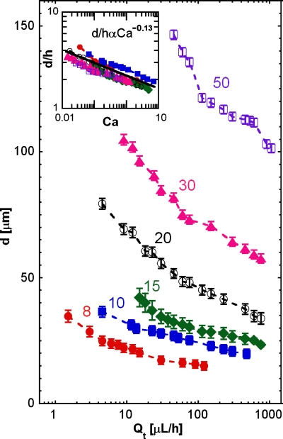
An important capability when performing reactions in drops is adjusting their size. This is usually achieved by changing the flow rate ratio of the inner and continuous phases.18 However, to exploit close-packing, the flow rate ratio between the inner and the continuous phase must be fixed above 0.64, which limits the control of drop size. Nevertheless, drop size can be varied at fixed flow rate ratio by varying drop maker nozzle dimensions; this can be achieved by fabricating drop makers of different sizes, as shown in Fig. 4, or in real time by using valve-based flow-focusing.19 Another way to adjust drop is with the total flow rate, Qt. For fixed nozzle dimensions, drop size decreases as Qt increases, as shown in Fig. 4.20 The curves for all nozzle sizes exhibit a power-law scaling, suggesting that the data can be collapsed on a master curve. We normalize the droplet diameter by the channel height and plot as a function of the capillary number Ca, inset of Fig. 4. Ca is defined as the product between the dynamic viscosity of the oil by its average velocity divided by the interfacial tension between the oil and water The data collapse on to the power law d∕hαCa−0.13, suggesting that the physics of drop formation is independent of nozzle size for the sizes investigated.21, 22
Figure 4.
Droplet diameter d as a function of absolute flow rate Qt for flow-focus drop makers with different nozzle widths, as labeled; the nozzle widths are in units of microns. d represents the diameter of a spherical drop with the same volume than the squashed droplet formed in the device. The flow rate ratio is 0.5. Inset: droplet diameter divided by nozzle height as a function of the capillary number. The data for all drop makers collapse to d∕hαCa0.13.
Close-packed plug flow allows droplet incubation to be controlled precisely and uniformly. It also allows drops to be reintroduced into devices at controlled rates, as needed when using devices in combination to perform multistep reactions and analysis. This should be useful for multistep, high-throughput applications of microfluidics, including enzyme catalysis studies,23 cell screening,24 and directed evolution.7
ACKNOWLEDGMENTS
This work supported by the NSF (DMR-1006546), the Harvard MRSEC (DMR-0820484), and the Massachusetts Life Sciences Center. The authors also thank Saint-Gobain Recherche for financial support.
References
- Joanicot M. and Ajdari A., Science 309, 887 (2005). 10.1126/science.1112615 [DOI] [PubMed] [Google Scholar]
- Anna S. L., Bontoux N., and Stone H. A., Appl. Phys. Lett. 82, 364 (2003). 10.1063/1.1537519 [DOI] [Google Scholar]
- Song H., Chen D. L., and Ismagilov R. F., Angew. Chem., Int. Ed. Engl. 45, 7336 (2006). 10.1002/anie.200601554 [DOI] [PMC free article] [PubMed] [Google Scholar]
- Schaerli Y. and Hollfelder F., Molecular Biosystems 5, 1392 (2009). 10.1039/b907578j [DOI] [PubMed] [Google Scholar]
- Tewhey R., Warner J. B., Nakano M., Libby B., Medkova M., David P. H., Kotsopoulos S. K., Samuels M. L., Hutchison J. B., Larson J. W., Topol E. J., Weiner M. P., Harismendy O., Olson J., Link D. R., and Frazer K. A., Nat. Biotechnol. 27, 1025 (2009). 10.1038/nbt.1583 [DOI] [PMC free article] [PubMed] [Google Scholar]
- Clausell-Tormos J., Lieber D., Baret J. C., El-Harrak A., Miller O. J., Frenz L., Blouwolff J., Humphry K. J., Koster S., Duan H., Holtze C., Weitz D. A., Griffiths A. D., and Merten C. A., Chem. Biol. 15, 875 (2008). 10.1016/j.chembiol.2008.08.004 [DOI] [PubMed] [Google Scholar]
- Agresti J. J., Antipov E., Abate A. R., Ahn K., Rowat A. C., Baret J. C., Marquez M., Klibanov A. M., Griffiths A. D., and Weitz D. A., Proc. Natl. Acad. Sci. U.S.A. 107, 4004 (2010). 10.1073/pnas.0910781107 [DOI] [PMC free article] [PubMed] [Google Scholar]
- Köster S., Angilè F. E., Duan H., Agresti J. J., Wintner A., Schmitz C., Rowat A. C., Merten C. A., Pisignano D., Griffiths A. D., and Weitz D. A., Lab Chip 8, 1110 (2008). 10.1039/b802941e [DOI] [PubMed] [Google Scholar]
- Li L., Mustafi D., Fu Q., Tereshko V., Chen D. L. L., Tice J. D., and Ismagilov R. F., Proc. Natl. Acad. Sci. U.S.A. 103, 19243 (2006). 10.1073/pnas.0607502103 [DOI] [PMC free article] [PubMed] [Google Scholar]
- Frenz L., Blank K., Brouzes E., and Griffiths A. D., Lab Chip 9, 1344 (2009). 10.1039/b816049j [DOI] [PMC free article] [PubMed] [Google Scholar]
- Song C., Wang P., and Makse H. A., Nature (London) 453, 629 (2008). 10.1038/nature06981 [DOI] [PubMed] [Google Scholar]
- Ajdari A., Bontoux N., and Stone H. A., Anal. Chem. 78, 387 (2006). 10.1021/ac0508651 [DOI] [PubMed] [Google Scholar]
- See supplementary material at http://dx.doi.org/10.1063/1.3576934 for a comparison of different droplet volume fractions.
- Abate A. R., Hung T., Mary P., Agresti J. J., and Weitz D. A., Proc. Natl. Acad. Sci. U.S.A. 107, 19163 (2010). 10.1073/pnas.1006888107 [DOI] [PMC free article] [PubMed] [Google Scholar]
- Baret J. C., Miller O. J., Taly V., Ryckelynck M., El-Harrak A., Frenz L., Rick C., Samuels M. L., Hutchison J. B., Agresti J. J., Link D. R., Weitz D. A., and Griffiths A. D., Lab Chip 9, 1850 (2009). 10.1039/b902504a [DOI] [PubMed] [Google Scholar]
- Mazutis L., Baret J. C., Treacy P., Skhiri Y., Araghi A. F., Ryckelynck M., Taly V., and Griffiths A. D., Lab Chip 9, 2902 (2009). 10.1039/b907753g [DOI] [PubMed] [Google Scholar]
- Sood A. K., in Solid State Physics, edited by Ehrenfest E. and Turnbull D. (Academic, New York, 1991), Vol. 45, pp. 1–73. [Google Scholar]
- Ward T., Faivre M., Abkarian M., and Stone H. A., Electrophoresis 26, 3716 (2005). 10.1002/elps.200500173 [DOI] [PubMed] [Google Scholar]
- Abate A. R., Romanowsky M. B., Agresti J. J., and Weitz D. A., Appl. Phys. Lett. 94, 023503 (2009). 10.1063/1.3067862 [DOI] [Google Scholar]
- Abate A. R., Poitzsch A., Hwang Y., Lee J., Czerwinska J., and Weitz D. A., Phys. Rev. E 80, 026310 (2009). 10.1103/PhysRevE.80.026310 [DOI] [PubMed] [Google Scholar]
- Ratulowski J. and Chang H.-C., Phys. Fluids 1, 1642 (1989). 10.1063/1.857530 [DOI] [Google Scholar]
- Ratulowski J. and Chang H.-C., J. Fluid Mech. 210, 303 (1990). 10.1017/S0022112090001306 [DOI] [Google Scholar]
- Huebner A., Olguin L. F., Bratton D., Whyte G., Huck W. T. S., de Mello A. J., Edel J. B., Abell C., and Hollfelder F., Anal. Chem. 80, 3890 (2008). 10.1021/ac800338z [DOI] [PubMed] [Google Scholar]
- Brouzes E., Medkova M., Savenelli N., Marran D., Twardowski M., Hutchison J. B., Rothberg J. M., Link D. R., Perrimon N., and Samuels M. L., Proc. Natl. Acad. Sci. U.S.A. 106, 14195 (2009). 10.1073/pnas.0903542106 [DOI] [PMC free article] [PubMed] [Google Scholar]


