Abstract
We have developed a noninvasive instrument called the bioelectric field imager (BFI) for mapping the electric field between the epidermis and the stratum corneum near wounds in both mouse and human skin. Rather than touching the skin, the BFI vibrates a small metal probe with a displacement of 180 μm in air above the skin to detect the surface potential of the epidermis through capacitative coupling. Here we describe our first application of the BFI measuring the electric field between the stratum corneum and epidermis at the margin of skin wounds in mice. We measured an electric field of 177 ± 14 (61) mV/mm immediately upon wounding and the field lines pointed away from the wound in all directions around it. Because the wound current flows immediately upon wounding, this is the first signal indicating skin damage. This electric field is generated at the outer surface of the epidermis by the outward flow of the current of injury. An equal and opposite current must flow within the multilayered epidermis to generate an intraepidermal field with the negative pole at the wound site. Because the current flowing within the multilayered epidermis is spread over a larger area, the current density and subsequent E field generated in that region is expected to be smaller than that measured by the BFI beneath the stratum corneum. The field beneath the stratum corneum typically remained in the 150–200 mV/mm range for 3 days and then began to decline over the next few days, falling to zero once wound healing was complete. The mean wound field strength decreased by 64 ± 7% following the application of the sodium channel blocker, amiloride, to the skin near the wound and increased by 82 ± 21% following the application of the Cl– channel activator, prostaglandin E2.
Electrical signals play an integral role in the function of many of our organ systems and are routinely used in the diagnosis of disease in the heart and nervous system. Our largest organ, the skin, generates a voltage across itself everywhere on the body, yet the signaling function of this “skin battery” remains largely unexplored.
This skin battery will drive an ionic current out through any wound where the resistance is low and as this “wound current” flows out of the wound it will in turn generate an electric field within the skin along the lines of current flow. Dubois–Reymond first discovered that ionic currents exit skin wounds 165 years ago using a galvanometer.1 This was confirmed by Illingworth and Barker2 using the more modern vibrating probe technique.3,4 They measured up to 10 μA/cm2 exiting accidentally amputated fingertips in children during a 2-week period following the injury. This wound current flows through the tissue which has a certain resistivity so this flow must generate an electric field in the skin bordering the wound. While this electric field has not yet been measured in humans, it has been measured in the skin of guinea pigs, newts, and salamanders (reviewed in5). The lack of human studies is due, in part, to the difficulty of carrying out recordings in human wounds using the standard microelectrode technology. We have developed a new approach, the bioelectric field imager (BFI), which does not require any electrode contact at the wound site so it makes possible the noninvasive measurement of the electric fields near mammalian wounds. Using this new tool we have revealed for the first time the electric field pattern surrounding skin wounds in mice and humans. The significance of the BFI is that it enables us to visualize the electric field lines associated with wounds noninvasively.
This electric field is the first signal generated upon wounding and it initiates the wound healing process by triggering the active migration of keratinocytes and other cell types toward the wounded region by galvanotaxis.6
The ultimate driving force for all wound currents is the voltage across the epidermis. The epidermis of the skin normally generates a voltage across itself, termed the transepidermal potential (TEP), by pumping positive ions from its apical to its basal side and Cl– from its basal to apical side. This is accomplished by segregating Na+ and Cl– channels to the apical end and K+ channels to the basal end of the epithelial cells, while utilizing a Na+/K+-ATPase to lower intracellular [Na+] and raise intracellular [K+] (Figure 1A). This low intracellular [Na+] (combined with the negative membrane potential) results in Na+ movement into the cell on the apical end where the channels are localized, and the high intracellular [K+] results in K+ efflux on the basal side where the K+ channels are localized. This transepidermal ion flux creates a TEP of between 20–50 mV, inside positive, in mammalian skin,7,8 and has been termed the “skin battery”9 (Figure 1B). After wounding, this TEP will drive current out the low resistance pathway created by the wound (Figure 1C). In intact skin, current flow is limited by the very high resistance of the stratum corneum and the tight junctions between cells that form the monolayers in the epidermis. Because this positive wound current flows toward the wound on the basal side of the epidermis, and then away from the wound on the apical side, a lateral electric field will be generated by this flow of wound current on both sides of the epidermis but will exhibit opposite polarities on the two sides (Figure 1C). This model predicts that the field just beneath the stratum corneum will be oriented with the positive pole at the wound and the negative pole away from the wound, and this field has indeed been measured in guinea pig skin to be about 100 mV/mm.7 Our preliminary measurements on human skin wounds have also detected fields of this polarity and amplitude. In contrast to this, the field deeper in the epidermal multilayer will have the opposite polarity, with the negative pole at the wound site (Figure 1C).
Figure 1.
Generation of skin wound electric fields. (A) Diagram of a typical epithelial cell in a monolayer with Na+ and Cl– channels localized on the apical plasma membrane and K+ channels localized on the basolateral membranes along with the Na+/K+-ATPase. This asymmetric distribution of ion channels generates a transcellular flow of positive current that must flow back between the cells through the paracellular pathway (Ipara). This current flow generates a transepithelial potential that is positive on the basolateral side of the monolayer. (B) Unbroken skin maintains this “skin battery” or transepidermal potential of 20–50 mV. (C) When wounded this potential drives current flow through the newly formed low resistance pathway, generating a lateral electric field whose negative vector points toward the wound center at the lower portion of the epidermis and away from the wound on the upper portion just beneath the stratum corneum (B and C reprinted with permission from Figure 2 of Current Topics in Developmental Biology (2003 58:1–26).
MATERIALS AND METHODS
The fundamental principal of this technique, originally proposed by Lord Kelvin,10 is that the unknown surface potential of an object can be determined by forming a parallel plate capacitor using a piece of metal with known potential, connecting the two surfaces and measuring the current flow between them. Zisman11 introduced an oscillating approach in which one plate is vibrated up and down to vary the capacitance and Bluh and Scott12 adapted it for measuring bioelectric potentials. By controlling the voltage on one of the plates, one can determine the value for which the capacitance becomes zero and this will only occur when there is no voltage difference between the two plates. Thus, the value of the applied voltage for which the capacitance no longer oscillates must be equal to the unknown surface potential. By applying a series of known voltages (Vb) to the probe or the skin, we can quickly determine that voltage at which there is no current flow between the two surfaces and that value is equal to the surface potential of the skin in the region next to the probe. Baikie et al.13,14 devised an approach that does not even require that the two surfaces be connected and used it to measure the electric field in a corn coleoptile. We use a similar approach here to measure the surface potential of the epidermis in both mouse and human skin.
Capacitative coupling
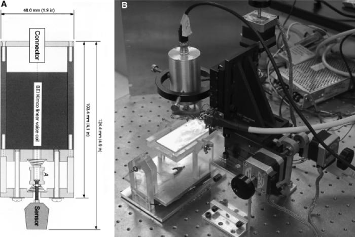
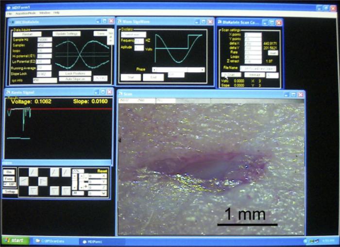
The BFI probe used in these studies was a flat copper surface 320×700 μm that was vibrated at 70 Hz while positioned with the closest approach of about 150 μm from the skin's surface with a total displacement of 180 μm and with the axis of vibration perpendicular to that surface. A voice coil is used to vibrate the probe in the vertical plane (Figure 2A) and three stepper motors move the probe in a two-dimensional grid while maintaining a constant distance between the BFI and the skin surface via feedback to the z axis stepper motor (Figure 2B). The probe is soldered directly to the negative input of either an Analog Devices 8601 (Analog Devices, Norwood, MA) or an LMC 6082M operational amplifier (National Semiconductor, Santa Clara, CA) with a 10 Megaohm feedback resistor. This assembly is potted in plastic in such a way that only the flat probe is exposed and the plastic is coated with silver paint or copper foil that is grounded to act as a shield. Because the capacitance between two flat conductors is inversely proportional to the distance between them, vibrating the BFI generates an oscillating capacitance that results in an oscillating charge movement on the probe. This is converted to an oscillating voltage and the output signal is digitized with a Data Translation 3005 board in a Pentium IV computer. Software written in Visual Basic detects the peak-to-peak value of the oscillation averaged over about 100 cycles. A computer screen shot of this program running is shown in Figure 3.
Figure 2.
Bioelectric field imager (BFI) vibrator and motorized manipulator. (A) Diagram of the vibrator using a voice coil (BEI Kimko LA 16-27-000A, Vista, CA). The vibrator assembly incorporates two springs to hold the probe in place when the voice coil is not powered. (B) Photograph of motorized manipulator used to position BFI above a wound in mouse skin. An adjustable mouse platform maintained at 37 °C is shown on the lower left and the cylinder above it is the vibrator.
Figure 3.
Photograph of computer screen during a typical scan of a wound. Upper left panel displays real-time voltage signal from the probe and allows the user to select amount of averaging and range of Vb. Upper middle panel allows user to select frequency of vibration and phase of signal analysis. Upper right panel allows user to specify the x–y distribution of the potential measurements to be made, number of loops to be averaged and the file name for data storage. The voltage is plotted in real time in the middle left panel and probe position can be controlled in the lower left panel. Lower right panel displays an image of the wound that is being scanned that was photographed through a stereoscope before scanning.
Determining the surface potential
Because the oscillating charge is proportional to the voltage difference between the probe and the skin, one can determine the skin's unknown surface potential by placing several different voltage values (Vb) on the probe or the skin and determining that value for which the charge oscillations go to zero. That voltage must be equal to the unknown surface potential but of opposite polarity. Rather than stepping through many different voltage values to find the zero point, we measure the peak-to-peak voltage oscillation when ± 10 V is applied to the skin and draw a line between these values plotting Vptp on the ordinate and Vb on the abscissa. Where this line crosses the abscissa, Vptp equals 0 and the Vb value there is equal to the surface potential as described previously.14 The slope of this line is inversely proportional to the distance between the probe and the skin and we use that information to maintain a constant distance between the two surfaces by feedback to the z-axis stepper motor.
Artifacts uncovered and eliminated
Our first series of measurements indicated electric fields that were an order of magnitude larger than the ones shown here. We had shaved the hair off of those mice but found it very difficult to remove all hair from a given region by shaving alone. We quickly learned that the BFI is very sensitive to the static electrical charge on hair. Once the hair was more completely eliminated by applying a 50% solution of the hair removal product, Nair, or by using hairless mice, this problem was eliminated. The second artifact that we discovered was due to the difference in work function (affinity for electrons) between the skin and interstitial fluid. Because the center of a wound is often filled with fluid, we observed a large signal that was due mainly to the work function difference rather than the electric field generated by the wound current. We found that this could be eliminated by placing a thin layer of polyvinyl film over the wound before scanning. The film surface has a uniform work function and renders invisible the work function of the surface beneath it while being transparent to the electric field beneath it. All of the measurements included in this report were made with this film on the object being scanned except the hand wound imaged in Figure 7, which had no fluid at the wound site.
Figure 7.
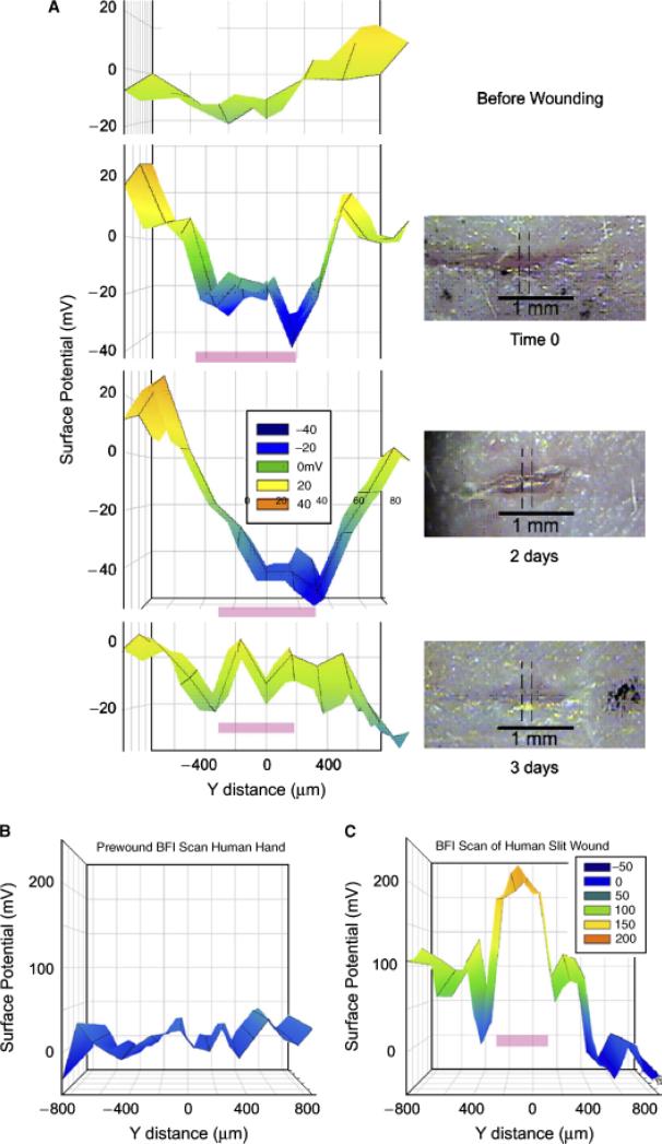
Bioelectric field imager (BFI) scans of skin wounds over time. (A) Mouse skin wound scanned before and at the indicated times after wounding. The precise region that was scanned is indicated by the dotted lines on the micrographs. Pink bar on the BFI scan indicates the location of the wound. (B) BFI scan of human skin before wounding it. (C) BFI scan just after wounding back of hand with a full-thickness incision. Pink bar indicates location of wound on the scan.
Animals
Mice ranged in age between 3 weeks and 6 months and both CF-1 and SKH-1 strains were used. Wounding and measurements were done under complete inhalation anesthesia using 1.4% isoflurane in O2. Wounds of various sizes and shapes were inflicted on the backs of the mice with either a scalpel or iridectomy scissors and scanned periodically until healing was complete within 3–8 days. All animal procedures were approved by the institutional animal care and use committees at either the Marine Biological Laboratories or the University of Connecticut Health Center or Eastern Virginia Medical School.
Informed consent was obtained from the human subject used in this study, and the study protocol conformed to the ethical guidelines of the 1975 Declaration of Helsinki. The use of this noninvasive technique to measure the electric field near human skin wounds was approved by the Eastern Virginia Medical School Institutional Review Board.
RESULTS
Demonstrating that the BFI reliably measures surface potentials
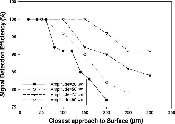
We conducted some tests of the BFI to determine that it was performing properly. The first was a study of the dependence of the signal on vibration amplitude and distance from the surface. We held a metal plate at a fixed voltage and measured the BFI signal at fixed distances from the plate for four different vibration amplitudes (Figure 4).
Figure 4.
Signal detection efficiency of a 0.2 mm2 sensor vibrating at 70 Hz falls off with distance from the surface and is also dependent on vibration amplitude (defined as half of the total excursion distance of the probe tip).
From these data it is clear that when vibrating at 70 Hz, a vibration amplitude of 90 mm is needed in order to detect 100% of the surface potential with a 150 μm distance between the surface and the closest approach of the sensor. Consequently we adopted this amplitude for all of the wound field measurements included in this paper. When using the BFI one must keep this distance limitation in mind. The distance between the closest approach of the sensor and the epidermal surface is the critical parameter. Nonconductive dielectrics such as the stratum corneum or polyvinyl film that separate the epidermis from the sensor must be < 150 μm thick for optimal signal detection.
This is normally not a problem because polyvinyl films such as Saran Wrap are about 10 μm thick and both human and murine stratum corneum are < 20 μm thick in most skin regions.15
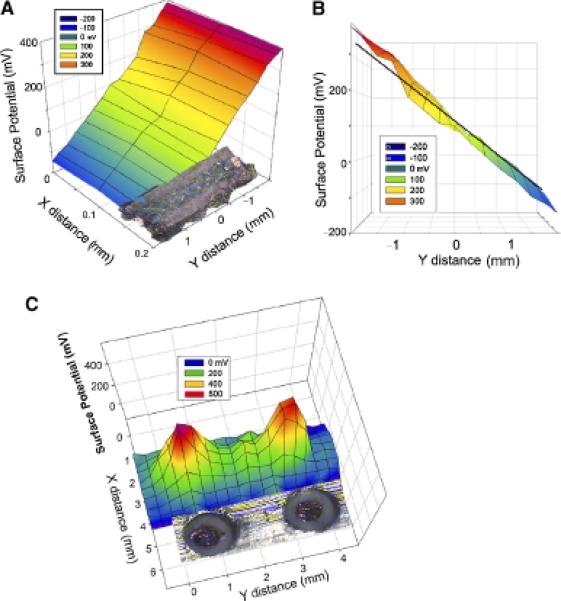
We chose two well-defined surface potential configurations to test the BFI. The first was a linear voltage gradient generated by passing current through a carbon resistor with one side milled flat (Figure 5A and B). We observed the expected linear voltage gradient along this resistor. The second configuration was composed of two copper disks held at 500 mV. We scanned these in a two-dimensional grid pattern and generated the surface potential distribution shown in Figure 5C. This distribution matched the voltage profile expected when using a sensor that is 350 μm × 700 μm and did not change when a layer of polyvinyl film was placed over the disks to mimic the stratum corneum.
Figure 5.
Surface potential of resistor with a 109 mV/mm field within it. (A) Two-dimensional scan of the resistor indicates the expected uniform field of 109 mV/mm. (B) Side view of same data with superimposed black line indicating the expected potential gradient within the resistor. (C) Bioelectric field imager (BFI) scan of two copper disks held at 500 mV. Disks were 0.8 mm in diameter and a photograph of them is aligned with the BFI scan.
Imaging the electric field near wounds in mouse skin
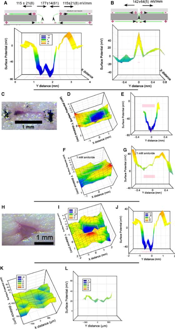
We began our studies using CF-1 female mice that have a normal hair density. We removed the hair on a 1 sq. in. region of the back by first cutting the hair with scissors followed by applying a 50% Nair solution for 2 minutes. Complete hair removal was important because we found that the static charge on hair could influence surface potential readings. This treatment not only removes hair but stops further hair growth for several days. Midway through this study we switched to the hairless mouse strain, SHK-1 and stopped using Nair. However, we obtained similar readings from wounds studied in both of these mouse strains. Before wounding, a BFI scan of the skin generallyreveals afairlyuniform surface potential with a maximum variation of about 60 mV over the entire scan (Figure 6K and L). Immediately following wounding, an electric field can be detected in the skin around the wound (Figure 6A–J) and the field pattern depends on the width of the wound. For wounds in which the epidermis separates, exposing the current flowing out from beneath the epidermis, the region over the wound is usually negative with respect to the surrounding skin by 177 ± 14(61) mV/mm (mean ± SEM[N]) (Figure 6A). This electric field value is determined by dividing the surface potential difference between two positions by the distance between them. In addition to the clearly negative region directly over the wound, a surface potential gradient of 115 ± 64 mV/mm is usually found in a region that is approximately 1 mm wide measured from the edge of the wound outward. This is generated by the current flowing in the narrow space between the stratum corneum and the stratum granulosum. The field in this region has been measured previously in guinea pigs using contact electrodes that penetrated the stratum corneum and a similar polarity and field strength were reported.7 For wounds in which there is not much separation of the epidermis, the negative region is not present because the lower wound region where current flows out is not exposed and the BFI only detects the current flowing away from the wound beneath the stratum corneum as illustrated in Figure 6B. This electric field pattern is distinctly different from that shown in Figure 6A.
Figure 6.
Summary of results observed on mouse skin wounds. Pink bars mark the wound location on the scan. (A) Common field profile for wounds with a significant break in the epidermis. (B) Common field profile for a wound with very little separation of the epidermis. (C) Photomicrograph of linear wound scanned in (D–G). (D) Two-dimensional scan of voltage profile over wound. (E) Cross section of “D” along the y axis at x=0. (F,G). Bioelectric field imager (BFI) scans made after the application of 1 mM amiloride to the wound. (H) Photomicrograph of a larger, nonlinear wound. (I) Two-dimensional BFI scan of wound in H. (J) Cross section of “I” along y axis at x=0. (K, L): Control scans of a 3mm2 region of unwounded mouse skin with a layer of polyvinyl film (Saran wrap) adhering closely to it K. Two-dimensional profile of surface potential indicates all regions fall within a range of 60 mV. L. Cross section view of a 200 μm wide strip from K along the y axis at x=0.
Wound field can be modified pharmacologically
We applied two different drugs to test for the involvement of specific ions in the generation of the wound field. The application of the sodium channel blocker, amiloride (1 mM dissolved in phosphate-buffered saline) reduced the wound field by 68% on average (Figure 6F and G, Table 1). In contrast, application of the Cl– channel activator, prostaglandin E2, enhanced the electric field by 82% on average (Table 1). This suggests that both Na+ influx and Cl– efflux are carrying the wound current.
Table 1.
Changes in wound field in response to ion channel affecters
| No. mice studied | No. of wounds | Mean % change ± SEM (N) | |
|---|---|---|---|
| PBS Control3 increase | 2 | 3 | 22 ± 203 increase |
| Amiloride in PBS | 9 | 11 | 64 ± 711 decrease |
| Prostaglandin E2 in PBS | 4 | 7 | 82 ± 217 increase |
PBS, phosphate-buffered saline.
Time course of the wound field
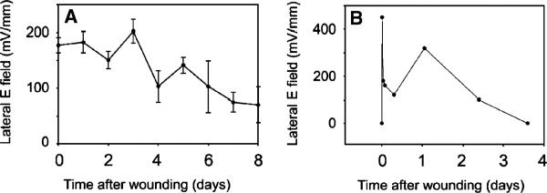
The field persists in these mouse wounds until the wound appears healed (Figures 7 and 8A). For the small (1–3 mm long) wounds that we studied this typically occurred in 3–8 days.
Figure 8.
Time course of wound field. (A) Mean electric field at the edge of a wound in mouse skin as a function of time after wounding. Each data point is an average of 7–18 different wound field measurements. Bars represent scanning electron microscopy. (B) Time course of electric field amplitude near a wound on the back of a human hand as it heals over 3 days.
Measurements near wounds in human skin
The BFI scanning system requires that the subject remain very still during the scan of the wound. The duration of the scan depends on the number of positions sampled so we used a narrow scan of three positions along the “x” axis and 18 along the “y” axis for a total number of 54 measurements requiring a scan time of 14 minutes. We found that we could immobilize human fingers or hands for this period of time using a metal splint or clamp. We made a 1.5 mm-long linear incision through both the epidermis and the dermis of the upper hand with iridectomy scissors and explored the field along a narrow strip perpendicular to the axis of the wound with the BFI (Figure 7B and C). We observed an electric field near the wound that was very similar to that found in mouse skin. The field was present for 3 days at which time the wound appeared healed (Figure 8B). Further human studies will require shorter data acquisition times and a more portable detector that does not require immobilization of the skin region being studied.
DISCUSSION
Origin and role of the endogenous wound current and electric field
The endogenous electric field generated near skin wounds is of interest because keratinocyte migration and wound healing are strongly influenced by such fields.5,16 The directional migration of cells in an electric field (galvanotaxis) is quite common. Among the cell types found to exhibit this response are amoebae, slime molds, paramecia, macrophages, leukocytes, granulocytes, chondrocytes, osteoblasts, osteoclasts, fibroblasts, epithelial cells, neural crest cells, and cancer cells.16,17 The migration of human skin-derived keratinocytes is also guided by electric fields, notably of the same magnitude as those found in mammalian wounds.6,18–24 This naturally leads to the question of whether imposing an external electric field might stimulate wound healing. Dozens of reviews of studies using electric stimulation of chronic wounds in humans have appeared and most indicate that electric field application has a beneficial effect on wound healing.25 However, the best controlled studies have been carried out on other animals. Chiang et al.26 have provided compelling evidence for a role of endogenous electric fields in wound healing in the newt. When wound electric fields are nullified either pharmacologically or electrically, the rate of wound reepithelialization is significantly reduced. McCaig and Zhao have thoroughly investigated wound healing in a mammalian system, the rat cornea.27–30 They find that the rate of corneal wound healing is greater at higher imposed field strengths. Pharmacologically enhancing or decreasing wound-induced ionic currents has been shown to increase or decrease wound healing rates, respectively, in rat cornea.31 These well-controlled studies support an important role for endogenous electric fields in the wound healing process.
Comparison of the BFI technique with other published methods for measuring electric signals at skin wounds
There are two distinct components that comprise the skin wound's electric signal: (1) the current of injury that is driven out of the wound by the TEP; and (2) the lateral electric field generated by this current as it flows through the skin tissue. The former was first detected with a galvanometer1 and more recently with the self-referencing vibrating probe technique.2,3 That probe oscillates a spherical platinum-black electrode about 30 μm in diameter in a fluid medium and detects the voltage gradient between the two extremes of its vibration that is generated by the flow of current through the medium. If human skin is immersed in a liquid medium, an injury current on the order of 10 μA/cm2 can be detected flowing out of the wound2,4 and this current decreases over time as the wound heals. However, the electric signal that is more relevant to wound healing is the electric field generated within the epidermis where the keratinocytes reside. They migrate towards the wound to initiate wound closure and their migration direction is influenced by electric fields as low as 10 mV/mm. Moreover, wound angiogenesis may also be guided by the electric field at the wound.32 The endogenous lateral electric field points toward the wound from all directions around it and is the first signal initiating the wound healing process. One can use the current density exiting the wound to estimate tissue fields by assuming an average tissue resistivity, but that does not provide spatial information about the electric field. Obtaining such spatial information requires a more direct measurement of the electric field itself.
The conventional method to detect such lateral electric fields near skin wounds would be to insert electrode pairs into the epidermis and measure the voltage difference between regions lateral to the wound site. Reported measurements of electric fields in wounds in animals used either glass microelectrodes or micropuncture silver wire electrodes.7 Both the depth and relative lateral spacing of electrode tip placement is difficult to reliably reproduce because the electrodes must be positioned using a micro-manipulator that is mounted on a support that is usually not directly attached to the subject under study. Therefore, any slight movement by the subject can exert a stress on the electrode, which does not move with the subject. In addition these dc electrode instruments must be placed in an electromagnetically shielded cage to reduce pickup of electric signals from the environment. This hampers the portability and ultimate patient utility of this measurement system.
The BFI's capacitative coupling approach avoids both of these problems. The probe vibrates in air above the skin eliminating the need for direct contact and our detector only amplifies signals coming in at the vibration frequency, eliminating the need for electromagnetic shielding. However, one limitation of the BFI approach is that we can only detect the electric field on the nearest conductive surface. That allows the BFI to detect the field between the epidermis and the stratum corneum in skin but it cannot measure fields within the epidermis or deeper in the body.
What is the electric field within the multilayered epidermis?
Because the BFI only detects the electric field at the outer surface of the epidermis, we can only estimate the magnitude of the field deeper in the epidermis where the keratinocytes reside. One approach at this estimation is to consider the current path taken by the wound current (Figure 1C). The current flowing away from the wound on the outer surface of the epidermis must flow through the rather tight space beneath the stratum corneum. The smaller the space through which current flows, the higher the current density and the electric field is directly proportional to this current density. In contrast, the return current can flow between any of the four layers of cells comprising the murine epidermis33 so that the area through which the current is flowing is perhaps four times greater, lowering the current density by that factor. Because the electric field is equal to the current density multiplied by the resistivity of the path traversed by the current, one would expect the field within the epidermis to be about one-fourth as large as that measured by the BFI. While the total current flowing away from the wound, beneath the stratum corneum, must equal the total flowing toward the wound within the epidermis, the current densities in the two regions will be quite unequal, making the electric field in this latter region lower than that beneath the stratum corneum. This reasoning would predict a value of about 40 mV/mm within the epidermis with the negative pole of the field at the wound site.
Insights into the mechanisms used by cells to detect electric fields
The ability of human keratinocytes to detect physiological electric fields depends on the involvement of several molecules and signaling pathways. Ca2+ influx was among the first requirements identified,34 followed by protein kinases, PKA, ERK, and PI3K20,23,29,35 and growth factor receptors.19,23,36–38 When keratinocytes are placed in a physiological electric field in vitro, EGF receptors become more concentrated on the side of the cell facing the cathode within 5 minutes.19 This has also been observed in corneal epithelial cells39 but the response seems too rapid to be a result of lateral electrophoresis of membrane-bound receptors.40 This asymmetry in the distribution of EGF receptors may be important for the directed migration response, but no single “sensor” for this galvanotaxis response has been identified as yet.
Recent work from Zhao's group has identified the first gene involved in this signal transduction.29 They genetically disrupted the γ subunit of phosphatidylinositol-3-kinase, p110γ, and observed an impaired electrotaxis response of keratinocytes. This kinase increases the concentration of PIP3 in the plasma membrane. In addition, the tissue-specific deletion of the gene, phosphatase and tensin homolog (Pten), enhanced the electrotaxis response. This phosphatase normally reduces PIP3 levels. This work identified the first genes that modulate electrotaxis and suggests that the membrane concentration of PIP3 is important for the signal transduction in electrotaxis.
In conclusion, the BFI is a noninvasive method to detect electric fields at the surface of the mammalian epidermis. This first application of this method describes the existence of an electric field in the range of 115–180 mV/mm at the edge of skin wounds in mice and man. This field is continually present until wound closure is complete.
ACKNOWLEDGMENTS
This work was supported by NIH:NCRR P41RR01395 to P.J.S. Smith and NIH R44 GM069194 to R. Nuccitelli. We thank the expert reviewers and editors for comments and suggestions that improved this manuscript.
Glossary
- μm
Microns
- BFI
Bioelectric Field Imager
- PBS
Phosphate-buffered saline
- PIP3
Phosphatidyl-inositol 3,4,5 trisphosphate
- Pten
Phosphatase and tensin homolog
- TEP
Transepidermal potential
- Vptp
Peak-to-peak voltage
REFERENCES
- 1.DuBois-Reymond E. Vorlaufiger abrifs einer untersuchung uber den sogenannten froschstrom und die electomotorischen fische. Ann Phys U Chem. 1843;58:1. [Google Scholar]
- 2.Illingworth CM, Barker AT. Measurement of electrical currents emerging during the regeneration of amputated fingertips in children. Clin Phys Physiol Meas. 1980;1:87–9. [Google Scholar]
- 3.Jaffe LF, Nuccitelli R. An ultrasensitive vibrating probe for measuring extracellular currents. J Cell Biol. 1974;63:614–28. doi: 10.1083/jcb.63.2.614. [DOI] [PMC free article] [PubMed] [Google Scholar]
- 4.Reid B, Nuccitelli R, Zhao M. Non-invasive measurement of bioelectric currents with a vibrating probe. Nat Protoc. 2007;2:661–9. doi: 10.1038/nprot.2007.91. [DOI] [PubMed] [Google Scholar]
- 5.Nuccitelli R. A role for endogenous electric fields in wound healing. Curr Top Dev Biol. 2003;58:1–26. doi: 10.1016/s0070-2153(03)58001-2. [DOI] [PubMed] [Google Scholar]
- 6.Nishimura KY, Isseroff RR, Nuccitelli R. Human keratinocytes migrate to the negative pole in direct current electric fields comparable to those measured in mammalian wounds. J Cell Sci. 1996;109:199–207. doi: 10.1242/jcs.109.1.199. [DOI] [PubMed] [Google Scholar]
- 7.Barker AT, Jaffe LF, Vanable JW., Jr The glabrous epidermis of cavies contains a powerful battery. Am J Physiol. 1982;242:R358–66. doi: 10.1152/ajpregu.1982.242.3.R358. [DOI] [PubMed] [Google Scholar]
- 8.Foulds IS, Barker AT. Human skin battery potentials and their possible role in wound healing. Br J Dermatol. 1983;109:515–22. doi: 10.1111/j.1365-2133.1983.tb07673.x. [DOI] [PubMed] [Google Scholar]
- 9.McGinnis ME, Vanable JW., Jr Electrical fields in Notophthalmus viridescens limb stumps. Dev Biol. 1986;116:184–93. [Google Scholar]
- 10.Kelvin L. Contact electricity of metals. Philosophical Mag. 1898;46:82–120. [Google Scholar]
- 11.Zisman WA. A new method of measuring contact potential differences in metals. Rev Sci Instr. 1932;3:367–70. [Google Scholar]
- 12.Bluh O, Scott BIH. Vibrating probe electrometer for the measurement of bioelectric potentials. Rev Sci Instr. 1950;21:867–8. doi: 10.1063/1.1745444. [DOI] [PubMed] [Google Scholar]
- 13.Baikie ID, Estrup PJ. Low cost PC based scanning Kelvin probe. Rev Sci Instr. 1998;69:3902–7. [Google Scholar]
- 14.Baikie ID, Smith PJS, Porterfield DM, Estrup PJ. Multitip scanning bio-Kelvin probe. Rev Sci Instr. 1999;70:1842–50. [Google Scholar]
- 15.Egawa M, Hirao T, Takahashi M. In vivo estimation of stratum corneum thickness from water concentration profiles obtained with Raman spectroscopy. Acta Derm Venereol. 2007;87:4–8. doi: 10.2340/00015555-0183. [DOI] [PubMed] [Google Scholar]
- 16.McCaig CD, Rajnicek AM, Song B, Zhao M. Controlling cell behavior electrically: current views and future potential. Physiol Rev. 2005;85:943–78. doi: 10.1152/physrev.00020.2004. [DOI] [PubMed] [Google Scholar]
- 17.Nuccitelli R. Physiological electric fields can influence cell motility, growth, and polarity. Adv Cell Biol. 1988;2:213–33. [Google Scholar]
- 18.Sheridan DM, Isseroff RR, Nuccitelli R. Imposition of a physiologic DC electric field alters the migratory response of human keratinocytes on extracellular matrix molecules. J Invest Dermatol. 1996;106:642–6. doi: 10.1111/1523-1747.ep12345456. [DOI] [PubMed] [Google Scholar]
- 19.Fang KS, Ionides E, Oster G, Nuccitelli R, Isseroff RR. Epidermal growth factor receptor relocalization and kinase activity are necessary for directional migration of keratinocytes in DC electric fields. J Cell Sci. 1999;112(Part 12):1967–78. doi: 10.1242/jcs.112.12.1967. [DOI] [PubMed] [Google Scholar]
- 20.Pullar CE, Isseroff RR, Nuccitelli R. Cyclic AMP-dependent protein kinase A plays a role in the directed migration of human keratinocytes in a DC electric field. Cell Motil Cytoskeleton. 2001;50:207–17. doi: 10.1002/cm.10009. [DOI] [PubMed] [Google Scholar]
- 21.Gruler H, Nuccitelli R. The galvanotaxis response mechanism of keratinocytes can be modeled as a proportional controller. Cell Biochem Biophys. 2000;33:33–51. doi: 10.1385/CBB:33:1:33. [DOI] [PubMed] [Google Scholar]
- 22.Pullar CE, Isseroff RR. Cyclic AMP mediates keratinocyte directional migration in an electric field. J Cell Sci. 2005;118(Part 9):2023–34. doi: 10.1242/jcs.02330. [DOI] [PubMed] [Google Scholar]
- 23.Pullar CE, Baier BS, Kariya Y, Russell AJ, Horst BA, Marinkovich MP, Isseroff RR. beta4 integrin and epidermal growth factor coordinately regulate electric field mediated directional migration via Rac1. Mol Biol Cell. 2006;17:4925–35. doi: 10.1091/mbc.E06-05-0433. [DOI] [PMC free article] [PubMed] [Google Scholar]
- 24.Pullar CE, Zhao M, Song B, Pu J, Reid B, Ghoghawala S, McCaig C, Isseroff RR. Beta-adrenergic receptor agonists delay while antagonists accelerate epithelial wound healing: evidence of an endogenous adrenergic network within the corneal epithelium. J Cell Physiol. 2007;211:261–72. doi: 10.1002/jcp.20934. [DOI] [PubMed] [Google Scholar]
- 25.Kloth LC. Electrical stimulation for wound healing: a review of evidence from in vitro studies, animal experiments, and clinical trials. Int J Low Extrem Wounds. 2005;4:23–44. doi: 10.1177/1534734605275733. [DOI] [PubMed] [Google Scholar]
- 26.Chiang M, Cragoe EJ, Jr., Vanable JW., Jr Intrinsic electric fields promote epithelialization of wounds in the newt, Notophthalmus viridescens. Dev Biol. 1991;146:377–85. doi: 10.1016/0012-1606(91)90239-y. [DOI] [PubMed] [Google Scholar]
- 27.Sta Iglesia DD, Vanable JW., Jr Endogenous lateral electric fields around bovine corneal lesions are necessary for and can enhance normal rates of wound healing. Wound Repair Regen. 1998;6:531–42. doi: 10.1046/j.1524-475x.1998.60606.x. [DOI] [PubMed] [Google Scholar]
- 28.Song B, Zhao M, Forrester JV, McCaig CD. Electrical cues regulate the orientation and frequency of cell division and the rate of wound healing in vivo. Proc Natl Acad Sci USA. 2002;99:13577–82. doi: 10.1073/pnas.202235299. [DOI] [PMC free article] [PubMed] [Google Scholar]
- 29.Zhao M, Song B, Pu J, Wada T, Reid B, Tai G, Wang F, Guo A, Walczysko P, Gu Y, Sasaki T, Suzuki A, Forrester JV, Bourne HR, Devreotes PN, McCaig CD, Penninger JM. Electrical signals control wound healing through phosphatidylinositol-3-OH kinase-gamma and PTEN. Nature. 2006;442:457–60. doi: 10.1038/nature04925. [DOI] [PubMed] [Google Scholar]
- 30.Song B, Gu Y, Pu J, Reid B, Zhao Z, Zhao M. Application of direct current electric fields to cells and tissues in vitro and modulation of wound electric field in vivo. Nat Protoc. 2007;2:1479–89. doi: 10.1038/nprot.2007.205. [DOI] [PubMed] [Google Scholar]
- 31.Reid B, Song B, McCaig CD, Zhao M. Wound healing in rat cornea: the role of electric currents. FASEB J. 2005;19:379–86. doi: 10.1096/fj.04-2325com. [DOI] [PMC free article] [PubMed] [Google Scholar]
- 32.Bai H, McCaig CD, Forrester JV, Zhao M. DC electric fields induce distinct preangiogenic responses in microvascular and macrovascular cells. Arterioscler Thromb Vasc Biol. 2004;24:1234–9. doi: 10.1161/01.ATV.0000131265.76828.8a. [DOI] [PubMed] [Google Scholar]
- 33.Allen TD, Potten CS. Ultrastructural site variations in mouse epidermal organization. J Cell Sci. 1976;21:341–59. doi: 10.1242/jcs.21.2.341. [DOI] [PubMed] [Google Scholar]
- 34.Trollinger DR, Isseroff RR, Nuccitelli R. Calcium channel blockers inhibit galvanotaxis in human keratinocytes. J Cell Physiol. 2002;193:1–9. doi: 10.1002/jcp.10144. [DOI] [PubMed] [Google Scholar]
- 35.Nuccitelli R, Smart T, Ferguson J. Protein kinases are required for embryonic neural crest cell galvanotaxis. Cell Motil Cytoskeleton. 1993;24:54–66. doi: 10.1002/cm.970240107. [DOI] [PubMed] [Google Scholar]
- 36.Zhao M, Agius-Fernandez A, Forrester JV, McCaig CD. Orientation and directed migration of cultured corneal epithelial cells in small electric fields are serum dependent. J Cell Sci. 1996;109:1405–14. doi: 10.1242/jcs.109.6.1405. [DOI] [PubMed] [Google Scholar]
- 37.Fang KS, Farboud B, Nuccitelli R, Isseroff RR. Migration of human keratinocytes in electric fields requires growth factors and extracellular calcium. J Invest Dermatol. 1998;111:751–6. doi: 10.1046/j.1523-1747.1998.00366.x. [DOI] [PubMed] [Google Scholar]
- 38.Pu J, McCaig CD, Cao L, Zhao Z, Segall JE, Zhao M. EGF receptor signalling is essential for electric-field-directed migration of breast cancer cells. J Cell Sci. 2007;120(Part 19):3395–403. doi: 10.1242/jcs.002774. [DOI] [PubMed] [Google Scholar]
- 39.Zhao M, Pu J, Forrester JV, McCaig CD. Membrane lipids, EGF receptors, and intracellular signals colocalize and are polarized in epithelial cells moving directionally in a physiological electric field. FASEB J. 2002;16:857–9. doi: 10.1096/fj.01-0811fje. [DOI] [PubMed] [Google Scholar]
- 40.Jaffe LF. Electrophoresis along cell membranes. Nature (London) 1977;265:600–2. doi: 10.1038/265600a0. [DOI] [PubMed] [Google Scholar]


