Abstract
Fractographic analysis of clinically failed dental ceramics can provide insights as to the failure origin and related mechanisms. One anterior 6-unit all-ceramic zirconia fixed partial denture (FPD) (Cercon®) has been clinically recovered and examined using qualitative fractography. The purpose was to identify the fracture origin and to state the reasons for failure. The recovered parts of the zirconia FPD were microscopically examined to identify classic fractographic patterns such as arrest lines, hackle, twist hackle and wake hackle. The direction of crack propagation was mapped and interpreted back to the origin of failure at the interface of the occlusalpalatal tip of the core and the veneering ceramic. An inappropriate core drop design favoring localized stress concentration combined with a pore cluster in the veneering ceramic at the core tip interface were the reasons for this premature through-the-core thickness failure.
Keywords: Fractography, failure analysis, ceramic restoration, zirconia, fixed partial denture, dental ceramic
1. Introduction
An increasing number of all-ceramic materials are being used in prosthetic dentistry. All-ceramic prostheses, the so-called fixed partial dentures (FPDs) in most cases consist of a supporting, high strength zirconia framework structure and an esthetic veneering ceramic (Raigrodski, 2004).
Clinical studies in an academic environment using zirconia supported FPDs reported promising results for an observation time of two to five years (Raigrodski et al., 2006; Tinschert et al., 2008; Sailer et al., 2007; Vult van Steyern et al., 2005; Molin and Karlsson, 2008; Beuer et al., 2009). The zirconia frameworks showed excellent mechanical stability as only one fracture occurred in each of two studies on FPDs (Sailer et al., 2007; Beuer et al., 2009). However, several authors reported up to 15% of the frameworks had minor chipping of the veneering ceramic (Raigrodski et al., 2006; Tinschert et al., 2008; Sailer et al., 2007; Vult van Steyern et al., 2005). Nevertheless, when using anatomically designed frameworks, Molin et al. observed no veneer chipping after five years of observation time. A five year follow-up in three dental private practices (Kerschbaum et al., 2009), regrouping 259 bridges and 957 crowns (Cercon® system), reported 8 % veneer and framework fractures. The authors suspected the early framework fractures in the connector area were caused by an inadequate connector cross-section and subsequent grinding without water cooling of the zirconia frameworks as well as a learning curve of the laboratories working with CAD-CAM technology. Connector areas are at increased risk of failure if the radius of curvature is reduced (Plengsombut et al., 2009; Oh and Annusavice, 2002). The gingival embrasures of connectors are shown to be the site of highest stress concentration when using finite element (FE) modeling (Dittmer et al., 2009). Insufficient connector dimensions, framework grinding damage while making shape adjustments, positioning of the connector outside the arch of occlusion, all contribute to connector failures (Aboushelib et al., 2009). In the anterior sector, connector dimensions may be difficult to achieve and dental technicians tend to create sharp embrasure forms to improve the esthetics (Oh and Annusavice, 2002).
Fractography is a well established tool in engineering to examine fractured, brittle surfaces (Frechette, 1990; Mecholsky, 1995; Quinn, 2007). The use of fractographic pattern and surface feature recognition has been applied in dentistry to clinical ceramic restoration failure analyses (Thompson et al., 1994; Quinn et al., 2005; Scherrer et al., 2006; Scherrer et al., 2007; Scherrer et al., 2008; Taskonak et al., 2008). Features like compression curl, hackle, wake hackle, twist hackle, and arrest lines were the most commonly found markings in failed all-ceramic restorations. (Quinn et al., 2005; Scherrer et al., 2006; Scherrer et al., 2007; Scherrer et al., 2008). Those markings are all contribute to identify the direction of crack propagation (dcp) and failure origin to finally state the specific reasons for failure.
The purpose of this work was to fractographically analyze the broken parts of an in vivo fractured six unit anterior zirconia FPD, revealing the responsible causes for premature failure.
2. Materials and Methods
A 24 hours in vivo fractured anterior (canine to canine) six-unit maxillary FPD was provided by a dental clinician, as shown in Fig 1. The FPD was manufactured by that dental technician in a private laboratory who had been trained in CAD/CAM techniques and handling the Cercon® system (Cercon® base, Degudent, Hanau, Germany)* for the zirconia framework. The Cercon® framework consisted of a Y-TZP sintered at 1350°C, (coefficient of thermal expansion (CTE): αf = 10.5 × 10⁻⁶ 1/K) and veneered with a feldspar-based porcelain (αv = 9.9 × 10⁻⁶ 1/K) (Elephant® Sakura, Elephant Dental, Hoorn, Netherlands). For FPDs, connector dimensions of 9 mm2 are recommended by the Cercon manufacturer. According to the dental technician, after CAD-CAM machining, the framework was manually adjusted by reshaping the palatal surface. A final regeneration firing was conducted at 1000°C for 15 min, even though not necessarily recommended by the manufacturer. According to the clinician, additional occlusal grinding adjustments were performed as a fine-tuning step after veneering prior to luting the bridge with a temporary cement (Temp Bond®, Kerr Hawe, Bioggio, Switzerland) on the three abutment teeth, two canines and the central right incisor ( #13, #11, #23 FDI numbering system), for an initially planed one week try-out period. A through-the-core fracture occurred while chewing after 24 hours in vivo at the connector level between the abutment teeth #11 (central incisor) and the lateral incisor pontic #12. The patient reported no excessive or abnormal loading events during the day.
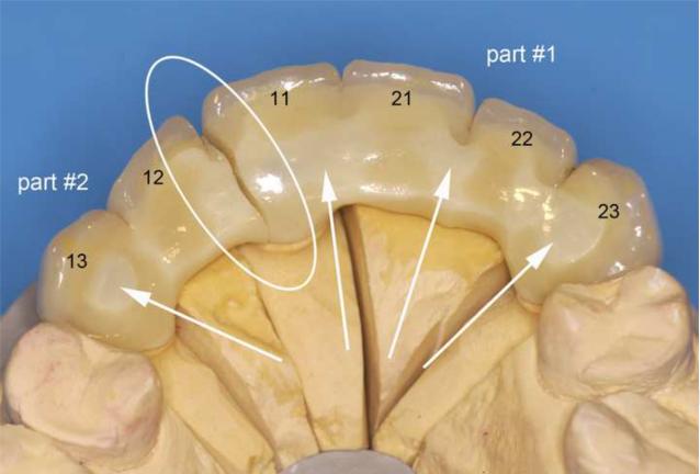
Figure 1.
Cercon® veneered six-unit anterior zirconia bridge, fractured between the upper teeth 11 and 12 in the maxillary arch (FDI numbers for each relevant tooth are labelled). The fracture surface distal of tooth #11 is labelled part #1, the fracture surface mesial of tooth #12 is labelled part #2. The region of fracture and exposed zirconia core structure are indicated by the arrows and the loading direction is indicated in red.
The fractographic examination of the two retrieved fragments was performed using a systematic approach (Scherrer et al., 2008) with light stereomicroscopy (LM) as well as scanning electron microscopy (SEM). Prior to the microscopic investigation, the broken pieces were cleaned in an ultrasonic alcohol bath for 10 min. The macroscopic appearance was examined using the LM (SV11, Zeiss, Oberkochen, Germany) under different illumination. The SEM (Leitz ISI SR 50, Akashi, Japan) was used for characterization of morphology, microstructure and fractographic details on the fractured surfaces.
3. Results
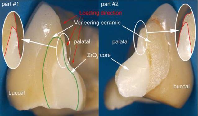
Figure 1 shows the global palatal overview of the Cercon® six-unit anterior zirconia bridge repositioned on the working stone model. The fracture is located at the connector level (white circle) between the central right incisor (tooth #11) and the pontic tooth #12. The two fractured parts analyzed have been labeled part #1 for the fractured surface view towards tooth #11 and part #2 for the fractured surface view towards tooth #12. From the palatal direction, regions of exposed zirconia core structure can be seen as indicated by the arrows. The actual fracture planes of the fractured parts #1 and #2 are shown in Fig 2. The zirconia core has a non-suitable drop-shape connector design (outlined in red), whereas the veneering porcelain shows a high volume on the buccal side but is almost absent from the occlusalpalatal surface. The green line indicates what would have been a more clinically appropriate shape and positioning of the framework connector. Fig. 3 provides a SEM close-up view of part # 2. On this image, the actual connector area was measured to be only 8.4 mm2 using image analysis software (KL ACI Focus, Klughammer, Markt Indersdorf, Germany) which does not match the minimal requirement by the manufacturer of 9 mm2.
Figure 2.
Recovered part #1 and part #2, exhibiting the fracture planes. The green line indicates an appropriate and clinically correct shape and positioning of the framework connector.
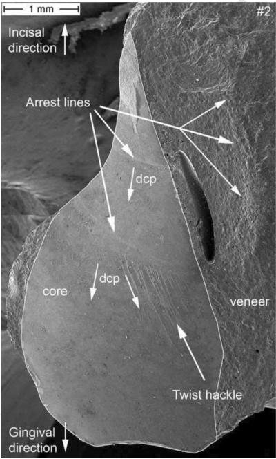
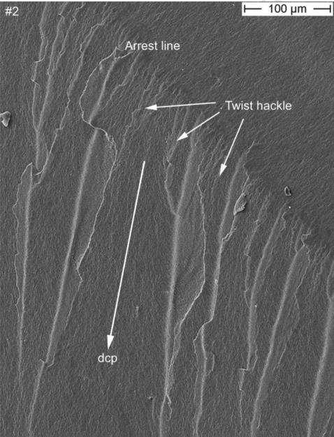
Figure 3.
SEM image of the zirconia core section of part #2. A connector area of 8.4 mm2 was measured. Fractographic features like arrest lines and twist hackle are indicated. The direction of crack propagation (dcp) is indicated. A major processing pore is seen in the veneering ceramic.
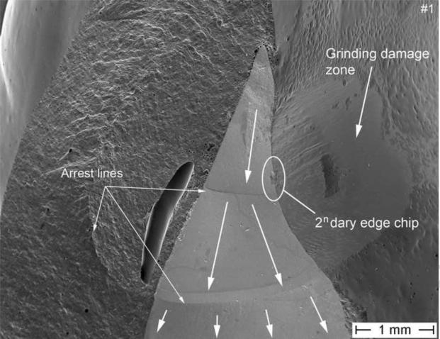
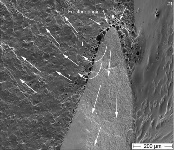
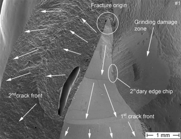
At low magnifications, two clear arrest lines and twist hackle are visible on the zirconia core as indicated by the arrows in Figure 3. These two easily seen features provide already a clear indication as to the dcp which is running from top (incisal) to bottom (gingival). Indeed, the arrest lines are perpendicular to the crack propagation and the origin of the crack is located on the concave side of the first arrest line, which means further up, near the incisal tip of the core. Next to these two arrest lines, and within the veneering ceramic is a major pore. An arrest line is in continuation with this pore but can be better seen in the matching half (part #1) in Fig. 5. This veneer arrest line represents a slowing down of the crack front soon after encountering the pore. The second feature visible in Fig. 3 and serving as an indicator of dcp are twist hackle. These are seen at higher magnification in Fig. 4 emanating from a core arrest line. They are hackle with a rotation due to a new stress direction giving them the appearance of lances as the small hackle lines merge into coarser needle like hackle lines. The dcp (arrow) is moving from incisal (top) to gingival (bottom). The second recovered broken part (Fig. 5) shows a better overall image. Three arrest lines are clearly visible on the zirconia core surface, and so is a big pore and an arrest line in the veneering ceramic. In addition, a small edge chip and a grinding damage zone on the palatal exposed zirconia frame are marked and are discussed in more detail further in the text under Fig. 7. A close-up image of the incisal tip of the zirconia frame (Fig. 6), shows the fracture origin at the tip of the zirconia core frame in form of a pore cluster within the veneering ceramic at the interface core-veneer (small arrows). Wetting of such a thin (< 200 μm) zirconia frame tip is a difficult task for the lab technician and may result in trapped air bubbles. Such a flawed core-veneer interface was seen with the pore cluster in Fig. 6. Classic fractographic features such as a fracture mirror surrounding the failure-initiating defect were not present in Fig. 6. This is not uncommon in clinical fractographic failure analyses (Thompson et al., 1994; Quinn et al., 2005; Scherrer et al., 2006; Scherrer et al., 2007) and it indicates there were either very low stresses that caused fracture, or stress gradients existed that decreased the stresses away from the origin site. The primary crack front moves downwards but is slightly perturbed at the initial stage by some surface irregularities on the fractured core surface giving rise to a secondary crack front which moves with a twist towards the buccal side within the veneering ceramic. Large arrows indicate the general dcp.
Figure 5.
SEM image of the fracture part #1 exhibiting the same arrest lines in the zirconia core as with part #2. A major processing pore is seen in the veneering ceramic. The direction of crack propagation (dcp) is indicated by the white arrows. The concavity of the arrest lines as well as the presence of twist hackle in the zirconia framework point back to an origin located at the tip of the framework (see Fig. 6). A secondary edge chip (see Fig. 7) on the zirconia palatal surface next to a manually reground zirconia frame region is indicated by the white circle.
Figure 4.
SEM image of a detailed view of the twist hackle region, indicated in Fig 3. The direction of crack propagation (dcp) is indicated by the arrow (moving downwards towards the gingival side)
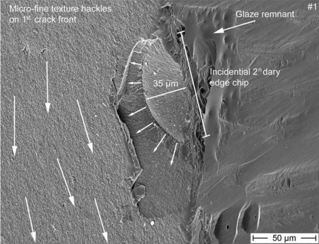
Figure 7.
SEM magnification of the secondary edge chip from Fig 5 starting on the exposed zirconia frame on the palatal surface next to some glaze remnant. The initial flaw size of the chip is of 35 μm and delimited by an arrest line. This edge chip crack is however stopped soon after as seen by the absence of hackle penetrating into the core beyond the chip size, indicating that this is a secondary event. Many micro-fine texture hackle visible in the core material are propagating downwards to the gingival margin, perpendicular to the edge chip (big white arrows).
Figure 6.
Higher magnification of Fig 5, shows the fracture origin at the tip of the zirconia core frame in form of a pore cluster within the veneering ceramic at the interface core-veneer (small arrows). The primary crack front moves from the tip downwards along the core (very fine hackle and arrest lines are visible on the core surface), whereas a secondary crack front moves with a twist direction towards the buccal side within the veneering ceramic as seen by the presence of hackle and wake hackle. The large arrows indicate the dcp.
Fig. 7 shows a higher magnification of Fig. 5 of the edge chip which started on the palatal exposed zirconia frame next to some grinding damage and next to some glaze remnants. The initial flaw size of the chip is of 35 μm and delineated by an arrest line. This edge chip crack is however stopped soon after as seen by the absence of hackle penetrating into the core beyond the chip, indicating that this is a secondary event. Indeed, many micro-fine texture hackle in the core material are propagating downwards to the gingival margin and are perpendicular to the edge chip. Those fine hackle together with the major arrest lines (Fig. 3 and 5) are clear indicators of the prime crack front (big white arrows) moving downwards towards the gum. There also is no indication whatsoever of this edge chip on the matching fracture half on part 2 shown in Figure 3, which confirms the edge chip is a secondary fracture that only occurred in part 1.
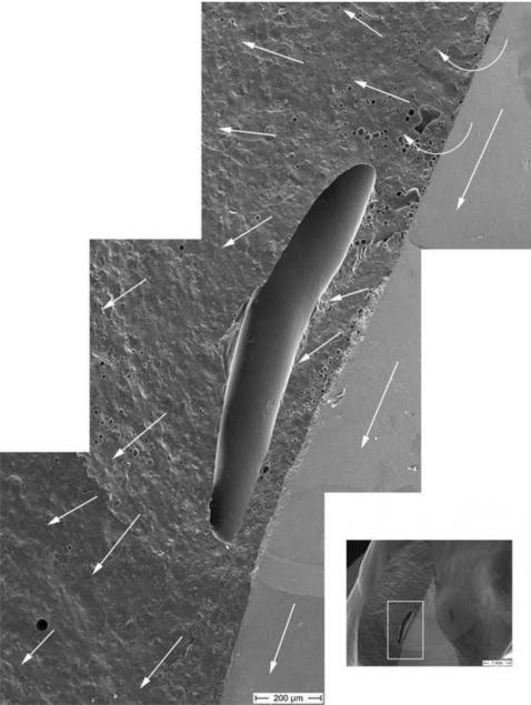
Fig. 8 provides a close-up view of the big pore in the veneering ceramic. This enormous pore is approximately 1.3 mm in length. Wake hackle emanate from tiny pores in the veneering ceramic which allow us to follow the direction of the crack front. It moved through and around the big pore in a counter clock rotation and finished parallel to the zirconia core crack front moving downwards in a gingival direction. All the above evidence show that this large pore was not the origin of fracture.
Figure 8.
This SEM photomontage shows the region of the big pore as seen in part #1. Hackle and wake hackle within the veneering ceramic indicate the direction of the crack front, contouring the big pore in a counterclock rotation. The dcp is marked with the white arrows.
4. Discussion
A six-unit bridge failure after 24 hours of intra-oral use is always a bit suspicious and thorough investigations have to be performed to understand the problem. In this case, the patient factor can be neglected to be responsible for failure, since the bridge fracture happened after the first day of provisional cementation and there were no special events reported of critical intraoral chewing during this period. Also slow crack growth or aging as fatigue mechanisms are not likely to contribute to the present clinical case in such a short in vivo period (Lohbauer et al., 2002; Studart et al., 2007). After fractographic analysis of the broken parts, several errors have been identified contributing to the early failure.
The first important observation was that fracture was in a plane perpendicular to the dental arch. From the law of normal crack propagation (Frechette, 1990; Quinn, 2007), it may be deduced that the axis of maximum principal tensile stress was parallel to the framework long axis.
The fracture surface examinations show the general direction of crack propagation as evidenced by arrest lines, hackle, twist hackle, and wake hackle, and could be mapped on the fractured parts. Fracture clearly started from the incisal tip of the palatal zirconia framework and propagated towards the cervical region in this maxillary FPD. This is somewhat surprising, since most bridge and framework fractures start from the gingival side, often at a connector, and propagate towards the palatal regions due to bending stresses generated by occlusal loading on the pontic (Oh et al., 2002; Luthy et al., 2005; Kelly et al., 1995). One likely scenario is that this 6 unit FPD was unevenly supported by the three abutments. Upward occlusal loadings on units 13 or 12 as well as upwards occlusal loadings on the other side (units 21 to 23) caused bending about unit #11 which acted as a fulcrum (or pivot point) such that tensile bending stresses developed at the incisal side of the FPD on the connector side of unit #11.
Another very likely source of the tensile stresses may be from the unbalanced thermal contraction strains, which may also have contributed to fracture. The CTE of the veneer is typically less than that of the core ceramic, so that after cool down, the veneer is in a state of residual compression and the framework material is in residual tension (Kingery et al., 1960; Taskonak et al., 2008b). In the present case, the framework is so thin at the origin location that the contraction is dominated by the thick veneer (Fig 2). The thin framework is held in tension by the veneer which contracts less. A simple estimate of the framework stresses, σf, may be made by assuming the veneer contacts fully, and thus the stress in the framework is:
| (1) |
where the framework expansion coefficient, αf, is 10.5 × 10⁻⁶ 1/K, the veneer αv, is 9.9 × 10⁻⁶ 1/K, Ef is the elastic modulus of the framework (205 GPa), and Tg is the glass transition temperature of the veneer (Tg = 565°C for a similar zirconia veneer (Taskonak et al., 2008b). This tensile stress σf, which acts in the direction of the dental arch and is perpendicular to the plane of fracture, is not large, but it will be severely concentrated around the flaws that exist at the tip of the core material. The stress concentration factor for a through hole in a plate is a factor of 3, and it is not hard to imagine even higher stress concentrations around the pore network at the fracture origin site (see Fig 6), so the residual thermal stresses could be several hundred MPa.
The crack origin itself was identified as being located at the tip of the core frame surrounded by pores resulting from poor wetting of the veneering ceramic. This drop shape design is unsuitable for a bridge frame as high stresses will concentrate at the tip if the FPB bends as described above. This is also an area subjected to occlusal contact pressure. A wider plateau design of this frame tip and in general a larger connector surface area (Filser et al., 2001) would have prevented this type of failure from the occlusal-palatal contact surface.
The volume distribution of the core/veneer is erroneous as the framework is located far too much the palatal side resulting in a high veneer volume on the buccal side and little to no veneering on the palatal side due to a lack of vertical space. Figure 2 (green line) shows a clinically recommendable framework design. Several authors have emphasized on the importance of an anatomically supportive design of the frame and appropriate core-veneer distribution (Tinschert et al., 2008; Molin and Karlsson, 2008). Usually, the unveneered framework is tried-in and checked by the dentist before moving on with the veneering. The dentist at that stage controls the occlusion and fit and will recognize any oversized framework dimensions or problematic core design. He will then proceed with the acceptance or rejection of the framework providing a feed-back to the laboratory. This try-in session was unfortunately not done in the present case and would have prevented the lab technician from further performing core adjustments through grinding as well as veneering an unsuitable core design to start with.
The zirconia framework was reshaped in the laboratory by grinding off the palatal surface due to an excessive thickness interfering with the occlusion, as seen from the grinding marks on palatal side of the broken bridge. This rough reshaping risks the introduction of critical surface damage which will lower the zirconia strength (Kosmac et al., 1999; Wang et al., 2008; Curtis et al., 2006). Such reshaping could have been prevented by a more careful and adequate computer design, aided if necessary by a wax-up of the frame.
Finally, the investigated zirconia bridge was provisionally cemented using a temporary zinc oxide-eugenol based luting material (Temp Bond®). For zirconia restorations, most manufacturers recommend conventional, retentive glass-ionomer or zinc phosphate cementation (Taskonak et al., 2008). However, superior adhesion has been reported when using tribochemical silica coating on the intaglio side of the zirconia frameworks and in combination with resin-based luting agents containing reactive monomers (pendant phosphate esters) (Leevailoj et al., 1998; Ernst et al., 2005; Blatz et al., 2003; Atsu et al., 2006). Finite element analysis support this hypothesis due an effective stress transfer between a stiff frameworks and the supporting tooth structure, when using resin luting agents (Proos et al., 2003). Such a resin-based luting procedure would have helped delay the failure event.
Figure 9.
Final mapping of the fracture event. Failure occurred from a stress concentrating zone at the tip of the zirconia framework (origin). Based on fractographic evidences (arrest lines, hackle, wake hackle, twist hackle) the crack moved in a downward direction as indicated by the arrows. A secondary edge chip on the palatal exposed zirconia framework was incidental and not related to the final failure.
Acknowledgements
This work was partially supported by National Institute for Standards and Technology, American Dental Association Foundation and National Institute of Health with grant NIH R01-DE17983.
Footnotes
Publisher's Disclaimer: This is a PDF file of an unedited manuscript that has been accepted for publication. As a service to our customers we are providing this early version of the manuscript. The manuscript will undergo copyediting, typesetting, and review of the resulting proof before it is published in its final citable form. Please note that during the production process errors may be discovered which could affect the content, and all legal disclaimers that apply to the journal pertain.
Commercial products and equipment are identified only to specify adequately experimental procedures and does not imply endorsement by the authors, institutions or organizations supporting this work, nor does it imply that they are necessarily the best for the purpose.
Conflict of Interest The authors declare that they have no conflict of interest.
References
- Aboushelib MN, Feilzer AJ, Kleverlaan CJ. Bridging the gap between clinical failure and laboratory fracture strength tests using a fractographic approach. Dent. Mater. 2009;25:383–391. doi: 10.1016/j.dental.2008.09.001. [DOI] [PubMed] [Google Scholar]
- Atsu SS, Kilicarslan MA, Kucukesmen HC, Aka PS. Effect of zirconium-oxide ceramic surface treatments on the bond strength to adhesive resin. J. Prosthet. Dent. 2006;95:430–436. doi: 10.1016/j.prosdent.2006.03.016. [DOI] [PubMed] [Google Scholar]
- Beuer F, Edelhoff D, Gernet W, Sorensen JA. Three-year clinical prospective evaluation of zirconia-based posterior fixed dental prostheses (FDPs) Clin. Oral. Investig. 2009;13:445–451. doi: 10.1007/s00784-009-0249-5. [DOI] [PubMed] [Google Scholar]
- Blatz MB, Sadan A, Kern M. Resin-ceramic bonding: a review of the literature. J. Prosthet. Dent. 2003;89:268–274. doi: 10.1067/mpr.2003.50. [DOI] [PubMed] [Google Scholar]
- Curtis AR, Wright AJ, Fleming GJP. The influence of surface modification techniques on the performance of a Y-TZP dental ceramic. J. Prosthet. Dent. 2006;34:195–206. doi: 10.1016/j.jdent.2005.06.006. [DOI] [PubMed] [Google Scholar]
- Dittmer MP, Kohorst P, Borchers L, Stiesch-Scholz M. Finite element analysis of a four-unit all-ceramic fixed partial denture. Acta. Biomater. 2009;5:1349–1355. doi: 10.1016/j.actbio.2008.11.015. [DOI] [PubMed] [Google Scholar]
- Ernst CP, Cohnen U, Stender E, Willershausen B. In vitro retentive strength of zirconium oxide ceramic crowns using different luting agents. J. Prosthet. Dent. 2005;93:551–558. doi: 10.1016/j.prosdent.2005.04.011. [DOI] [PubMed] [Google Scholar]
- Filser F, Kocher P, Weibel F, Lüthy H, Schaerer P, Gauckler LJ. Reliability and strength of all-ceramic dental restorations fabricated by direct ceramic machining (DCM) Int. J. Comp. Dent. 2001;4:89–106. [PubMed] [Google Scholar]
- Frechette VD. Advances in ceramics. vol 28. American Ceramic Society; Westerville, US: 1990. Failure analysis of brittle materials. [Google Scholar]
- Kelly JR, Tesk JA, Sorenson JA. Failure of all-ceramic fixed partial dentures in vitro and in vivo: analysis and modeling. J. Dent. Res. 1995;74:1253–1258. doi: 10.1177/00220345950740060301. [DOI] [PubMed] [Google Scholar]
- Kerschbaum T, Faber FJ, Keiner M, Hürther W, Schumacher S, Keller E. Complications with Cercon restorations in the first five years in situ. Dtsch. Zahnärztl. Z. 2009;64:81–89. [Google Scholar]
- Kingery WD, Bowen HK, Uhlmann DR. Introduction to Ceramics. 2nd ed. Wiley; New York: 1976. [Google Scholar]
- Kosmac T, Oblak C, Jevnikar P, Funduk N, Marion L. The effect of surface grinding and sandblasting on flexural strength and reliability of Y-TZP zirconia ceramic. Dent. Mater. 1999;15:426–433. doi: 10.1016/s0109-5641(99)00070-6. [DOI] [PubMed] [Google Scholar]
- Leevailoj C, Platt JA, Cochran MA, Moore BK. In vitro study of fracture incidence and compressive fracture load of all-ceramic crowns cemented with resin-modified glass ionomer and other luting agents. J. Prosthet. Dent. 1998;80:699–707. doi: 10.1016/s0022-3913(98)70058-7. [DOI] [PubMed] [Google Scholar]
- Lohbauer U, Petschelt A, Greil P. Lifetime Prediction of CAD/ CAM Dental Ceramics. J. Biomed. Mater. Res. 2002;63:780–785. doi: 10.1002/jbm.10468. [DOI] [PubMed] [Google Scholar]
- Luthy H, Filser F, Loeffel O, Schumacher M, Gauckler LJ, Hammerle CHF. Strength and reliability of four-unit all-ceramic posterior bridges. Dent. Mater. 2005;21:930–937. doi: 10.1016/j.dental.2004.11.012. [DOI] [PubMed] [Google Scholar]
- Mecholsky JJ. Fractography: determining the sites of fracture initiation. Dent. Mater. 1995;11:113–116. doi: 10.1016/0109-5641(95)80045-X. [DOI] [PubMed] [Google Scholar]
- Molin MK, Karlsson L. Five-year clinical prospective evaluation of zirconia-based Denzir 3-unit FPDs. Int. J. Prosthodont. 2008;21:223–227. [PubMed] [Google Scholar]
- Oh WS, Annusavice KJ. Effect of connector design on the fracture resistance of all-ceramic fixed partial dentures. J. Prosthet. Dent. 2002;87:536–542. doi: 10.1067/mpr.2002.123850. [DOI] [PubMed] [Google Scholar]
- Plengsombut K, Brewer JD, Monaco EA, Jr., Davis EL. Effect of two connector designs on the fracture resistance of all-ceramic core materials for fixed dental prostheses. J. Prosthet. Dent. 2009;101:166–173. doi: 10.1016/S0022-3913(09)60022-6. [DOI] [PubMed] [Google Scholar]
- Proos KA, Swain MV, Ironside J, Steven GP. Influence of core thickness on a restored crown of a first premolar using finite element analysis. Int. J. Prosthodont. 2003;16:474–480. [PubMed] [Google Scholar]
- Quinn JB, Quinn GD, Kelly JR, Scherrer SS. Fractographic analyses of three ceramic whole crown restoration failures. Dent. Mater. 2005;21:920–929. doi: 10.1016/j.dental.2005.01.006. [DOI] [PubMed] [Google Scholar]
- Quinn GD. A NIST recommended practice guide; Special Publication 960-16. National Institute of Standards and Technology; Washington, US: 2007. Fractography of ceramics and glasses. http://www.ceramics.nist.gov/pubs/practice.htm. [Google Scholar]
- Raigrodski AJ. Contemporary materials and technologies for all-ceramic fixed partial dentures: a review of the literature. J. Prosthet. Dent. 2004;92:557–562. doi: 10.1016/j.prosdent.2004.09.015. [DOI] [PubMed] [Google Scholar]
- Raigrodski AJ, Chiche GJ, Potiket N, Hochstedler JL, Mohamed SE, Billiot S, Mercante DE. The efficacy of posterior three-unit zirconium-oxide-based ceramic fixed partial dental prostheses: a prospective clinical pilot study. J. Prosthet. Dent. 2006;96:237–244. doi: 10.1016/j.prosdent.2006.08.010. [DOI] [PubMed] [Google Scholar]
- Sailer I, Fehér A, Filser F, Gauckler LJ, Lüthy H, Hämmerle CH. Five-year clinical results of zirconia frameworks for posterior fixed partial dentures. Int. J. Prosthodont. 2007;20:383–388. [PubMed] [Google Scholar]
- Scherrer SS, Quinn JB, Quinn GD, Kelly JR. Failure analysis of ceramic clinical cases using qualitative fractography. Int J Prosthodont. 2006;19:185–192. [PubMed] [Google Scholar]
- Scherrer SS, Quinn JB, Quinn GD, Wiskott HW. Fractographic ceramic failure analysis using the replica technique. Dent. Mater. 2007;23:1397–1404. doi: 10.1016/j.dental.2006.12.002. [DOI] [PMC free article] [PubMed] [Google Scholar]
- Scherrer SS, Quinn GD, Quinn JB. Fractographic failure analysis of a Procera AllCeram crown using stereo and scanning electron microscopy. Dent. Mater. 2008;24:1107–1113. doi: 10.1016/j.dental.2008.01.002. [DOI] [PMC free article] [PubMed] [Google Scholar]
- Studart AR, Filser F, Kocher P, Gauckler LJ. In vitro lifetime of dental ceramics under cyclic loading in water. Biomaterials. 2007;28:2695–2705. doi: 10.1016/j.biomaterials.2006.12.033. [DOI] [PubMed] [Google Scholar]
- Taskonak B, Yan J, Mecholsky JJ, Jr., Sertgöz A, Koçak A. Fractographic analyses of zirconia-based fixed partial dentures. Dent. Mater. 2008;24:1077–1082. doi: 10.1016/j.dental.2007.12.006. [DOI] [PubMed] [Google Scholar]
- Taskonak B, Borges GA, Mecholsky JJ, Jr., Anusavice KJ, Moore BK, Yan J. The effects of viscoelastic parameters on residual stress development in a zirconia/glass bilayer dental ceramic. Dent. Mater. 2008b;24:1149–1155. doi: 10.1016/j.dental.2008.01.004. [DOI] [PubMed] [Google Scholar]
- Thompson JY, Annusavice KJ, Naman A, Morris HF. Fracture surface characterization of clinically failed all-ceramic crowns. J. Dent. Res. 1994;73:1824–1832. doi: 10.1177/00220345940730120601. [DOI] [PubMed] [Google Scholar]
- Tinschert J, Schulze KA, Natt G, Latzke P, Heussen N, Spiekermann H. Clinical behavior of zirconia-based fixed partial dentures made of DC-Zirkon: 3-year results. Int. J. Prosthodont. 2008;21:217–222. [PubMed] [Google Scholar]
- Vult von Steyern P, Carlson P, Nilner K. All-ceramic fixed partial dentures designed according to the DC-Zirkon technique. A 2-year clinical study. J. Oral. Rehabil. 2005;32:180–187. doi: 10.1111/j.1365-2842.2004.01437.x. [DOI] [PubMed] [Google Scholar]
- Wang H, Aboushelib MN, Feilzer AJ. Strength influencing variables on CAD/CAM zirconia frameworks. Dent. Mater. 2008;24:633–638. doi: 10.1016/j.dental.2007.06.030. [DOI] [PubMed] [Google Scholar]


