Abstract
Posterior spinal instrumentation is frequently used for the treatment of spine disorders. Importantly, different requirements have to be considered for the optimal use of these systems in various clinical scenarios. In this work, we focused on the role of rods diameter on hardware’s stiffness. For this purpose, we established an in vitro model and compared the response to axial load of a posterior stabilization system, characterized by rods of different diameter (4, 5, 6 mm), with that of Dynesys®. Intuitively, the higher the stiffness of the hardware, the lower the load is transferred to the disc. However, the 4 hardware tested showed a different trend in the response to the load regimens: when increasing the load, more flexible systems display a progressive reduction in the percentage of load which is transferred to the disc while more rigid system display the opposite trend. Considering that the load which is transferred, and not by-passed by the hardware, influences the healing of a fracture; the integration of a bone graft or a cage; the fusion process, these data have a relevant impact on clinical practice and highlight features that have to be considered in the choice for the optimal posterior spinal instrumentation.
Keywords: Posterior spinal instrumentation, Dynamic stabilization, Biomechanics, In vitro testing
Introduction
Nowadays, a wide range of spinal instrumentation systems allow the surgeon to solve many challenges of spine disorders such as trauma, tumour, infection, spondylolisthesis, and instability [1, 2]. In particular, the standard surgical procedure for chronic low back pain is spinal fusion with instrumentation which has been demonstrated to be more effective than conservative care [3]. Transpedicular screw-based systems permit the surgeon to perform both stable fusion and dynamic posterior stabilization, thanks to the use of dedicated hardware. One of the most crucial topics in spine surgery is represented by the optimal mechanical properties the hardware has to present in order to achieve fracture healing, vertebral fusion, or even non-fusion stabilization, thus retaining some residual motion. In particular, by varying diameter and material, it is possible to finely modulate rods’ stiffness in a wide range of values in order to withstand weigh bearing forces according to patient’s needs. As a matter of fact, the optimal hardware stiffness requirements to obtain either a stable fusion or a dynamic stabilization are not known [4].
The aim of this study is to compare and quantify in vitro the mechanical properties of a posterior stabilization systems (Posterior Lumbar System—PLS®, Sintea Biotech S.p.A., Assago), characterized by different rods diameter (4, 5, 6 mm) and of a dynamic stabilization system (Dynesys®, Zimmer GmbH, Winterthur, Switzerland) in order to: (1) have a better understanding of the biomechanical performance of these systems; (2) optimize their design and shape; (3) establish a more precise surgical indication. For this purpose, an in vitro model has been set up, allowing to estimate how the axial load is applied and divided up between the anterior vertebral bodies and the stabilization device, and used to test the hardware object of this study in three different load regimens.
Materials and methods
Posterior spinal instrumentation
Hardware tested includes a dynamic stabilization system (Dynesys®, Zimmer GmbH, Winterthur, Switzerland) and a lumbar stabilization system with rods of 4, 5 and 6 mm (Posterior Lumbar System—PLS®, Sintea Biotech S.p.A., Assago).
Establishment of an in vitro model
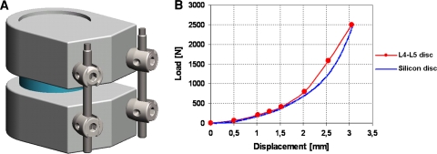
The “vertebral mobile unit” (VMU) was obtained by two vertebral bodies, a disc, and the stabilization system to be tested was applied to the VMU (Fig. 1a). The vertebral bodies were constituted of ultra high molecular weight polyethylene (UHMWPE) and shaped according to ASTM F1717-01 standard. Since the ASTM F1717-01 standard does not include the disc, the shape of the anterior part of the vertebral body was changed in order to include this structure. The disc (diameter = 40 mm; height = 10 mm) was constituted of glass fibres-loaded silicon in order to determine a stiffness comparable to that of the lumbar L4–L5 segment. The curves axial load/displacement of the L4–L5 segment were obtained from literature [5]. The trend of the curve is not linear, suggesting that the stiffness of the segment increases when a higher load is applied (Fig. 1b). As long vertebral rigidity is much higher than that of the disc, it has been assumed that all the stiffness of the system vertebra-disc-vertebra is concentrated on the disc.
Fig. 1.
a The custom VMU, built according to the ASTM F1717-01 standard. b The graph load–displacement of the disc, showing the non-linear behaviour of the human L4–L5 disc and the similar behaviour of our silicon disc
Definition of load values
The MVU was tested with a pure axial compressive load. The maximum force acting on the disc (FMaxDisc) was calculated with Nachemson correlation [6] according to the value of maximum intradiscal pressure as reported by Wilke et al. [7].
 |
where
PNucleus is pressure on the nucleus;
FDisc is the Force working on the disc which corresponds to PNucleus;
ADisc is disc area, calculated on the average dimensions of human disc [8];
k is an experimental value, which ranges from 1.3 to 1.6 for the human disc [6].
The analysis was performed at three load regimens (500, 900, 2,300 N) which correspond to different common daily activities, as summarized in Table 1 [7].
Table 1.
Load FDisc, PNucleus and corresponding level of activity [7]
| FDisc (N) | PNucleus (MPa) | Activity |
|---|---|---|
| 500 | 0.5 | Relaxed standing station Relaxed sitting on a chair without lumbar support |
| 900 | 1.1 | Sitting with the torso bent forward Standing up from a chair Climbing two stairs per time Keeping a weight of 20 kg close to the body |
| 2,300 | 2.3 | Lifting 20 kg with the torso bent forward |
Testing set-up
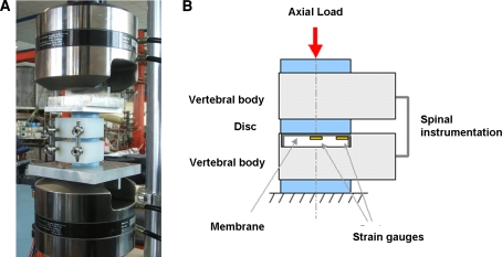
A material testing system (MTS) 858.02 Mini Bionix testing machines was used (Fig. 2a). The test was conducted at a speed of 1 mm/min. The load was applied to the VMU through two discs, similar to the one between the vertebral bodies, in order to obtain a more uniform load distribution. The compressive load also determines a bending moment acting on the stabilization device, similarly to the normal use of the system. The bending moment that acts on the rods depends from their off-set position with respect to the point of load application.
Fig. 2.
a The spine testing apparatus. b Schematic representation of the VMU and the custom pressure sensor
Applied total load and total displacement of the testing machine moving jig were measured. In order to measure the part of the load acting on the disc only, a dedicated pressure sensor was placed on the lower vertebral body. This sensor consisted in an aluminium cylinder (diameter = 40 mm), in contact with the disc, whose thin bottom (thickness = 1 mm) acts as a sensor membrane, thanks to 4 strain gauges adhesively bonded to it (Fig. 2b). Membrane deformation due to the load acting on the disc determines the deformation of the strain gauges. The value of the load was calculated through the voltage registered by the strain gauges and a calibration curve.
Results
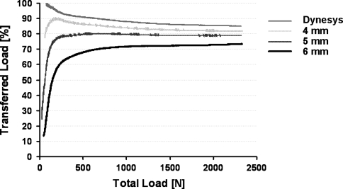
The results, obtained for the three different load regimens and for the four stabilization devices tested (five tests for each device and for each condition), are reported as transferred load to the disc (%) for the different values of total load (N) and summarized in Table 2. Data are reported as mean values ± standard deviation (SD). In addition, the curve transferred load (%) versus total load (N) depicts the trends of load distribution for each stabilization device (Fig. 3).
Table 2.
Transferred load to the disc
| Transferred load (%) | |||
|---|---|---|---|
| 500 N | 900 N | 2,300 N | |
| Dynesis | 90.3 ± 4.5 | 88.8 ± 2.7 | 85.6 ± 2.6 |
| 4 mm | 86.0 ± 3.9 | 84.3 ± 2.8 | 82.7 ± 1.7 |
| 5 mm | 79.6 ± 3.2 | 79.9 ± 1.6 | 79.1 ± 1.8 |
| 6 mm | 67.9 ± 1.4 | 71.4 ± 2.5 | 73.4 ± 0.9 |
Reported values are the mean percentage of the total load which is transferred to the disc ± SD
Fig. 3.
The Transferred Load (%) versus total load (N) graph depicting the trend of the four systems during the testing
Our results show that the overall stiffness of transpedicular systems under compression is influenced by rods diameter. However, the difference among the four spinal instrumentations was less evident at higher load. In details, at a load regimen of 500 N (standing station), the percentage of load transferred to the disc is 86% ± 3.9 and 67.9% ± 1.4 for 4 mm rods and for 6 mm rods, respectively, while at a load regimen of 2,300 N (lifting 20 kg with the torso bent forward) these percentages changes to 82.7% ± 1.7 and 73.4% ± 0.9, respectively. At a load regimen of 900 N (standing up from a chair) rods’ behaviour was intermediate. Intuitively, Dynesis® demonstrates a higher percentage of load transferred to the disc, ranging from 90.3% ± 4.5 at 500 N to 85.6% ± 2.6 at 2,300 N. In all, at low load regimen, the higher the stability of the hardware the lower percentage of load is transferred to the disc and the higher the variability between the devices tested. On the other hand, at high load regimen, the difference between the rods is less evident with an average division between rods and disc which asymptotically tends to 80–20% (Fig. 3).
Concerning the trends of the curves, more flexible systems interestingly show a reduction in the amount of load transferred to the disc at high load regimen while more stable systems displays the opposite trend (Fig. 3).
Discussion
We showed that the mechanical features of spinal instrumentation devices are influenced by rods diameter and that, in particular, the percentage of load transferred to the disc varies according to load and to hardware stiffness. Considering that posterior spinal instrumentation is used for various disorders, characterized by different needs and expectations, these experimental data have a relevance for clinical practice.
From a clinical standpoint, a more rigid system is indicated in cases of anterior column failure, such as vertebral body fracture, when by-passing load can facilitate fracture healing [9, 10]. In this scenario, a more flexible hardware could result in excessive load on the anterior column, impairing fracture healing, leading to implant failure and, ultimately to spine deformity. On the other hand, when a cage or a bone graft is applied to the anterior column, axial load can positively affect its integration. Therefore, a less rigid system, e.g. with rods of smaller diameter, which by passes the load at a minor extent, can work as tension-band, as described by Harms et al. [11], while a more rigid hardware could result in a nonunion because of the insufficient load acting on the spine segment. A further clinical scenario to be considered is the use of posterior spinal instrumentation in osteoporotic patients, where distribution of load is crucial for a successful osteosynthesis [12]. In these patients, the optimal hardware includes: a higher number of transpedicular screws in order to distribute the load on more vertebral bodies, and less rigid rods, in order to avoid an excessive shear at the screw-bone interface. In addition, the behaviour of Dynesys® in our test, with a modest and quite constant by-pass of load on the disc, highlighted the rationale of the use of this system in the initial phases of disc degeneration, as a support to the disc, in order to allow tissue healing and recover of function [13].
A further point of interest is that the difference among the devices tested in this study (Dynesis® and 4 mm-, 5 mm-, 6 mm rods) significantly decreased at a high load condition (2,300 N). This feature can be explained considering that the overall performance of the hardware depends on two different mechanisms:
the non-linear behaviour of the disc (its stiffness increases with load) (Fig. 1a) [5, 14];
the dependency of bending stiffness of the rods by their distance from load resultant.
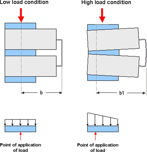
For this reason, at low load regimen (500 N), when the point of application of the load resultant corresponds to the centre of gravity of the disc, the disc itself is, therefore, uniformly loaded. Since in this case, the distance of the rods from the point of application of the load resultant is low, the non-linear behaviour of the disc determines the final behaviour of the system. On the other hand, at high load regimen (2,300 N), the presence of the rods induces a wedge deformation of the disc and a trapezoidal distribution of the load (Fig. 4). Consequently, the point of application of the load resultant moves forward and its distance from the rods increases: in this condition the bending efficiency of the rods is higher and they can withstand more load than predicted. With more flexible rods, barycentre displacement is higher, thus involving more the rods and unloading the disc; with stiffer rods, barycentre displacement is lower and therefore disc involvement increases. This explains why more flexible rods display a reduction in the percentage of load transferred to the disc at higher load regimen.
Fig. 4.
Schematic representation of the response of the VMU to low and high load regimen. In particular, the picture highlights how the point of application of the load (“b”) moves forward at high load condition (“b1”, with “b1” > “b”), because of the bending of the hardware, making the system more efficient
The main limitations of this in vitro study include the fact that the experimental set up was based only on axial load forces, while in vivo biomechanics of the spine is more complex; and that only one variable, rods diameter, has been considered, while the clinical scenario is characterized also by bone quality, number of transpedicular screws, and screws diameter. However, these data highlight the fundamental aspects of the biomechanical behaviour of posterior spinal instrumentation which can improve the knowledge and the indications of these procedures.
Conflict of interest
None.
References
- 1.Hanley EN. The indications for lumbar spinal fusion with and without instrumentation. Spine (Phila Pa 1976) 1995;20(24 Suppl):143S–153S. [PubMed] [Google Scholar]
- 2.Sonntag VK, Marciano FF. Is fusion indicated for lumbar spinal disorders? Spine (Phila Pa 1976) 1995;20(24 Suppl):138S–142S. [PubMed] [Google Scholar]
- 3.Fritzell P, Hägg O, Wessberg P, Nordwall A, Swedish Lumbar Spine Study Group 2001 Volvo Award Winner in Clinical Studies: Lumbar fusion versus nonsurgical treatment for chronic low back pain: a multicenter randomized controlled trial from the Swedish Lumbar Spine Study Group. Spine (Phila Pa 1976) 2001;26(23):2521–2532. doi: 10.1097/00007632-200112010-00002. [DOI] [PubMed] [Google Scholar]
- 4.Park WM, Park YS, Kim K, Kim YH. Biomechanical comparison of instrumentation techniques in treatment of toracolumbar burst fractures: a finite element analysis. J Orthop Sci. 2009;14(4):443–449. doi: 10.1007/s00776-009-1341-z. [DOI] [PubMed] [Google Scholar]
- 5.Brown T, Hansen RJ, Yorra AJ (1957) Some mechanical tests on the lumbosacral spine with particular reference to the intervertebral discs; a preliminary report. J Bone Joint Surg Am 39-A(5):1135–1164 [PubMed]
- 6.Cripton PA, Jain GM, Wittenberg RH, Nolte LP. Load-sharing characteristics of stabilized lumbar spine segments. Spine (Phila Pa 1976) 2000;25(2):170–179. doi: 10.1097/00007632-200001150-00006. [DOI] [PubMed] [Google Scholar]
- 7.Wilke HJ, Neef P, Caimi M, Hoogland T, Claes LE. New in vivo measurements of pressures in the intervertebral disc in daily life. Spine (Phila Pa 1976) 1999;24(8):755–762. doi: 10.1097/00007632-199904150-00005. [DOI] [PubMed] [Google Scholar]
- 8.Wolf A, Shoham M, Michael S, Moshe R. Morphometric study of the human lumbar spine for operation-workspace specifications. Spine (Phila Pa 1976) 2001;26(22):2472–2477. doi: 10.1097/00007632-200111150-00015. [DOI] [PubMed] [Google Scholar]
- 9.Mikles MR, Stchur RP, Graziano GP. Posterior instrumentation for thoracolumbar fractures. J Am Acad Orthop Surg. 2004;12(6):424–435. doi: 10.5435/00124635-200411000-00007. [DOI] [PubMed] [Google Scholar]
- 10.Parker JW, Lane JR, Karaikovic EE, Gaines RW. Successful short-segment instrumentation and fusion for thoracolumbar spine fractures: a consecutive 41/2-year series. Spine (Phila Pa 1976) 2000;25(9):1157–1170. doi: 10.1097/00007632-200005010-00018. [DOI] [PubMed] [Google Scholar]
- 11.Harms J, Stoltze D. The indications and principles of correction of post traumatic deformities. Eur Spine J. 1992;1(3):142–151. doi: 10.1007/BF00301304. [DOI] [PubMed] [Google Scholar]
- 12.Hu SS. Internal fixation in the osteoporotic spine. Spine (Phila Pa 1976) 1997;22(24 Suppl):43S–48S. doi: 10.1097/00007632-199712151-00008. [DOI] [PubMed] [Google Scholar]
- 13.Stoll TM, Dubois G, Schwarzenbach O. The dynamic neutralization system for the spine: a multi-center study of a novel non-fusion system. Eur Spine J. 2002;11(2 Suppl):S170–S178. doi: 10.1007/s00586-002-0438-2. [DOI] [PMC free article] [PubMed] [Google Scholar]
- 14.Buckwalter JA, Mow VC, Boden SD, Eyre DR, Weidenbaum M (1999) Intervertebral disk structure, composition, and mechanical function. In: Buckwalter JA, Einhorn TA, Simon SR (eds) Orthopaedic Basic Science, 2nd edn. AAOS, USA, pp 551–555


