Abstract
In vivo, neurons form neurites, one of which develops into the axon while others become dendrites. While this neuritogenesis process is well programmed in vivo, there are limited methods to control the number and location of neurite extension in vitro. Here we report a method to control neuritogenesis by confining neurons in specific regions using cell resistant poly(oligoethyleneglycol methacrylate-co-methacrylic acid (OEGMA-co-MA)) or poly(ethyleneglycol-block-lactic acid) PEG-PLA. Line patterned substrates reduce multiple extension of neurites and stimulate bi-directional neurite budding for PC12 and cortical neurons. PC12 cells on 20 and 30 µm line patterns extended one neurite in each direction along the line pattern while cortical neuron on 20 and 30 µm line patterns extended one or two neurites in each direction along the line pattern. Statistical analysis of neurite lengths revealed that PC12 cells and cortical neurons on line patterns extend longer neurites. The ability to guide formation of neurites on patterned substrates is useful for generating neural networks and promoting neurite elongation.
Keywords: Microcontact printing, Neuritogenesis, PC12 cells, Cortical neurons, Neurite extension
INTRODUCTION
The complex architecture of the neuronal network, involving over a trillion interconnected neurons in humans, underlies the proper function of the nervous system. To form the appropriate neuronal architecture in vivo, neurons extend and orient neuritis to form connections with neighboring neurons. Various cell-cell and cell-extracellular matrix adhesion molecules and soluble factors modulate this neurite outgrowth process1. Neuritogenesis involves three stages. Responding to some morphological changes, neurons first form a bud on their cell surface. From these buds on the cell membrane, sprout neurites that form one axon and multiple dendrites2. The end of each neurite is led by a growth cone, which migrates to its targets guided by the physical and chemical cues in the environment3.
Neuritogenesis, the formation of neurites, in vitro is completely different from that occurring in vivo. In vivo, early neuronal cells break their membranes to send out one axon, which guides the neurons to migrate to their synaptic destination. Once the migrating neuron axon reaches its synaptic target, the neuronal sphere breaks again to form multiple dendrites. In vitro, cultured neurons (e.g., hippocampus, hypothalamus, cerebellum) each extend multiple undifferentiated neurites within 24 hours of cell attachment after which one neurite differentiates to become the axon and the remaining neurites become dendrites4,5. The substrate surface energy6,7, chemistry8,9, compliance 10,11, and topography12,13 are the major factors that influence the differentiation process. Initial budding process is also affected by gradients of chemotactic cues such as neurotrophic factors (e.g., nerve growth factors)14 or extracellular matrix proteins (e.g., laminin and collagen)15. Esch and colleagues16 showed that hippocampal neurons extend axons preferentially into regions containing laminin but not poly-lysine. Direct mechanical tension applied using micropipettes onto hippocampal neurons have also been shown to promote neurite extension17.
The microcontact printing method for patterning cells using extracellular matrix proteins developed by Whitesides and coworkers18 have also been applied in elegant studies to control the spatial orientation of neuronal cells and neuronal associated cells 19–22 on gold coated substrate or silicon wafers. Stenger et al.21 showed that axonal/dendritic polarity in cultured hippocampal neurons can be controlled by culturing cells on substrates patterned with cell-adhesive aminosilane and cell-resistant silane. Studies conducted using cell-adhesive regions of laminin adhesive peptides YIGSR, RGD, and IKVAV and cell-repulsive regions of polyethylene glycol showed that hippocampal neurons attached and extended neurites preferentially towards peptide-functionalized regions23.
To apply cell-patterning techniques to biomaterials, we have developed a polyelectrolyte-based patterning technique. In this approach, cell-resistant random copolymers of oligo(ethylene glycol) methacrylate (OEGMA) and methacrylic acid (MA) are microcontact printed onto cell-adhesive substrates, e.g., chitosan, gelatin, tissue culture dishes, etc. to confine cell attachment on regions not printed with poly (OEGMA-co-MA)24, 25.
In this study, we explore the application of this method for patterning neuronal cells and examine the effects of confinement on the direction and length of extended neurites. Since the actin cytoskeleton generates the force necessary for budding, we hypothesize that budding and neurite extension may be controlled using patterned substrates to constrain the shape and cytoskeletal alignment of neuronal cells. To demonstrate this, PC12 cells (neuron-like cells derived from rat pheochromocytoma) were cultured on line-patterned gelatin substrate and rat cortical neuron on line-patterned poly-D-lysine coated tissue culture dishes to examine the effects of line confinement on neurite outgrowth. The results of this study suggest new approaches to control the direction and length of extended neurites that may be useful in forming neuronal networks for nerve regeneration26,27.
MATERIALS AND METHODS
Materials
Roswell park memorial institute (RPMI) 1640 medium with HEPES, L-glutamine, F-12 medium, fetal bovine serum, B27 supplements, neurobasal medium, penicillin, streptomycin, amphotericin B, and trypsin/EDTA were purchased from Gibco (Grand Island, NY) Nerve growth factor-β, Poly(ethylene glycol) monomethyl ether (mPEG-5000, Mn ~ 5000 Da), and gelatin from porcine skin type A 300 bloom (Cat#G2500) were obtained from Sigma (St. Louis, MO). Poly(dimethylsiloxane) (PDMS) (Sylgard 184) was obtained from Dow Corning (Midland, MI). Poly-D-lysine coated tissue culture dishes were purchased from Fisher (Pittsburg, PA). Gelatin films were prepared by casting gelatin solutions (0.2 M acetic acid) on glass slides and crosslinking with 0.5% glutaraldehyde solution in the dark at 4 C° after drying.
Synthesis of poly(OEGMA-co-MA)
Random copolymers of OEGMA and MA (Scientific Polymer Products, NY) were prepared by free radical polymerization of the respective monomers in methanol at 60°C. Polymerizations were initiated with 1 wt% (relative to monomers) 2,2’-azobis(2-amidinopropane) dihydrochloride (Wako, VA) and allowed to react for 16 hours. The monomer mass ratio was 80:20 of OEGMA:MA.
Synthesis of PEG-PLA
0.05 mM of poly(ethylene glycol) monomethyl ether (mPEG-5000, Mn ~ 5000 Da) and 69 mM of 3,6-dimethyl-1,4-dioxane-2,5-dione (lactide) were each dried by azeotropic distillation from toluene and combined with additional toluene. Following the addition of tin (II) ethyl hexanoate, the mixture was heated at reflux for 4 hours at which time the solvent was removed by distillation. The resulting solid mass was taken up a small amount of methylene chloride, then added dropwise to ether, causing PEG-PLA to precipitate as an oily solid (58%) that was isolated by suction filtration.
Micropatterning
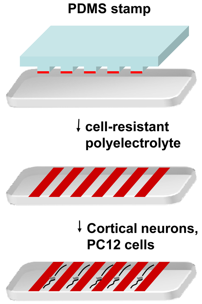
Details for fabricating the silicon master, PDMS stamps, and microcontact printing have been reported [28, 29]. Figure 1 shows the schematic of the patterning method used here. Silicon patterns with a series of 60 µm wide parallel grooves and plateaus of varying width (10, 20, and 30µm) were fabricated using standard photolithographic techniques. From this silicon master, complementary polydimethylsiloxane (PDMS) replicas were formed by pouring PDMS prepolymer (mixed in a 10:1 ratio with a cross linking catalyst) over the silicon master and curing at 55°C in an oven for 2 hours. The PDMS stamp was inked with poly(OEGMA-co-MA) or PEG-PLA solution, partially air-dried, and brought into conformal contact with gelatin films or poly-lysine coated tissue culture dishes.
Figure 1.
Schematic of the microcontact printing procedure used to pattern neuronal cells on tissue culture dishes.
Cell culture
The rat pheochromocytoma cell line, PC12, were culture in RPMI 1640 with 10% FBS, 5% horse serum, 0.25 µg ml−1 amphotericin B, 100U ml−1 penicillin, and 100 µg ml−1 streptomycin in 5% (v/v) CO2 balanced moist air at 37°C. Subconfluent cells on the tissue culture flask were dissociated using trypsin/EDTA (0.5% trypsin, 5.3 mM EDTA) and plated (2×10⁵ cells/cm2) on the patterned culture dishes. 10 ng/mL of nerve growth factor-β was added to differentiate PC 12 cells. The medium was replaced with fresh medium every 2 days.
Primary neuronal cultures were prepared from embryonic 16–18 day old Sprague-Dawley rats [30]. Rat cerebral cortex were removed from embryos and transferred to enzyme digesting solution consisting of 20 U/ml papain, 0.5 mM EDTA, and 1 mM L-cysteine in Earle’s balanced salt solution (EBSS). The tissue was mechanically disrupted and cells were collected by centrifugation. The pellet was washed and resuspended in the plating medium containing 5% horse serum and 10% fetal bovine serum in MEM supplemented with 2 mM L-glutamine. Cells were plated on poly-lysine coated tissue culture dishes with cytosine arabinoside (Ara C) in the medium. After 1 day in culture, the medium was changed to Neurobasal medium with B27 supplement (Gibco, Gaithersburg, MD) to generate pure neuronal cultures. The medium was replaced with fresh medium every 2 days.
Data analysis
Phase contrast microscope images were captured using a Spot II CCD camera and analyzed using Metamorph image processing software (Universal Imaging Westchester, PA). Neurite lengths were determined by interactive tracing of neurites. The extended structures longer than 15 µm were considered as neurites. Cells with overlapping neurites with neighboring cells were not analyzed. All experiments were repeated at least three times with independent substrates for each condition. For quantitative analysis of the effects of line confinement on neurite formation and extension, the total number of cells counted per substrate ranged from 30 to 180 cells. The mean and standard deviations for each set of data were calculated and statistical significance determined by ANOVA.
RESULTS AND DISCUSSION
Poly(OEGMA-co-MA) and PEG-PLA patterned tissue culture dishes and gelatin films are stable in culture media
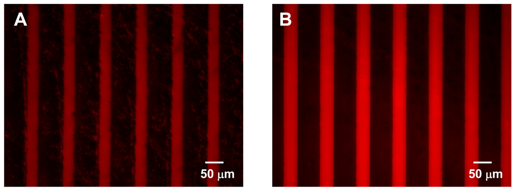
Gelatin films and poly-D-lysine coated tissue culture dishes were used in this study to pattern neuronal cells. Gelatin obtained from thermal denaturation or physical and chemical degradation of collagen has been shown to promote cell attachment [31]. Likewise, poly-D-lysine has been shown to promote adhesion of neuronal cells [32]. To demonstrate that poly(OEGMA-co-MA) and PEG-PLA resist protein adsorption and cell attachment effectively, patterned tissue culture dish and gelatin films were incubated with rhodamine-conjugated BSA. Figure 2 shows the fluorescence micrograph of rhodamine-conjugated BSA absorbed on substrates printed with a series of 60 µm wide lines of poly(OEGMA-co-MA) (Figure 2a) and PEG-PLA (Figure 2b). The 30 µm wide lines separating the line patterns of protein/cell-resistant polymers remained as gelatin (Figure 2a) and bare tissue culture dish surface (Figure 2b) and onto which BSA absorbed preferentially. The line patterns of poly(OEGMA-co-MA) and PEG-PLA are very stable and resistant to protein adsorption for more than 14 days in culture medium. The resistance of poly(OEGMA-co-MA) and PEG-PLA to protein adsorption can be attributed to the non-biofouling characteristics of the hydrated oligoethyleneglycol moieties.
Figure 2.
(A). Spatially controlled adsorption of fluorescently labeled bovine serum albumin (BSA) on a gelatin film with poly(OEGMA-co-MA) (80:20 OEGMA:MA mass ratio). 60 µm wide lines were coated with poly(OEGMA-co-MA) whereas 30 µm wide lines are unprinted. (B) Spatially controlled adsorption of fluorescently labeled bovine serum albumin (BSA) on a poly-D-lysine tissue culture dish with polyethyleneglycol-poly lactic acid (PEG-PLA). 60 µm wide lines were coated with polyethyleneglycol-poly lactic acid (PEG-PLA) whereas 30 µm wide lines are unprinted.
Line confinement promotes bi-directional neurite extension of PC12 cells
To investigate neurite protrusion and extension of geometrical confined neuronal cells, PC12 cells were cultured on poly (OEGMA-co-MA) patterned gelatin substrates with different line widths of 10, 20, and 30 µm. 10 ng/mL NGF-β was added to the medium to differentiate the PC12 cell in all cases. PC12 cells plated on 10 µm wide lines are unable to form strong adhesions and do not attach reliably compared to cells plated on 20 and 30 µm wide lines. This is likely due to the size of the PC12 cells which is larger than 10 µm. Phase contrast images of PC12 cells on 20 and 30 µm wide lines after 5 days in culture show that PC12 cells attached exclusively within the 20 and 30 µm lines not printed with poly(OEGMA-co-MA). Cells extended neurites bi-directionally along the line patterns (Figures 3A and 3B) in contrast to PC12 cells on non-patterned gelatin substrates, which extend neurites in random directions (Figure 3C).
Figure 3.
PC 12 cells following 5 days of culture on tissue culture dishes with (A) 20 µm, (B) 30 µm wide line patterns, and (C) no micropatterns.
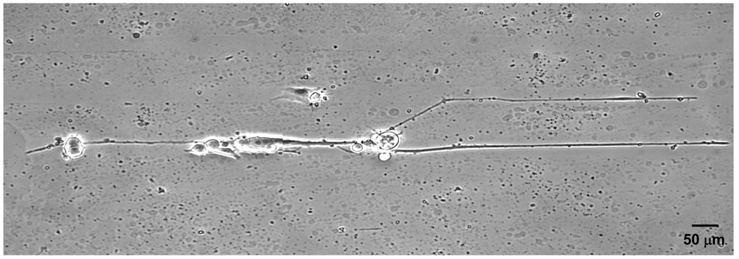
To characterize the effects of line confinement on the neurite extension of PC12 cells, we analyzed the percentage of neurite bearing neurons and analyzed the average number of neurites extended by neurite-bearing neurons (Table 1). PC 12 cells on 20 and 30 µm line pattern are more likely to extend neurites than those on non-patterned gelatin films. Patterned PC12 cells extended an average of 2 neurites, one in each direction, along the line pattern, while cells on unpatterned substrates extended on average 4.8 neurites per cell. The extension rate of neurite from PC12 cells on 20 and 30 µm line patterns were higher than those of non-patterned PC 12 cells, leading to longer neuritis for the line-patterned cells. The average neurite lengths are not reported in Table 1 because the distribution length of neurite is not normally distributed and highly skewed to short lengths. Figure 4 shows a PC12 cell attached to 30 µm wide line patterns. In this example, the cell extends one neurite to the left, and two neurites to the right, one of which has “hopped” across the 60 µm gap separating the adhesive line patterns. Since the adhesion of PC12 cells to the substratum is the same for both line-patterned and non-patterned cells, we hypothesize that the more rapid neurite outgrowth is the result of limiting the number of protruded neurites.
Table 1.
Summary of neurite extension of PC12 cells on nonpatterned and line patterned gelatin films with poly(OEGMA-co-MA). PC12 cells do not attach on 10 µm wide lines.
| Types of pattern | 20 µm | 30 µm | Non-patterned |
|---|---|---|---|
| Percentage of neurite bearing neurons | 84.6 % | 78.3 % | 67.2 % |
| Number of neuritis per neurite bearing neuron | 2.03 ± 0.13 | 2.05 ± 0.54 | 4.83 ± 1.37 |
| Longest neurite observed at day 5 (µm) | 530 µm | 565 µm | 376 µm |
Figure 4.
Pattern guided neurite extension of PC12 cells.
Line confinement influences neurite extension of cortical neurons
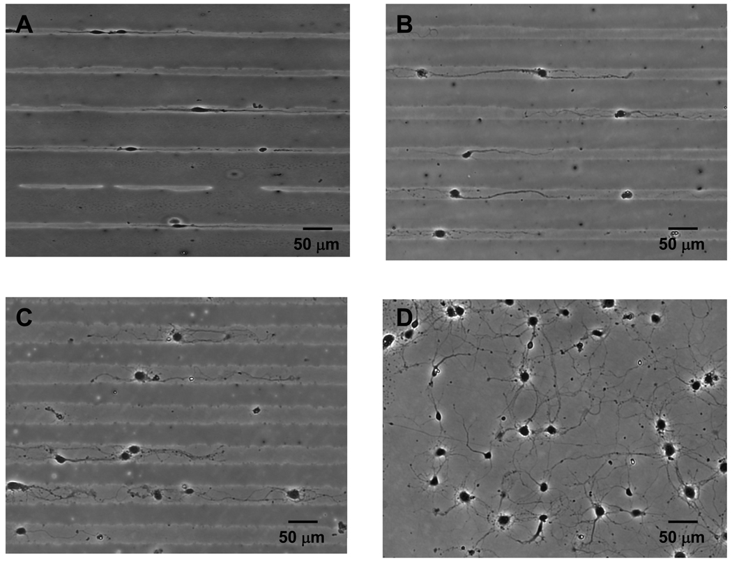
To investigate the effects of line confinement on neurite extension of cortical neurons, primary rat cortical neurons were cultured on poly-D-lysine coated culture dishes patterned with PEG-PLA. Similar to PC12 cells, these cortical neurons extended fewer neurites when confined to 10, 20, or 30 µm wide line patterns. However, unlike PC12 cells, some of which do not extend neurites, nearly all cortical neurons (>99%) extend neurites (Figures 5A–C). Most cortical neurons on 10 µm line patterns extended two neurites bi-directionally while cells on 20 and 30 µm line patterns extended more than two neurites per cell. In particular, neurites of cortical neurons on 30 µm line patterns (Figure 5C) exhibit branched elongations that are similar to neurites of cortical neurons on non-patterned poly-D-lysine dishes (Figure 5).
Figure 5.
Rat cortical neurons following 5 days of culture on tissue culture dishes with (A) 10 µm, (B) 20 µm, and (C) 30 µm wide line patterns, (D) no micropatterns.
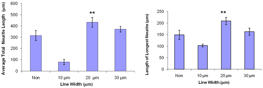
Our results shows that the line width of 20 µm is the optimal size for promoting neurite extension for cortical neurons (Figure 6). The average total length of neurites at 5 days was 315 ± 1.37 µm on non-patterned substrates (Table 2). Confinement on 10 µm lines significantly reduced average neurite length to 80 ± 23 µm while cells within 20 or 30 µm wide lines showed a higher average neurite length of 432 ± 43 µm and 370 ± 25 µm (± values represent one standard deviation). The reduced neurite extension on 10 µm wide lines is likely due to constriction of the cell nucleus. The 10 µm wide lines are much smaller than the size of the cell body and the cell is clearly elongated and constricted in this case.
Figure 6.
Analysis of neurite extension for unpatterned cortical neurons and cortical neurons on line patterns of varying widths after 5 days on the substrate. Each experiment was repeated three times on independently prepared samples and averaged for at least 100 cells. Error bars represent confidence intervals of p=0.05.
Table 2.
Summary of neurite properties of rat cortical neurons on nonpatterned and line patterned poly-D-lysine coated tissue culture dishes with PEG-PLA.
| Types of pattern | 10 µm | 20 µm | 30 µm | Non-patterned |
|---|---|---|---|---|
| Number of neurites | 1.98 ± 0.23 | 2.63 ± 0.13 | 3.85 ± 0.54 | 5.83 ± 1.37 |
| Longest neurite observed at day 5 (µm) | 103 µm | 278 µm | 230 µm | 269 µm |
CONCLUSIONS
Here we demonstrate a new approach to control the spatial distribution of neuronal cells and their neurite extension. Line confinement of PC12 cells limits neurite extension to only two per cell, one in each direction. Cortical neurons on line patterns showed significantly reduction in branching of neurites and extend neurites bi-directionally. The line patterned substrates also promote the rate of neurite extension. We investigated two separate neuronal cells with different substrate materials to demonstrate the diverse application of this methods. This approach for controlling neurite extension can also be applied directly to tissue culture dishes and other biomaterials [25,29,31,33] for generating neural networks or promoting nerve regeneration.
Acknowledgements
The authors thank the National Science Foundation and the National Institutes of Health for their support. We are grateful to Prof. Eric Gruenstein for providing the cortical neurons.
References
- 1.Da Silva JS, Dotti CG. Breaking the neuronal sphere: Regulation of the actin cytoskeleton in neuritogenesis. Nat Rev Neurosci. 2002;3(9):694–704. doi: 10.1038/nrn918. [DOI] [PubMed] [Google Scholar]
- 2.Stepanyants A, Chklovskii DB. Neurogeometry and potential synaptic connectivity. Trends Neurosci. 2005;28(7):387–394. doi: 10.1016/j.tins.2005.05.006. [DOI] [PubMed] [Google Scholar]
- 3.Maskery SM, Buettner HM, Shinbrot T. Growth cone pathfinding: a competition between deterministic and stochastic events. BMC Neurosci. 2004;5:22. doi: 10.1186/1471-2202-5-22. [DOI] [PMC free article] [PubMed] [Google Scholar]
- 4.Diaz H, Lorenzo A, Carrer HF, Caceres A. Time lapse study of neurite growth in hypothalamic dissociated neurons in culture: sex differences and estrogen effects. J Neurosci Res. 1992;33(2):266–281. doi: 10.1002/jnr.490330210. [DOI] [PubMed] [Google Scholar]
- 5.Dotti CG, Poo MM. Neuronal polarization: building fences for molecular segregation. Nat Cell Biol. 2003;5(7):591–594. doi: 10.1038/ncb0703-591b. [DOI] [PubMed] [Google Scholar]
- 6.Lamour G, Journiac N, Souès S, Bonneau S, Nassoy P, Hamraoui A. Influence of surface energy distribution on neuritogenesis. Colloilds Surf B Biointerfaces. 2009;72:208–218. doi: 10.1016/j.colsurfb.2009.04.006. [DOI] [PubMed] [Google Scholar]
- 7.Lamour G, Eftekhari-Bafrooei A, Borguet E, Souès S, Hamraoui A. Neuronal adhesion and differentiation driven by nanoscale surface free energy gradients. Biomaterials. 2010;31(14):3762–3771. doi: 10.1016/j.biomaterials.2010.01.099. [DOI] [PubMed] [Google Scholar]
- 8.Stenger DA, Pike CJ, Hickman JJ, Cotman CW. Surface determinants of neuronal survival and growth on self-assembled monolayers in culture. Brain Res. 1993;630:136–147. doi: 10.1016/0006-8993(93)90651-3. [DOI] [PubMed] [Google Scholar]
- 9.Lee MH, Brass DA, Morris R, Composto RJ, Ducheyne P. The effect of non-specific interactions on cellular adhesion using model surfaces. Biomaterials. 2005;26:1721–1730. doi: 10.1016/j.biomaterials.2004.05.026. [DOI] [PubMed] [Google Scholar]
- 10.Saha K, Keung AJ, Irwin EF, Li Y, Little L, Schaffer DV, Healy KE. Substrate modulus directs neural stem cell behavior. Biophys J. 2008;95:4426–4438. doi: 10.1529/biophysj.108.132217. [DOI] [PMC free article] [PubMed] [Google Scholar]
- 11.Teixeira AI, Ilkhanizadeh S, Wigenius JA, Duckworth JK, Inganas O, Hermanson O. The promotion of neuronal maturation on soft substrates. Biomaterials. 2009;30:4567–4572. doi: 10.1016/j.biomaterials.2009.05.013. [DOI] [PubMed] [Google Scholar]
- 12.Fan YW, Cui FZ, Hou SP, Xu QY, Chen LN, Lee IS. Culture of neural cells on silicon wafers with nano-scale surface topography. J Neurosci Methods. 2002;120:17–23. doi: 10.1016/s0165-0270(02)00181-4. [DOI] [PubMed] [Google Scholar]
- 13.Xiong Y, Lee AC, Suter DM, Lee GU. Topography and nanomechanics of live neuronal growth cones analyzed by atomic force microscopy. Biophys J. 2009;96:5060–5072. doi: 10.1016/j.bpj.2009.03.032. [DOI] [PMC free article] [PubMed] [Google Scholar]
- 14.Arevalo JC, Chao MV. Axonal growth: where neurotrophins meet Wnts. Curr Opin Cell Biol. 2005;17(2):112–115. doi: 10.1016/j.ceb.2005.01.004. [DOI] [PubMed] [Google Scholar]
- 15.Adams DN, Kao EY, Hypolite CL, Distefano MD, Hu WS, Letourneau PC. Growth cones turn and migrate up an immobilized gradient of the laminin IKVAV peptide. J Neurobiol. 2005;62(1):134–147. doi: 10.1002/neu.20075. [DOI] [PubMed] [Google Scholar]
- 16.Esch T, Lemmon V, Banker G. Local presentation of substrate molecules directs axon specification by cultured hippocampal neurons. J. Neurosci. 1999;19(15):6417–6426. doi: 10.1523/JNEUROSCI.19-15-06417.1999. [DOI] [PMC free article] [PubMed] [Google Scholar]
- 17.Lamoureux P, Ruthel G, Buxbaum RE, Heidemann SR. Mechanical tension can specify axonal fate in hippocampal neurons. J Cell Biol. 2002;159(3):499–508. doi: 10.1083/jcb.200207174. [DOI] [PMC free article] [PubMed] [Google Scholar]
- 18.Singhvi R, Kumar A, Lopez GP, Stephanopoulos GN, Wang DI, Whitesides GM, et al. Engineering cell shape and function. Science. 1994;264(5159):696–698. doi: 10.1126/science.8171320. [DOI] [PubMed] [Google Scholar]
- 19.Corey JM, Feldman EL. Substrate patterning: an emerging technology for the study of neuronal behavior. Exp Neurology. 2003;184:S89–S96. doi: 10.1016/s0014-4886(03)00392-3. [DOI] [PubMed] [Google Scholar]
- 20.Klein CL, Scholl M, Maelicke A. Neuronal networks in vitro: formation and organization on biofunctionalized surfaces. J Mater Sci Mater Med. 1999;10(12):721–727. doi: 10.1023/a:1008975105243. [DOI] [PubMed] [Google Scholar]
- 21.Stenger DA, Hickman JJ, Bateman KE, Ravenscroft MS, Ma W, Pancrazio JJ, Shaffer K, Schaffner AE, Cribbs DH, Cotman CW. Microlithographic determination of axonal/dendritic polarity in cultured hippocampal neurons. J Neurosci Methods. 1998;82(2):167–173. doi: 10.1016/s0165-0270(98)00047-8. [DOI] [PubMed] [Google Scholar]
- 22.Thompson DM, Buettner HM. Schwann cell response to micropatterned laminin surfaces. Tissue Eng. 2001;7(3):247–265. doi: 10.1089/10763270152044125. [DOI] [PubMed] [Google Scholar]
- 23.Saneinejad S, Shoichet MS. Patterned glass surfaces direct cell adhesion and process outgrowth of primary neurons of the central nervous system. J Biomed Mat Res. 1998;42(1):13–19. doi: 10.1002/(sici)1097-4636(199810)42:1<13::aid-jbm3>3.0.co;2-r. [DOI] [PubMed] [Google Scholar]
- 24.Co CC, Wang YC, Ho CC. Biocompatible micropatterning of two different cell types. J Am Chem Soc. 2005;127(6):1598–1599. doi: 10.1021/ja044382a. [DOI] [PubMed] [Google Scholar]
- 25.Kumar G, Wang YC, Co C, Ho CC. Spatially controlled cell engineering on biomaterials using polyelectrolytes. Langmuir. 2003;19(25):10550–10556. [Google Scholar]
- 26.Leach JB. Encyclopedia of biomedical engineering. Wiley; 2006. pp. 3568–3578. [Google Scholar]
- 27.Schmidt CE, Leach JB. Neuroal tissue engineering: strategies for repair and regeneration. Annu Rev of Biomed Eng. 2003;5:293–347. doi: 10.1146/annurev.bioeng.5.011303.120731. [DOI] [PubMed] [Google Scholar]
- 28.LeDuc P, Ostuni E, Whitesides G, Ingber D. Use of micropatterned adhesive surfaces for control of cell behavior. Methods Cell Biol. 2002;69:385–401. doi: 10.1016/s0091-679x(02)69024-7. [DOI] [PubMed] [Google Scholar]
- 29.Yang IH, Co CC, Ho CC. Alteration of human neuroblastoma cell morphology and neurite extension with micropatterns. Biomaterials. 2005;26(33):6599–6609. doi: 10.1016/j.biomaterials.2005.04.024. [DOI] [PubMed] [Google Scholar]
- 30.Wang X, Ciraolo G, Morris R, Gruenstein E. Identification of a neuronal endocytic pathway activated by an apolipoprotein E (apoE) receptor binding peptide. Brain Res. 1997;778(1):6–15. doi: 10.1016/s0006-8993(97)00877-9. [DOI] [PubMed] [Google Scholar]
- 31.Wang YC, Ho CC. Micropatterning of proteins and mammalian cells on biomaterials. FASEB J. 2004;18(3):525–527. doi: 10.1096/fj.03-0490fje. [DOI] [PubMed] [Google Scholar]
- 32.Corey JM, Wheeler BC, Brewer GJ. Compliance of hippocampal neurons to patterned substrate networks. J Neurosci Res. 1991;30(2):300–307. doi: 10.1002/jnr.490300204. [DOI] [PubMed] [Google Scholar]
- 33.Lin CC, Co CC, Ho CC. Micropatterning proteins and cells on polylactic acid and poly(lactide-co-glycolide) Biomaterials. 2005;26(17):3655–3662. doi: 10.1016/j.biomaterials.2004.09.051. [DOI] [PubMed] [Google Scholar]


