Abstract
A broad range of microfluidic applications, ranging from cell culture to protein crystallization, requires multilevel devices with different heights and feature sizes (from micrometers to millimeters). While state-of-the-art direct-writing techniques have been developed for creating complex three-dimensional shapes, replication molding from a multilevel template is still the preferred method for fast prototyping of microfluidic devices in the laboratory. Here, we report on a “dry and wet hybrid” technique to fabricate multilevel replication molds by combining SU-8 lithography with a dry film resist (Ordyl). We show that the two lithography protocols are chemically compatible with each other. Finally, we demonstrate the hybrid technique in two different microfluidic applications: (1) a neuron culture device with compartmentalization of different elements of a neuron and (2) a two-phase (gas-liquid) global micromixer for fast mixing of a small amount of a viscous liquid into a larger volume of a less viscous liquid.
INTRODUCTION
Multilevel microfluidic devices are used in various applications such as three-dimensional (3D) perfusion-culture of mammalian cells,1 compartmentalization of soma and axons in neuron culture,2 fabrication of 3D serpentine geometries for passive mixing,3 enhanced mixing by small topographical features,4 protein crystallization,5 and dispensing.6 Several state-of-the-art techniques have been developed for the fabrication of three-dimensional features in microdevices. Among these, interference lithography,7, 8 microstereolithography,9, 10, 11, 12 and two photon lithography13, 14 use tightly controlled photopolymerization of the device layers to build complex three-dimensional shapes. Other “direct-write” techniques include ion beam machining,15 3D writing with polymer inks,16 local electrodeposition,17 etc. While these techniques can create shapes that are not possible to build with conventional microfabrication, there is a trade-off between device complexity and the time taken to fabricate a single device. Since these techniques generate microsystems on a “one-by-one” basis using a “writing probe” with a single resolution, it is particularly time-consuming to fabricate systems with features in widely different size ranges by these techniques.
Rapid prototyping and production of a small series of identical devices are often key requirements for microfluidic applications in research laboratories. This is achieved by incorporating three-dimensional features into a replication template, from which subsequent devices are molded in a single step. Specialized techniques, such as LIGA,18 deep reactive ion etching (DRIE),19 micromilling,20 grayscale lithography,21 and solid object printing,22 have been reported in literature for fabricating multilevel masters. While LIGA, DRIE, and micromilling can lead to high resolution and aspect ratio, they need specialized expensive equipment. Grayscale lithography uses standard mask aligners, but needs an additional step with special masks (pixelated or phase masks). Solid object printing is limited to devices with large feature sizes (>200 μm). In the past, we attempted to integrate micrometer- and millimeter-sized features in replication templates by repeated mold casting in an inexpensive, but somewhat long process.23
In order to fabricate multilevel templates with standard processes and equipment, more and more groups are using successive UV lithography with different grades of SU-8.2, 4, 5, 6 While less viscous SU-8 [with viscosity of ∼7.5 cSt (Ref. 24)] is ideally suited for resolving micrometer-sized features, producing hundreds of micrometer thick layers using viscous SU-8 resists [with viscosity of ∼45 000 cSt (Ref. 25)] remains cumbersome, and an accurate reproduction of layer thicknesses is delicate.6, 26, 27, 28, 29 Slight variations in the processing conditions can cause nonuniform layer thicknesses, underexposure, insufficient baking, postprocessing mechanical stress, etc., leading to cracks or even delamination of the entire SU-8 layer. In a simpler, single-step approach, Toepke and Kenis30 fabricated multilevel structures by spin-coating a 250 μm layer of SU-8 and then utilizing the spatial dependence of the diffracted light intensity to selectively overexpose certain masked regions to form features of different heights. However, the smallest structure reported using this method is 40 μm, so the difference in height achievable by this technique is modest and is not suited to many applications.
We reported earlier31 the use of Ordyl dry film resist to fabricate embossing templates on glass and flexible plastic substrates. Dry film resists have several advantages over viscous SU-8, such as planarity over large substrate areas and simpler processing (e.g., no spin-coating, soft bake, or edge-bead removal steps). Uniform thick layers are easily obtained by multiple laminations compared to multiple spin-coating and soft-baking steps required for SU-8. We also found that Ordyl dry film has excellent adhesion to itself and most other substrates (e.g., silicon, glass, and polyethylene terephthalate), but does not require any surface pretreatment (e.g., silanization) for mold release. However, Ordyl also has some drawbacks: it has a lower resolution than SU-8 and does not allow as high aspect ratios. Small features (typically smaller than 5–10 μm) are not resolved well in dry film resists. It is possible to combine the advantages of liquid and dry resists in a multistep lithography protocol. Heuschkel et al.32 first reported the use of SU-8 and Riston dry film resist to fabricate buried microchannels for delivering solutions to neurons. However, due to weak adhesion of the Riston layer to itself, multiple laminations of the dry resist were not possible.
Here, we propose a technique addressing and overcoming the above limitations, by combining SU-8 resin with Ordyl dry film resist. We laminated and patterned two layers of Ordyl on a pre-existing SU-8 layer without any obvious adhesion problems. In addition, our approach allowed the fabrication of microsystems, combining large features (∼several hundreds of micrometers) with high resolution (∼1 μm) ones.
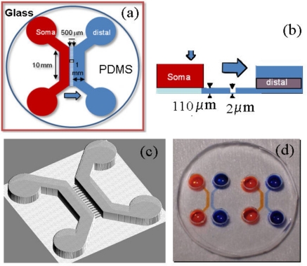
In the first application, we demonstrate a simplified approach for fabricating a neuron culture device similar to those first proposed by Taylor et al.2 This system has several different-sized channels that allow the separation of neuronal soma and dendrites from the distal parts of their axons. This is achieved by separating two cell culture chambers with an array of microchannels smaller than a cell body, but large enough to allow axons to enter. Neurons are seeded in the soma chamber and upon differentiation, they extend their axons into the microchannels and finally reach the distal chamber. The smallest features in this device (axon microchannels) are 10 μm wide and 2 μm thick, whereas the largest (soma and distal) chambers are 10 mm long, 1 mm wide, and 110 μm thick, thus making it a good candidate for hybrid lithography. We have used SU-8 to pattern high resolution microchannels and Ordyl to pattern larger chambers on the same template.
Conversely, when the smallest microstructure is no smaller than a few micrometers, it is more advantageous to fabricate the first layer of microchannels over large areas by dry film lithography and then combine it with a second layer of mesoscopic structures fabricated using liquid resin. We demonstrate this approach in a new application, a microfluidic mixer based on two-phase (gas-liquid) flows.
MATERIALS AND METHODS
Microfluidic neuron culture device: Fabrication and handling of neurons
Design of the neuron chip
The neuron culture chamber consists of three compartments (Fig. 1): a soma compartment for seeding neurons, an axonal compartment that axons only can penetrate, and a distal compartment for injecting specific reagents or seeding other types of neurons. Soma and distal compartments are 10 mm long, 1 mm wide, and 110 μm high, whereas the axonal compartment is constituted of 163 parallel channels (500 μm long, 10 μm wide, and 2 μm high) with a 20 μm separation between channels. We use SU-8 2002 to first pattern the axonal channels and then use Ordyl SY355 dry resist to pattern the larger chambers.
Figure 1.
Design of the neuron culture chip. (a) Top view of a microfluidic device, which is comprised of two individual chambers (soma and distal) separated by an array of microchannels. Soma and distal chambers are 10 mm long, 1 mm wide, and 110 μm high. These compartments are connected by 500 μm long, 10 μm wide, and 2 μm deep axonal channels (shown in blue). (b) Side view shows heights of different compartments. (c) Three-dimensional rendering of the design of the neuron chip. (d) Image of a PDMS microfluidic chip composed of two individual neuronal devices and bonded to a 5 mm glass cover slip. Different colored solutions in soma and distal chambers in both devices indicate fluidic isolation achieved by the device design.
SU-8 and Ordyl lithography
52 mm diameter and 1.5 mm thick glass substrates were obtained from Ediver (Rebais, France). These were cleaned with “Piranha” solution (75% H2SO4+25% H2O2) for 30 min, rinsed and dehydrated in an oven for 1 h at 150 °C. Just before spin-coating, the glass substrate was treated in air plasma for 1 min to improve resist adhesion.
A two-step spin-coating program (spreading spin: 5 s at 800 rpm, coating spin: 60 s at 2000 rpm) is used for SU-8 2002. The coated slides are soft-baked on a hot plate (65 °C for 2 min, followed by 95 °C for 4 min) and cooled to room temperature before 10 s of UV exposure through a transparency mask (24 500 dpi printed at Selba S. A., Versoix, Switzerland) containing the pattern of axonal compartment. Postexposure bake is carried out on a hot plate for 2 min at 65 °C, followed by 4 min at 95 °C. Following development, isopropanol rinsing, and drying, the substrates are hard-baked on a hot plate at 95 °C for 2 min.
Ordyl SY355 series dry film resist, BMR developer, and BMR rinser were obtained from Elga Europe (Italy). In the second lithography step, a 55 μm thick Ordyl Sy355 dry resist is laminated twice on the SU-8 pattern to obtain a 110 μm thick layer. Prior to lamination, the substrate is heated at 80 °C for 1–2 min on a hot plate to improve adhesion of the dry resist to the SU-8 layer. The lamination parameters of the RLM49p dry film laminator (Bundgard Electronik, Germany) are chosen as follows: pressure=0, speed=0.2 m∕min, and temperature=70 °C. A second mask containing the pattern for soma and distal chambers is aligned over the SU8 channels and following 10 s of UV exposure through the mask, the substrate is postbaked at 120 °C for 10 min on a hot plate. After development in BMR developer by gentle shaking for 5 min, the sample is rinsed with BMR rinser and isopropanol, and dried using air jet.
PDMS molding and surface treatment
Sylgard 184 parts A and B of liquid polydimethylsiloxane (PDMS) resin and curing agent were obtained from Dow Corning. 9 mg of part A (liquid PDMS resin) is mixed with 1.5 mg of part B (curing agent), degassed, poured over the hybrid replication template, and left to cure overnight at 65 °C in an oven. Access holes (3.1 mm in diameter) are punched in cured PDMS to define reservoirs. The PDMS mold and a Piranha-cleaned glass cover slip are treated in air plasma for 20 s before bonding to yield the final device.
The chip is coated overnight by filling the channels with a solution of poly-L-lysine (10 μg∕ml, Sigma) and is washed with phosphate-buffered saline (PBS) before seeding cells. This surface treatment induces neuron adhesion.2
Seeding of neurons
Cerebella are microdissected from postnatal day 5 mouse Swiss pups using a previously described protocol.33 All dissection steps are performed in cold PBS supplemented with 0.1% glucose. Dissected cerebella are digested for 10 min at 37 °C with a trypsin-ethylenediaminetetraacetic acid solution (Invitrogen) and mechanically dissociated with a Pasteur pipette in DMEM (Invitrogen) containing 10 U∕ml of DNAse-I (Sigma). After several rounds of rinsing with PBS, cells are resuspended in complete cell culture medium at a final density of 40×106 cells∕ml. Cerebellar neurons are then seeded in the soma compartment, allowed to flow to the culture chamber, and adhere within 1–2 min. Complete cell culture medium is then added equally in the four reservoirs (40 μl∕reservoir). Neurons are grown in DMEM glutamax supplemented with streptomycin∕penicillin (Invitrogen), 10% FBS, 20 mM KCl, and neuronal supplement B27 (Invitrogen). Microfluidic chips are placed in plastic Petri dishes containing water to prevent evaporation during incubation at 37 °C and 5% CO2 in a humid atmosphere. Culture medium is renewed every 3–4 days.
Immunofluorescent staining and imaging of neurons
All immunofluorescence steps are performed in the microfluidic system by flowing reagents in the cell culture chambers. After the desired time of cell culture, the neurons are fixed using a 4% paraformaldehyde solution for 10 min at room temperature. Cells are washed twice with PBS and then permeabilized with 0.2% triton X-100 and 1% BSA in PBS for 45 min at room temperature. Primary antibodies are then incubated overnight in PBS at 4 °C. Cultures are rinsed twice with PBS for 5 min each and further incubated with corresponding Alexa-coupled secondary antibodies (Invitrogen) for 2 h at room temperature. Chips are then rinsed twice with PBS and kept at 4 °C until imaging. The following primary antibodies are used: anti-β3-tubulin-FITC (mouse monoclonal, dilution 1∕700, sigma) and anti MAP2 (rabbit polyclonal, dilution 1∕400, Sigma). Cy3 labeled phalloidin (dilution 1∕700, Sigma) and DAPI (Sigma) are used to stain the actin cytoskeleton and nuclear DNA, respectively. Images are acquired with an Axio-observer Z1 (Zeiss) inverted microscope fitted with a cooled charge-coupled device (CCD) camera (CoolsnapHQ2, Roper Scientific). The microscope is controlled with MICRO-MANAGER software and images are analyzed using IMAGEJ software.
Two-phase microfluidic global mixer: Fabrication and experimental details
Principle and design of the microfluidic mixer
Most microfluidic mixers developed until now aim at fast mixing of two continuous flows of liquids using passive or active methods.34 In that framework, segmenting a flow with air bubbles induces recirculations in liquid slugs and has been shown to enhance mixing.35 However, these methods require the sample to flow for mixing to occur. Hence, these are not suitable for applications where the sample needs to be incubated in a chamber or the two samples to be mixed differ a lot in their quantities and viscosities. The latter application corresponds to the resuspension of artificial or biological macromolecules (DNA, proteins, etc.) from concentrated or lyophilized samples, for instance, for the analysis of genomic DNA. Because genomic DNA molecules are very long, in the concentrated state they form a highly entangled and viscous solution with a very long resuspension time:36 resuspension from a sample prepared by one of the conventional techniques of lyophilization or ethanol precipitation before amplification or sequencing typically takes 6–24 h. Our mixer is specifically targeted toward these applications, i.e., the mixing of a small bolus (typically ∼100 μl) of viscous sample into a larger volume (typically a few milliliters) of water or a low-viscosity buffer.
The principle of mixing in our device is based on the circulation of gas bubbles in a static chamber. It takes advantage of the recirculation induced by these bubbles without the need to move the sample into liquid slugs. This principle has been demonstrated in a microfluidic industrial prototype to improve the efficiency of DNA hybridization assays.37 However, past implementations of this mixing strategy was complicated and could use only large single bubbles. Here, we show that multiple gas bubbles are easily generated in a mesofluidic chamber using pressure pulses and can induce efficient mixing.
A large vertically positioned mixing chamber contains the liquid to be homogenized. Gas is allowed to enter the mixing chamber through a number of narrow inlet channels at the bottom and break up into bubbles, which then travel upward through the liquid exploiting buoyancy. The flow of gas bubbles causes recirculation at all length scales in the liquid and promotes mixing. In addition to disturbing the interface between two fluids, bubbles also induce long-range perturbations in the mixing chamber. During homogeneous mixing, the most viscous components of the fluid tend to be unaffected by the motion of the less viscous ones that incur most of the strain. In contrast, buoyancy dominates over viscous stress even for high viscosity fluids (high Grashof number) in our mixer, so that gas bubbles can easily distort viscous fluid components. As this device contains feature sizes ranging from tens of micrometers (inlet channels for gas) to a few millimeters (mixing chamber), we have used hybrid lithography to fabricate the replication template.
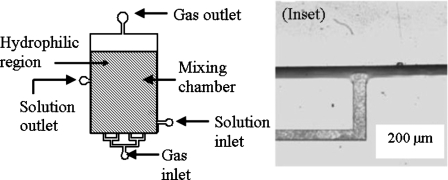
The architecture used for the two-phase mixer is shown in Fig. 2. The mixing chamber is 5 cm long, 3 cm wide, and 200 μm high. The input and output channels are 200 μm wide and 20 μm high. The inset shows an inlet channel and a portion of the mixing chamber. After filling the chamber with the liquid, gas is introduced through the bottom inlet and is discharged through the top outlet. At the end of the mixing operation, the homogenized solution is collected from the solution outlet. We have used dry film resist to fabricate the gas injection channels and SU-8 to fabricate the mixing chamber.
Figure 2.
Schematic diagram of the two-phase global mixer. The main mixing chamber has a dimension of 3 cm×5 cm and a depth of 200 μm. Each of the inlets and outlets is 200 μm wide and 20 μm deep. Surface treatment is carried out on selected parts (shaded region) of the device to make them hydrophilic. Inset: magnified image of the inlet and a part of the mixing chamber.
Combined Ordyl SY320 dry film and SU–8-2075 lithography
To fabricate the microchannels, a 20 μm thick layer of Ordyl SY320 dry resist is first laminated on the glass substrate at 0.2 m∕s and 50 °C using the RLM49p dry film laminator. After UV exposure and development, Microchem SU8-2075 is spin-coated at 1000 rpm on the dry resist-patterned wafer. UV exposure of SU-8 is carried out through a mask containing the pattern of the mixing chamber. Finally, a dual-height mold with a 200 μm high mixing chamber with straight vertical corners and 20 μm high inlet and outlet channels is obtained.
PDMS fabrication and surface treatment
The mixer is molded in PDMS, as described in Sec. 2A3. In order to avoid wall-induced coalescence of bubbles, the PDMS surface must be hydrophilic. This is achieved by the following surface treatment: a solution of 1% benzophenone in acetone is introduced into the chamber for 15 min. Acetone swells PDMS and allows the incorporation of benzophenone molecules onto the surface. Next, a 5% solution of acrylamide in water is injected into the device. UV-assisted polymerization of acrylamide is initiated in selected areas of the mixing chamber by placing the microfluidic device under a UV lamp (Biotech UV Table, 180 W) through a mask for 15 min.
Generation of bubbles and observation of flow
We operate the mixer in a vertical position. A 10% solution of glucose (with the addition of a 300 μM solution of fluorescein to visualize the flow) is mixed with a solution of water and surfactant to test the device. A nonionic surfactant (Brij 56) is added at 0.1 wt % in water in order to reduce surface tension while minimizing foam generation. 200 ms long air pulses with 7 s intervals are produced at a constant pressure by the MFCS controller (Fluigent, Paris, France) to generate bubbles.
The flow is visualized by laser induced fluorescence from the fluorescein solution (with excitation and emission maxima at 480 and 530 nm, respectively). The laser beam (473 nm and 40 mW, AOTK, Inc.) is passed through a converging lens to expand the monitoring area and then reflected by 90° using a dichroic mirror onto the device. This ensures that the entire mixing chamber is illuminated. A CCD camera oriented almost parallel to the excitation beam is used to image the flow.
RESULTS AND DISCUSSION
Compatibility of SU-8 and Ordyl dry film lithography
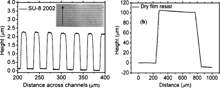
Figure 3 shows the surface profile of features obtained using SU-8 2002 and Ordyl dry film lithography. The ∼2 μm high axon compartments are well resolved in SU-8 2002. On the other hand, two successive patterns of the dry film resist lead to ∼110 μm high soma and distal chambers. In our trials we could laminate and pattern up to four layers of the dry resist (data not shown), resulting in a thickness of ∼200 μm, which indicates that the hybrid technique has the potential to fabricate devices with even higher dimension ranges.
Figure 3.
(a) Surface profile of the template for 2 μm high and 10 μm wide axon channels, with 20 μm separation between them. The inset shows an image of the channels on the template, with the arrow indicating the direction of the stylus movement. (b) Surface profile of features in Ordyl dry resist. Two successive laminations have yielded a final thickness of 110 μm.
Good contact between the transparency mask and the resist is essential to resolve micron-sized features. Hence, in each device, the layer containing the smallest features (e.g., axon compartments using SU-8 in neuron chip and inlet channels using dry resist in two-phase mixer) is patterned first. Also, visually aligning transparent SU-8 patterns in different layers can be difficult without special attention to alignment marks. The blue color of the unprocessed dry resist alleviates this difficulty in our hybrid technique.
SU-8 and Ordyl dry resist have good adhesion to each other: none of the layers delaminate during fabrication and subsequent handling. In the neuron chip, the dry film is laminated over a pattern of SU-8 2002. In the two-phase mixer, SU-8 2075 is spin-coated and processed over an existing pattern of Ordyl dry resist. The developer for one type of resist does not attack the underlying pattern of the other. Thus, the two lithography processes are chemically compatible. For both options, the different microfabrication steps involve several temperature changes. After template preparation, molding and demolding of the PDMS replicates also involve significant stresses. Typically, more than 20 replicates could be prepared from a single master without degradation, if care was taken to perform a fresh silanization every third or fourth time. Silanization is necessary for the SU-8 part and not for the dry resist. This contrasts with similar devices prepared from multiple SU-8 layers (not shown), which typically supported no more than two or three replications.
Neuron culture
Fluidic isolation between compartments in neuron chips
Our goal is to create a microfluidic device to isolate neuron somas and dendrites from their distal axonal and synaptic endings. While the array of narrow channels enables physical isolation of these neuronal subcompartments, it also isolates them chemically, thus allowing us to specifically stimulate subparts of neurons.
Two physical phenomena may induce molecular movement in microdevices: pressure-driven motion and diffusion. We estimate how these two phenomena contribute to chemical isolation of the soma and distal compartments. When a liquid is forced through a microchannel, the fluid flow rate Q is proportional to the difference of pressure ΔP between two ends of the channel. The hydraulic resistance R is defined by R=ΔP∕Q. The hydraulic resistance of a channel is proportional to μL∕wh3,38 where μ is the fluid viscosity, L is the length of the channel, w is its width, and h is its height. Here, we want to compare the hydraulic resistance of the soma or distal compartment with the resistance of a single channel of the axonal compartment. Numerical calculations with 163 parallel axon channels of 10 μm width and 10 μm separation show that the dominant effect on the hydraulic resistances is the difference in height between these two sorts of channels,
| (1) |
The hydraulic resistance set by the microchannels of the axonal compartment is thus several hundred times higher than the resistance of the soma or distal compartments. Experimentally, when a liquid is injected into the chip through the soma or distal compartments, it flows through the macrochannels and does not enter the narrow axon compartments [Fig. 1d].
However, when a chemical solution is introduced into one of the compartments, the molecules contained in the solution can also be transported to the other compartment by diffusion. The time required for a molecule to go through the microchannels from one compartment to the other under the sole effect of diffusion can be estimated by t=d2∕2D, where D is the diffusion coefficient associated with a molecule, d is the distance traveled by the molecule during a given time length t. For instance, a hemoglobin molecule with a diffusion coefficient of 7×10⁻⁷ cm2∕s would take about 30 min to traverse a 500 μm long microchannel. Therefore, we can conclude that the compartments should be chemically isolated for at least half an hour following solution injection.
When chemical isolation is needed for a longer time (e.g., for culturing neurons over days), it is reinforced by inducing a small pressure drop between the soma and distal compartments. The pressure difference is generated by filling the somatic reservoirs up to different heights. In this way, distal compartments can be supplemented by molecules intended to act on axons only, without contaminating the soma compartment. Finally, each compartment can be isolated from the other to a very good extent by introducing a small continuous flow of reagents in each of the soma and distal compartments. This ensures that the minute amounts (due to the very strong difference in flow resistances of the chambers and the axon channels) of contaminants that are likely to diffuse (or flow due to a slight pressure imbalance from one chamber to the other) are rapidly driven away by the continuous flow and remain at undetectable concentrations.
Growth of neurons in the chip
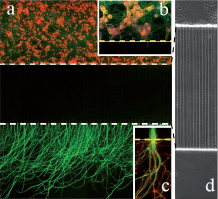
In order to demonstrate neuron culture, we studied the growth and differentiation of cerebellar granule neurons (CGNs) in the microfluidic chips. Cerebellar granule neurons are grown according to the previously described protocols33 and are composed of 95% neurons and 5% astrocytes, with less than 1% microglial cells. The number of cells seeded in the somatic compartment is approximately estimated at 30 000–40 000 cells in the area facing the microchannels. After 2 days of culture in chip, neurons begin to establish a complex network of axonal projections in the somatic compartment and some axons begin to penetrate into the first third of the thin microchannels. After 4–5 days in culture, all the thin microchannels are completely filled by growing axons which starts to reach the distal chambers. Cerebellar axons keep growing in the distal chamber to reach a maximal total length of 1000–1300 μm after 10 days of culture. Dendrites and axons can be distinguished based on their localized expression of specific proteins and respective lengths. Thus, axons are specifically stained using anti-β3-tubulin antibodies, whereas dendrites are stained with anti MAP2 antibodies. Using these criteria, we show that although dendrites can enter the microchannel, only axons can reach the distal chamber (Fig. 4), thus achieving efficient separation of the somato-dendritic compartment from the distal parts of the axons.
Figure 4.
(a) Mosaic view (40×) of a microfluidic circuit seeded CGNs and analyzed after 15 days of culture. Neurons are seeded in the soma compartment (up) and axons cross the microchannel barrier to reach the distal chamber. Cell nuclei are stained with DAPI (false red color for visibility) and axons are stained with β3-tubulin. Note the extensive axonal invasion in the distal chamber. Due to a relative loss of fluorescence signal intensity, the microchannel area (between the dotted lines) appears darker. (b) Magnification of the soma chamber next to the microchannels (dotted line). Neurons are stained with DAPI (nuclei, blue), β3-tubulin (axons, green), and MAP2 (dendrites, red). Note the excellent viability of CGN cultures after 15 days. (c) Magnification of fascicules of axons exiting a single microchannel (green: β3-tubulin; red: actin stained with phalloidin). Approximately eight individual axons can be evidenced. (d) Mosaic view of a 40× phase image of 8 day old cerebellar neurons seeded in the soma chamber (up) at lower density. Note that single axons invade the microchannels and show no sign of degeneration.
Neuronal viability was assessed using two criteria. (a) The integrity of dendritic trees was assessed by a MAP2 immunostaining. Unhealthy neurons show early signs of dentritic blebbing and dendrite retraction, while healthy neurons show regular nonfragmented dendrites. (b) The morphology of neuronal nuclei was assessed with Hoechst dye staining. Healthy neurons show homogeneous DNA staining where three to five nucleoli can be evidenced, with a nuclear diameter of approximately 7–8 μm (Fig. 4). Unhealthy neurons show nuclei with condensed chromatin (intense Hoechst staining) and small nuclear size. Using these criteria, we calculate that 99% of seeded neurons are viable after 15 days of culture. Taking care to prevent evaporation of cell culture media CGN cultures can be maintained up to a month, during which time 97% of seeded neurons show excellent viability and morphometry.
Although all seeded neurons emit axons, only a fraction of these will send their axons into the microchannels. The cerebellar granule neurons emit only one axon both in vivo and in vitro.39 By counting the number of axons exiting from the microchannel into the distal chamber, we can estimate the number of neurons that have projected their axons in the distal chamber. This ratio is around 3% and is calculated as follows: a 2 μl solution from a suspension of 40×106 neurons∕ml is flowed into the 1 μl (1 cm×0.1 cm×0.01 cm) volume of the soma chamber to seed ∼40 000 neurons in front of the microchannels. After 10 days in vitro, 5–10 axons (mean 7.5) enter each microchannel. Since 163 microchannels connect the soma and distal chambers, ∼1200 axons cross the microchannel. Morphological analysis of axons projected into the distal chamber shows that they adopt a Y-shape branching pattern, which is strikingly reminiscent of their in vivo (parallel fibers) counterpart. This indicates that cerebellar granule neurons adopt a highly polarized phenotype in our microfluidic devices.
Overall, the neuronal cell culture devices allow efficient neuronal compartmentalization. Upon high density seeding in the soma chamber, microchannels are filled quickly with axonal shafts, indicating that the neurons tolerate growth in highly constrained environments. Furthermore, the neuron chip allows excellent neuronal survival and differentiation and good fluidic isolation. Thus, the results obtained with the microchips molded from the Ordyl∕SU-8 hybrid master are compatible with the previous reports in literature, confirming that neurons tolerate PDMS environment. Compared to earlier neuron culture chips, multilevel devices allow, for the first time, an ordered and compartmentalized growth of different subcellular components and are thus a paradigmatic change, as well-discussed in Ref. 2.
Two-phase micromixer: Results and discussion
Multilevel architecture of the mixer
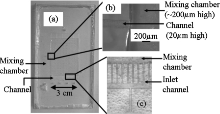
Figure 5 shows images of the two-phase global mixer molded in PDMS and its replication template. The relative heights of the input channel and the mixing chamber influence the size of the microbubbles produced in the device. Hence, a three-dimensional architecture, where the height of the mixing chamber is ten times higher than the height of the channels, is chosen and successfully fabricated using hybrid lithography. Figure 5b shows the curvature at the intersection of the channel and the mixing chamber resulting from the difference in their heights. The curvature helps in the detachment of bubbles.
Figure 5.
(a) Image of the two-phase mixing device in PDMS. (b) An enlarged view of the solution outlet in the PDMS device shows the curvature resulting from the difference in heights between the channel (20 μm) and the mixing chamber (200 μm). (c) An enlarged view of the gas inlet channels (dry resist) and the mixing chamber (SU-8) in the replication template.
Hydrophilic surface treatment and bubble formation
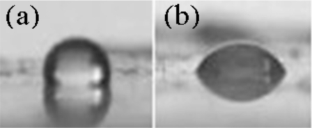
As untreated PDMS is hydrophobic, air bubbles in water tend to stick to the surface, ultimately forming a layer of air creeping on one surface, rather than small bubbles. In order to facilitate wetting of the PDMS surface by the solution and reduction of the size of the bubbles, the surface is made hydrophilic by grafting polyacrylamide molecules on the chamber walls.40 Figure 6 shows the contact angles of pure water measured on untreated and polyacrylamide-treated PDMS. The contact angle decreases from 110° to 60° following polyacrylamide treatment, indicating increased hydrophilicity of the PDMS surface.
Figure 6.
Contact angles of water on untreated and polyacrylamide-treated PDMS are shown. A drop (0.5 μl) of pure water is used to measure the contact angles. (a) Contact angle (110°) of water on untreated PDMS. (b) Contact angle (60°) of water on hydrophilic PDMS.
A mask is used to confine the polymerization of acrylamide and the resulting surface hydrophilicity to selected parts of the mixing chamber (shown by the shaded region in Fig. 2). This arrangement prevents the solution in the hydrophilic mixing chamber from escaping through the hydrophobic inlets and outlets by capillarity.
Study of bubble formation regimes
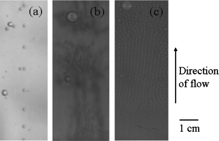
Bubble traffic must be strong for efficient mixing to take place, while avoiding formation of foam which would “freeze” the mixing process. In our system, this traffic is generated by injecting gas (air) under pressure from narrow hydrophobic microchannels into the macrochamber filled with the aqueous solutions to be mixed. We first characterize the traffic of bubbles in the chamber as a function of gas pressure. Qualitatively, three regimes are obtained, as exemplified in Fig. 7. When the pressure is progressively increased from 0, a threshold pressure of about 8 kPa is needed to overcome the Laplace pressure at the microchannel outlet. In the first regime (typically between 8 and 9 kPa pressure), a rather regularly spaced “train” of independent droplets is generated, and hydrodynamic interactions between droplets are small. In addition, generally a single train is observed [Fig. 7a]. We interpret this as a consequence of small imbalances between the geometries of the different inlet channels, which create small variations in the threshold pressures for bubble creation in each microchannel. When bubble formation at the “weakest” microchannel has started, the flow of bubbles is sufficient to release the pressure drop in the input circuitry and prevent formation of bubbles at other channels.
Figure 7.
Three regimes of device operation: (a) around 8 kPa bubble dynamics are dominated by a single, regularly spaced train of droplets, with only a few additional bubbles. (b) Droplets are generated from many microchannels. However, these are, on the average, far enough, so that their interactions are long-range hydrodynamic ones. This leads to an efficient mixing regime. Occasional coalescence leads to larger and faster droplets, which increase the multiscale character of the flow. (c) Bubbles are generated at high density, in a space-filling manner. They interact mainly by steric interactions and create a foamlike medium moving as a pseudosolid, leading to poor mixing.
Upon pressure increase, a close series of thresholds is encountered, in which an increasing number of microchannels start to generate bubbles. In this regime, hydrodynamic interactions between droplets become significant, leading to erratic trajectories of droplets and occasional droplet coalescence. This regime [Fig. 7b] is suitable for mixing (see below). More and more bubbles are produced on further increasing the pressure. This situation can lead to the formation of a foamlike medium where the interactions between droplets are mainly “hard core” steric ones [Fig. 7c]. This foam tends to push the liquid contained in the chamber as a solid, and it is not suitable for mixing. In order to optimize mixing efficiency while avoiding foam, we work in a “pulsed” mode where many bubbles are created, but are also given the time to leave the chamber. This corresponds to the results presented below.
Mixing in the pulsed mode
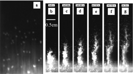
We study mixing in pulsed mode [Fig. 7b], in which hydrodynamic interactions41 between the bubbles are important enough to strongly distort their trajectory, but direct steric interactions remain infrequent. To study mixing, we fill the chamber with a first layer of dense fluid (buffer with 10% glucose) labeled with fluorescein and a second layer of pure buffer. When a bubble crosses the interface between the two fluids, it distorts the interface, and each individual bubble tends to drag a stream of viscous fluid in its wake [Fig. 8a]. If the passage of the bubble is treated as that of a sphere moving through a stationary fluid, then it creates a long-range perturbation that decays as ∼1∕r.42 Thus, the perturbation created by the bubble within the solution has a significant effect leading to mixing. We find that the efficiency of mixing can be enhanced by applying pressure in bursts. Figures 8b, 8c, 8d, 8e, 8f, 8g represent the flow following a 200 ms and 12.5 kPa pressure burst, showing the strong penetration of the dense and viscous fluid into the less viscous one. This behavior is opposite to what is expected in monophasic hydrodynamics (in which less viscous fluids can progress in a “fracturelike” manner into a more viscous one, but viscous fluids tend to push the less viscous ones in a pluglike manner).
Figure 8.
Visualization of global mixing by fluorescence. (a) Individual droplets drag the fluorescent viscous solution in their wake, creating individual streams into the less viscous fluid. [(b)–(g)] Following a pressure burst, a multiplicity of droplets in strong hydrodynamic interaction with each other is released, increasing the efficiency of mixing. Snapshots are taken at 0, 0.64, 0.8, 1.52, 2.32, and 3 s time points.
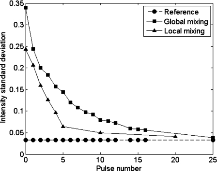
Finally, in order to quantitatively study mixing, we uniformly illuminate the whole chamber and calculate the variance σ2 and the mean standard deviation σ of the light intensity, given as
| (2) |
where I is the integrated intensity of domain x.
In order to avoid perturbations due to bubbles, all measurements are taken during the pause between pulses, when the chamber is devoid of bubbles. Figure 9 presents two measurements for the standard deviation along the vertical axis (local mixing) and the standard deviation along the horizontal axis (global mixing). The standard deviation of intensity is calculated setting bright pixels as “1” and dark pixels as “0.” Therefore, a fully segregated (unmixed) system would yield a value of 0.5, and a perfectly mixed one would yield 0 (apart from fluctuations arising from the experimental setup, such as residual inhomogeneities in illumination). These experimental artifacts are also present for the “premixed” solution, so the purple curve corresponds to the baseline for a perfectly mixed system. Mixing along the vertical is faster, as expected because of the vertical motion of the bubbles, but mixing in the transverse direction also occurs rather fast, typically in 20–25 pulses. In these experiments, in order to completely evacuate bubbles from one pulse before the next one and to allow imaging, the time delay between pulses is set to 7 s, leading to complete mixing in typically 2–3 min. However, in routine systems where bubble evacuation is not necessary, a mixing time of less than 1 min is achievable. These times are considerably shorter than those needed with conventional rotary mixers (typically overnight).
Figure 9.
Results of two mixing measurements. Squares: measurements carried out on the whole chamber width (global mixing). Triangles: measurements carried on one quarter of the chamber (“vertical” mixing, corresponding to one bubble generator).
CONCLUSIONS
An easy hybrid technique combining wet and dry lithography is reported for fabricating multilevel soft-lithography masters. The two resists (SU-8 and Ordyl) used in developing this technique have good adhesion to each other and their processing steps are compatible. The use of two different types of resins with different developing processes reduces the risk of altering the high resolution layers during the development of the thick low resolution ones. This microfabrication method is demonstrated in two applications: first, we show the possibility of fabricating replication templates for a neuron culture chip with compartmentalization of soma and axons, with high resolution microchannels. Second, we develop a new type of two-phase global mixer. We present a proof of concept of this new mixer design to show that it mixes a small bolus (∼100 μl) of a viscous, dense liquid into several milliliters of low-viscosity miscible fluid in less than 3 min, a challenge out of reach of many microfluidic systems.
ACKNOWLEDGMENTS
D. Paul acknowledges postdoctoral fellowships from IFCPAR and Curie Institute, L. Saias a Ph.D. fellowship from INCA, M. Chabert a Ph.D. fellowship from DGA, and S. Magnifico a Ph.D. fellowship from MRT. This work was partly supported by ANR “Neurosciences” and Region Ile de France, within Project “PREDICAN.”
References
- Toh Y. -C., Zhang C., Zhang J., Khong Y. M., Chang S., Samper V. D., van Noort D., Hutmacher D. W., and Yu H., Lab Chip 7, 302 (2007). 10.1039/b614872g [DOI] [PubMed] [Google Scholar]
- Taylor A. M., Rhee S. W., Tu C. H., Cribbs D. H., Cotman C. W., and Jeon N. L., Langmuir 19, 1551 (2003). 10.1021/la026417v [DOI] [PMC free article] [PubMed] [Google Scholar]
- Liu R. H., Stremler M. A., Sharp K. V., Olsen M. G., Santiago J. G., Adrian R. J., Aref H., and Beebe D. J., J. Microelectromech. Syst. 9, 190 (2000). 10.1109/84.846699 [DOI] [Google Scholar]
- Stroock A. D., Dertinger S. K. W., Ajdari A., Mezic I., Stone H. A., and Whitesides G. M., Science 295, 647 (2002). 10.1126/science.1066238 [DOI] [PubMed] [Google Scholar]
- Lounaci M., Chen Y., and Rigolet P., Microelectron. Eng. 87, 750 (2010). 10.1016/j.mee.2009.11.154 [DOI] [Google Scholar]
- Bohl B., Steger R., Zengerle R., and Koltay P., J. Micromech. Microeng. 15, 1125 (2005). 10.1088/0960-1317/15/6/002 [DOI] [Google Scholar]
- Jang J. -H. Ullal C. K., Maldovan M., Gorishnyy T., Kooi S., Koh C. Y., and Thomas E. L., Adv. Funct. Mater. 17, 3027 (2007). 10.1002/adfm.200700140 [DOI] [Google Scholar]
- Jang J. -H., Dendukuri D., Hatton T. A., Thomas E. L., and Doyle P. S., Angew. Chem., Int. Ed. 46, 9027 (2007). 10.1002/anie.200703525 [DOI] [PubMed] [Google Scholar]
- Ikuta K., Hirowatan K., and Ogata T., Proceedings of IEEE MEMS, 1994, p. 1.
- Ikuta K., Ogata T., Tsuboi M., and Kojima S., Proceedings of IEEE MEMS, 1996, p. 301.
- Bertsch A., Bernhard P., and Renaud P., Proceedings of the 8th IEEE International Conference on Emerging Technology and Automation, 2001, p. 289.
- Bertsch A., Jiguet S., and Renaud P., J. Micromech. Microeng. 14, 197 (2004). 10.1088/0960-1317/14/2/005 [DOI] [Google Scholar]
- Kawata S., Sun H. -B., Tanaka T., and Takada K., Nature (London) 412, 697 (2001). 10.1038/35089130 [DOI] [PubMed] [Google Scholar]
- Maruo S., Nakamura O., and Kawata S., Opt. Lett. 22, 132 (1997). 10.1364/OL.22.000132 [DOI] [PubMed] [Google Scholar]
- Reyntjens S. and Puers R., J. Micromech. Microeng. 10, 181 (2000). 10.1088/0960-1317/10/2/314 [DOI] [Google Scholar]
- Gratson G. M., Xu M., and Lewis J. A., Nature (London) 428, 386 (2004). 10.1038/428386a [DOI] [PubMed] [Google Scholar]
- Madden J. D. and Hunter I. W., J. Microelectromech. Syst. 5, 24 (1996). 10.1109/84.485212 [DOI] [Google Scholar]
- Malek C. K. and Saile V., Microelectron. J. 35, 131 (2004). 10.1016/j.mejo.2003.10.003 [DOI] [Google Scholar]
- Hanein Y., Schabmueller C. G. J., Holman G., Lücke P., Denton D. D., and Böhringer K. F., J. Micromech. Microeng. 13, S91 (2003). 10.1088/0960-1317/13/4/315 [DOI] [Google Scholar]
- Hupert M. L., Guy W. J., Llopis S. D., Shadpour H., Rani S., Nikitopoulos D. E., and Soper S. A., Microfluid. Nanofluid. 3, 1 (2007). 10.1007/s10404-006-0091-x [DOI] [Google Scholar]
- Galas J. C., Belier B., Aassime A., Palomo J., Bouville D., and Aubert J., J. Vac. Sci. Technol. B 22, 1160 (2004). 10.1116/1.1755213 [DOI] [Google Scholar]
- McDonald J. C., Chabinyc M. L., Metallo S. J., Anderson J. R., Stroock A. D., and Whitesides G. M., Anal. Chem. 74, 1537 (2002). 10.1021/ac010938q [DOI] [PubMed] [Google Scholar]
- Pallandre A., Pal D., de Lambert B., Viovy J. -L., and Fütterer C., J. Phys.: Condens. Matter 18, S665 (2006). 10.1088/0953-8984/18/18/S12 [DOI] [Google Scholar]
- Microchem Corporation datasheet for Nano SU-8 formulation, 2000. ⟨http://www.microchem.com/products/pdf/SU8ff2002-2025.pdf⟩.
- Processing guidelines for SU-8 2100 and 2150 from Microchem Corporation ⟨http://www.microchem.com/products/pdf/SU-82000DataSheet2100and2150Ver5.pdf⟩.
- Mata A., Fleischman A. J., and Roy S., J. Micromech. Microeng. 16, 276 (2006). 10.1088/0960-1317/16/2/012 [DOI] [Google Scholar]
- Lorenz H., Despont M., Fahrni N. Brugger J., Vettiger P., and Renaud P., Sens. Actuators, A 64, 33 (1998). 10.1016/S0924-4247(98)80055-1 [DOI] [Google Scholar]
- Peterman M. C., Huie P., Bloom D. M., and Fishman H. A., J. Micromech. Microeng. 13, 380 (2003). 10.1088/0960-1317/13/3/305 [DOI] [Google Scholar]
- Zhang J., Chan-Park M. B., and Conner S. R., Lab Chip 4, 646 (2004). 10.1039/b403304c [DOI] [PubMed] [Google Scholar]
- Toepke M. W. and Kenis J. A., J. Am. Chem. Soc. 127, 7674 (2005). 10.1021/ja050660+ [DOI] [PubMed] [Google Scholar]
- Paul D., Pallandre A., Miserere S., Weber J., and Viovy J. -L., Electrophoresis 28, 1115 (2007). 10.1002/elps.200600503 [DOI] [PubMed] [Google Scholar]
- Heuschkel M. O., Guérin L., Buisson B., Bertrand D., and Renaud P., Sens. Actuators B 48, 356 (1998). 10.1016/S0925-4005(98)00071-9 [DOI] [Google Scholar]
- Cronier S., Laude H., and Peyrin J. -M., Proc. Natl. Acad. Sci. U.S.A. 101, 12271 (2004). 10.1073/pnas.0402725101 [DOI] [PMC free article] [PubMed] [Google Scholar]
- Nguyen N. -T. and Wu Z., J. Micromech. Microeng. 15, R1 (2005). 10.1088/0960-1317/15/2/R01 [DOI] [Google Scholar]
- Garstecki P., Fuerstman M. J., Fischbach M. A., Sia S. K., and Whitesides G. M., Lab Chip 6, 207 (2006). 10.1039/b510843h [DOI] [PubMed] [Google Scholar]
- Sambrook J. and Russell D., Molecular Cloning: A Laboratory Manual (Cold Spring Harbor Laboratory Press,New York, 2001). [Google Scholar]
- Liu R. H., Lodes M. J., Nguyen T., Siuda T., Slota M., Fuji H. S., and McShea A., Anal. Chem. 78, 4184 (2006). 10.1021/ac060450v [DOI] [PubMed] [Google Scholar]
- Beebe D. J., Mensing G. A., and Walker G. M., Annu. Rev. Biomed. Eng. 4, 261 (2002). 10.1146/annurev.bioeng.4.112601.125916 [DOI] [PubMed] [Google Scholar]
- Hatten M. E., Lynch M., Rydel R. E., Sanchez J., Josephs-Silverstein J., Moscatelli D., and Rifkin D. B., Dev. Biol. 125, 280 (1988). 10.1016/0012-1606(88)90211-4 [DOI] [PubMed] [Google Scholar]
- Hu S., Ren X., Bachman M., Sims C. E., Li G. P., and Allbritton N., Anal. Chem. 74, 4117 (2002). 10.1021/ac025700w [DOI] [PubMed] [Google Scholar]
- Takemura F. and Magnaudet J., J. Fluid Mech. 495, 235 (2003). 10.1017/S0022112003006232 [DOI] [Google Scholar]
- Batchelor G. K., An Introduction to Fluid Dynamics (Cambridge University Press, Cambridge, 1967). [Google Scholar]


