Abstract
Continuum robots, which are composed of multiple concentric, precurved elastic tubes, can provide dexterity at diameters equivalent to standard surgical needles. Recent mechanics-based models of these “active cannulas” are able to accurately describe the curve of the robot in free space, given the preformed tube curves and the linear and angular positions of the tube bases. However, in practical applications, where the active cannula must interact with its environment or apply controlled forces, a model that accounts for deformation under external loading is required. In this paper, we apply geometrically exact rod theory to produce a forward kinematic model that accurately describes large deflections due to a general collection of externally applied point and/or distributed wrench loads. This model accommodates arbitrarily many tubes, with each having a general preshaped curve. It also describes the independent torsional deformation of the individual tubes. Experimental results are provided for both point and distributed loads. Average tip error under load was 2.91 mm (1.5%–3% of total robot length), which is similar to the accuracy of existing free-space models.
Index Terms: Active cannula, concentric-tube robot, continuum robot, Cosserat-rod theory
I. Introduction
Concentric-tube continuum robots, which are also called active cannulas due to their promise in interventional medicine, use the geometry and elastic interaction of precurved concentric tubes to achieve a wide variety shaft curves and end-effector poses. As shown in Fig. 1, the shape of the cannula’s telescoping backbone can be changed by axially rotating and translating each individual tube at its base. Harnessing precurvature in this manner enables a larger variety of shapes at smaller diameters than is possible with continuum robots actuated by mechanisms external to the backbone (e.g., cables, pushrods, etc.). These characteristics have led to many proposed minimally invasive surgical applications for active cannulas, including use in fetal procedures [2], the lung [3], the heart [4], and in transnasal and transgastric surgeries [5], among other interventions. While some of these applications, such as manipulating a fiber-optic laser in the lung [6], may be approachable with free-space kinematic models that do not include external loading, in many other foreseeable applications, it will be useful for the cannula to intentionally manipulate tissue by retracting it, cutting it, dissecting it, traveling through it like a needle, etc. Furthermore, as the cannula approaches the area in which it is to work, it is likely that tissue will contact it at one or more points along its shaft. Gravity can also cause some (albeit typically small) deflection in an active cannula. To enable accurate control of cannula position and applied forces under these conditions, it is essential to have a model that describes cannula shape under externally applied point and distributed forces and moments.
Fig. 1.
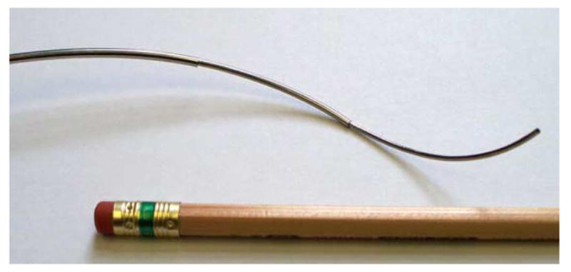
Active cannula composed of three telescoping Nitinol tubes, which is actuated by rotating and translating the tubes at their bases.
The value of modeling external loading has recently been demonstrated in larger scale pneumatically actuated continuum robots where the robot sags significantly under the self-weight of the arm. Trivedi et al. used geometrically exact Cosserat-rod theory to describe the shape of the OctArm under load, thereby reducing model errors from 50% to 5% [7]. With respect to small-scale continuum robots for medical applications, Xu and Simaan have recently demonstrated intrinsic-force sensing using a flexible push–pull-rod-actuated multibackbone robot and applied it to palpation [8]. The model that we present here may one day enable intrinsic-force sensing with active cannulas.
With respect to tendon-driven continuum robots, the effect of external loading has not yet been a focus, but rod theory has been applied to model backbone shape under tendon loads. Much of this work has built on Chirikjian’s application of continuum models to hyperredundant robots [23]. Li and Rahn formulated a geometrically exact model for the nonlinear deformation of individual sections of the backbone due to tendon loads [9]. Gravagne et al. used geometrically exact rod theory to derive the large-deflection dynamics of a planar continuum manipulator and control its vibration [10]. Camarillo et al. modeled both the bending and compression of a constant-curvature continuum robot [11]. Recently, Jones et al. explored the real-time solution of the static Cosserat-rod equations for a tendon-driven continuum robot under applied loads [12]. While our work in this paper draws upon similar geometrically exact rod theory as has been used in these studies, our concentric precurved tube design presents a fundamentally different problem because there are many elastica to consider rather than just one. While concentric tubes do share a common backbone shape, each can undergo torsion independent of the others, which precludes the use of any existing model.
While significant prior work has been done in active-cannula modeling and sophisticated free-space models exist, none have yet accounted for external forces or moments. The modeling frameworks that exist today have been developed in parallel by several groups. The simplest possible model of an active cannula by Furusho et al. [2] makes the assumption that the outermost tube in any given section of the robot has infinite stiffness compared with all tubes within it. Webster et al. [5] and Sears and Dupont [4] provided initial beam mechanics models that accounted for tube interaction and, thereby, achieved better accuracy. The importance of torsion was also recognized and initially modeled in straight sections of the device [3], [5], before being extended (in closed form) to curved sections in a two-tube cannula [13], [14]. The latest (numerically evaluated) models generalize to arbitrarily many tubes and variable precurvature [13]–[15]. While these are useful and general models, they are only able to consider cannulas in free space. Our purpose in this paper is to extend them to describe the shape of an active cannula under external loading. Such a model is a necessary prerequisite to future development in areas such as design based on compliance, manipulation of objects, and intrinsic-force sensing and control.
A. Contributions
Our contributions in this paper are as follows: 1) We present an extension of the classical, geometrically exact Kirchoff rod theory from one rod to many precurved concentric tubes under arbitrary external point and distributed wrench loading, and 2) we apply the theory to a specific active-cannula continuum robot and validate it experimentally.
Some results in this paper were presented in preliminary form in [1]. Noteworthy additions/enhancements in the current paper include the following:
an enhanced treatment of relevant results from classical Cosserat-rod theory;
derivation of the fundamental torsional component of our model using both Cosserat-rod methods and energy methods, thus demonstrating their consistency;
an expanded experimental discussion and new figures illustrating the cannula workspace, our experimental apparatus, and experimental error;
new experimental results for distributed loading;
a discussion of unmodeled effects including friction, elongation, and transverse shear, and how they could be (and whether they may need to be) included in future active-cannula models.
II. Mechanics-Based Model
Our derivations in this section draw on Antman’s thorough work on nonlinear elasticity [16, chs. 4 and 8]. In the interest of clarity to those familiar with robotics, we have replaced some of the geometric nomenclature with the more-compact kinematic notation familiar to the robotics community (e.g., the use of rotation matrices rather than directors).
This section is organized as follows. After discussing modeling assumptions in Section II-A, we proceed in Section II-B and C to introduce the kinematics and constitutive behavior of a single tube. Section II-D gives a condensed derivation of the Cosserat equilibrium equations for a precurved rod under load, the results of which provide the basis for the multitube derivation in Section II-E and F.
A. Assumptions
A theory of rod deformation is termed “geometrically exact” if it makes no approximations with respect to kinematic variables [17]. The nonexact methods typically used to predict the deformation of structural beams often employ two “small-deflection” approximations (either of which removes geometric exactness) to enable closed-form solutions: 1) The deformed shape is assumed “close” to the initial shape when computing internal stresses, and 2) some approximate formula is used for the beam’s curvature in calculating the elastic curve. In this paper, our approach is based on the geometrically exact Cosserat-rod theory, which makes neither approximation.
With respect to constitutive behavior, we use the standard assumptions of the classical elastic-rod theory of Kirchoff, which is a special case of Cosserat-rod theory [16]. The assumptions of Kirchoff are 1) inextensibility and no transverse shear strain and 2) linear constitutive equations for bending and torsion. Inextensibility and shearlessness are generally regarded to be good assumptions for long thin rods, such as the tubes in active cannulas (e.g., the prototype described in Section III). To illustrate the validity of the inextensibility assumption, we provide the following calculation. The maximum insertion force for the inner tube of our prototype was measured to be 10.1 N using an ATI Nano17 force sensor, which is a number that also exceeds any of the applied loads in our experiments. If this load was applied at both ends of a straight tube with the same dimensions as the inner tube used in our experiments, the total elongation would be less than 50 μm. Thus, we can be confident that bending and torsion will dominate the deformation behavior of an active cannula. For simplicity, we adopt the linear constitutive equations, but our overall approach does not require it. Active cannulas often remain below 3% strain in practical use, which is in the linear range of Nitinol [18].
We also neglect friction in this paper, as do all active-cannula models to date. While friction is a worthy topic of future modeling and compensation efforts, the fact that we can achieve less than 3 mm average tip error without modeling friction indicates that its effects do not dominate the behavior of our experimental prototype. Furthermore, in our experimental procedure, we explored hysteresis and noted no discernible effects, i.e., we could not induce the cannula to reach a different final position under load when the load was allowed to oscillate. We will comment further upon how frictional effects might be added to our modeling framework in Section IV.
B. Kinematics of a Single Precurved Tube
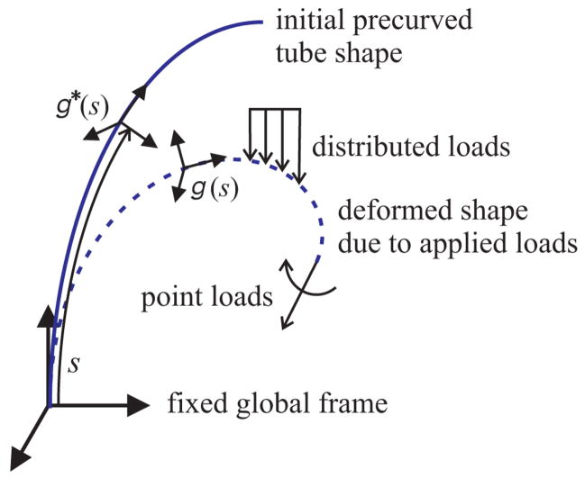
Let the unloaded precurved shape of a tube be defined by an arc-length parameterized curve r*(s).1 We assign frames continuously along r*(s) and, by convention, choose the z-axes of these frames to always be tangent to the curve (see Fig. 2 for an illustration). The well-known Frenet–Serret apparatus provides closed-form equations, which can be used to generate such frames as long as r*(s) is twice differentiable. In this convention, one axis is always aligned with the plane of instantaneous geometric curvature. Perhaps more intuitive, but less analytically simple, are rotation minimizing, or Bishop frames, which can be thought of as “sliding” along the curve without undergoing any rotation about the tangent z-axis. Both these framing conventions have been used in prior active-cannula modeling. Regardless of the convention choice (the subsequent analysis accommodates either), framing the initial tube curve creates a rotation matrix R*(s) at every arc-length location s on the undeformed curve.
Fig. 2.
The shape of a precurved rod is defined by an arc-length parameterized frame along the rod’s length. When external loads are applied, the rod deforms under a combination of bending and torsion. Since transverse shear and elongation are neglected, the frame’s z-axis remains tangent to the deformed curve.
Thus, a continuous homogeneous transformation g*(s) is established, consisting of the position and orientation of an arc-length-parameterized reference frame along the curve
| (1) |
We can obtain a local curvature vector by using the well-known relationship
Here and throughout the paper, the dot denotes a derivative with respect to arc length s. The v operator denotes conversion of an element of so(3) (the Lie algebra of SO(3)) to its corresponding element in ℝ3. Following convention, we “overload” the v notation so that it also indicates the mapping from se(3) (the Lie algebra of SE(3)) to ℝ6. The ∧ operator denotes the inverse operation in both cases. For an in-depth discussion on this notation, see [19]. Thus, the original arc-length-parameterized curve r*(s) could be reconstructed by integrating
where , and e3 = [0 0 1]T.
In Cosserat-rod theory, any deformation of a tube from its initial state g*(s) to a new state g(s) can be described by a corresponding change from ξ*(s) to ξ (s), which we denote Δξ(s) = ξ (s) – ξ*(s). The three components of Δu(s) (i.e., the change in u(s)) correspond to bending strains about the x-and y-axes of the attached local reference frame, and torsional strain about the z-axis. In general, transverse shear strain and elongation can be similarly captured by changes in the first three components of ξ (s). Since we neglect these effects in this paper (for the modeling assumptions, see Section II-A), Δu(s) completely captures the deformation of the tube. The deformed backbone shape of the tube g(s) is then defined differentially by
where , or equivalently
| (2) |
where u(s) = u*(s) + Δu(s) is the curvature vector of the deformed backbone curve.
Note that in the kinematic formulation above, one can make the following analogy to rigid-body motion: As a “body frame” angular velocity Ω describes how a rotation matrix R(t) changes with respect time [19], a local curvature vector u describes how a rotation R(s) changes with respect to the arc length of the rod. Thus, the expressions for the elastic energy stored in a deformed rod are of the same form as those for the kinetic energy of a tumbling rigid body. This is termed Kirchoff’s kinetic analog, as discussed in [20]. This analogy can be helpful for those with experience in robot dynamics to gain intuition about the model in this paper.
C. Constitutive Relationships
We use a linear constitutive law to describe the relationship of the strains to the internal moment vector (expressed in global frame coordinates) at s
| (3) |
where
E(s) is Young’s modulus, I(s) is the second moment of area of the tube cross section, G(s) is the shear modulus, and J (s) is the polar moment of inertia of the tube cross section. We use this linear relationship because it is notationally convenient and accurate for our robot, but our approach does not require it. One could easily incorporate a nonlinear constitutive law here (i.e., m = f (Δu, s)). The following model derivation would differ only in the computation of the arc-length derivative and the inverse of m.
D. Equilibrium Equations: A Single Tube Under Load
We now give a brief development of the fundamental equilibrium equations needed to obtain the deformed shape of one precurved rod under a prescribed load. Note that this exposition directly parallels the development of the multitube case in Section II-F. In [16, ch. 4.1], by writing a moment balance on a section of a rod under load then taking the derivative of the result with respect to arc length, Antman derives the equations of equilibrium for the special theory of Cosserat rods. We provide a modified, condensed version of that derivation here, which parallels the more complex development of the multitube case that follows. We will also use certain results from the single-tube analysis in the multitube development.
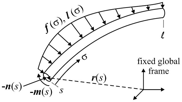
Consider a cantilevered precurved rod, the kinematics of which are described in Section II-B, extending from arc length s = 0 to s = l, and subject to an arbitrary combination of distributed forces f (s) and moments l(s) along its length. We now cut a section at an arbitrary arc-length location s, as shown in Fig. 3. By convention, we denote the internal force, which the material of [s, l] exerts on the material of [0, s), as n(s). Similarly, the internal moment that the material of [s, l] exerts on the material of [0, s) is m(s). Summing the forces on the portion [s, l], we obtain
Fig. 3.
Section of rod from s to the free end l subject to distributed forces and moments. The internal force and moment are also shown.
| (4) |
Similarly, summing the moments on the portion [s, l] about the world frame origin, we obtain
| (5) |
The unknown, deformed shape r(s) is present in both (5) and in the differential equation (2). Thus, it is not generally possible to obtain either the deformed curve or the curvature algebraically. The classical approach to solve this problem is to take derivatives of the force and moment balances with respect to arc length and then use the constitutive law to obtain derivatives of the kinematic variables that can be numerically integrated simultaneously with the kinematic equation (2) as a boundary value problem. This is the approach that we adopt here.
Taking the derivative of (4) with respect to s, we obtain
| (6) |
Similarly, taking the derivative of (5) with respect to s and substituting (6) into it yields
| (7) |
Equations (6) and (7) are the classical forms of the equations of equilibrium for a special Cosserat rod, as given in [16]. In order to obtain the deformed shape of a single rod under load, they can be expanded using (3) to obtain equations for the local curvature derivatives, which can then be integrated simultaneously with (2) (as is done, e.g., in [7] and [12]).
We now proceed to do this by expressing (6) and (7) in terms of the local curvature and kinematic framework from Section II-B. Taking the derivative of (3) and substituting (2) into it yields
| (8) |
For simplicity, we have dropped the (s) notation and will continue to do so, except where needed for clarity, for the remainder of the paper. Using (2), (4), and (8), we can rewrite (7) in terms of the curvature and the applied loads. Premultiplying by RT and K−1 and then solving for u̇, we obtain
| (9) |
This equation, combined with (2), results in a system of differential equations (u̇ and ġ in terms of u, g, and the applied loads). Typical boundary conditions for this simple case would be g(0) = g0, and mi (l) = 0 in the absence of any point moments at the tip.
E. Kinematics of a Collection of Concentric Tubes
We now consider a robot composed of a collection of precurved concentric tubes subject to a set of external forces and moments along its length. In this section, we give the geometric constraints appropriate to such a collection, and in the next section, we derive the equations of equilibrium that can be integrated to obtain the final shape of the tubes. For simplicity in deriving the fundamental equations, we consider n tubes of the same length, which are fully overlapped. In Section II-G, we will discuss how to apply the model to the case where tubes begin and end at different locations.
We assume each tube has its own arc-length-parameterized transformation , as in (1), and associated precurvature vectors , as set forth in Section II-B. If the tubes are concentric, then each of their final deformed curves must be equal, i.e., r1 (s) = r2 (s) = … = rn (s). We designate this common deformed curve as r(s). This does not imply that each gi (s) must be equal. The tubes are free to twist independently during deformation, and this prohibits us from considering the collection of concentric tubes to be a single, precurved rod.
The equality of the deformed curves can be equivalently expressed by the two statements r1 (0) = r2 (0) = … = rn (0) and ṙ1 (s) = ṙ 2 (s) = … = ṙ n (s). Thus, their tangent vectors are equal along the length. Recalling from (2) that ṙi (s) = Ri (s)e3, this implies that the third columns of each Ri (s) are equal. Therefore, each Ri (s) differs from the others by a rotation about the local tangent z-axis. We introduce an angle θi (s) to parameterize this difference as
| (10) |
where Rθi = eê3 θ i (s) denotes a rotation about the z-axis by θi (s), and θ1 ≡ 0 by definition. We use this to obtain a relationship between the tube curvature vectors that enforces the tangency constraint. Applying the definition of ui, we obtain
| (11) |
Interpreted geometrically, this equation says that the local x and y curvatures of each deformed tube are equal when expressed in a common reference frame. The torsional z components are free to vary independently for each tube. The variable θi provides a parameterization of this variance as
| (12) |
F. Equilibrium Equations: A Collection of Tubes Under Load
We now proceed to derive the equilibrium equations for a collection of concentric tubes under applied external forces and moments. This section will parallel the derivation of Section II-D. We begin by writing a force balance on a section of the cannula from arc length s to the end l
| (13) |
Similarly, summing the moments on the portion [s, l] about the world frame origin, we obtain
| (14) |
where fi and li are external force and moment distributions, respectively, applied specifically to tube i.
Taking the derivative of (13) with respect to s, we obtain
| (15) |
Similarly, taking the derivative of (14) with respect to s and substituting (15) into it yields
| (16) |
Equations (15) and (16) are the multitube analogs of the Cosserat equilibrium equations (6) and (7). Indeed, they are merely the sums of (6) and (7) over all the tubes. The substance of our approach lies in the following application of the concentric-tube kinematic constraints (allowing independent tube torsion) to these equations in order to obtain a set of differential equations similar to the single-tube case while introducing the minimum number of additional variables.
We now wish to expand (16) and solve for u̇1 in terms of the precurvatures, the applied loads, and the state variables. As in the single-tube case, we use the constitutive law (3) and the kinematic relationship (2) for each tube to obtain
We use ṙ = R1 e3 and (13) to obtain the last two terms of (16) in terms of the applied loads
where , and . Then, after premultiplying by and recalling that from (10), (16) becomes
| (17) |
We wish to obtain an expression for u̇1 in terms of f, l, R1, and u1,…, un; therefore, we apply the derivative of (11) as follows:
| (18) |
to eliminate u̇2,…, u̇n from (17). This substitution enables us to solve (17) for the first two components u̇1,x and u̇1,y in terms of the state variables
| (19) |
where , and |x,y denotes selection of only the first two components of a vector.
There is not enough information in (17) and (18) to similarly obtain u̇1,z. This is because our kinematic constraints allow the torsional strains of the individual tubes, i.e., ui,z, to be different, where θi parameterizes this difference. Thus, we now return to the single-tube formulation, as described in Section II-D, to obtain the behavior of the individual torsional strains.
Equation (9) describes the curvature of a single tube under a general load. Therefore, it remains true for every individual tube in an arrangement of many concentric tubes. We generally do not know a priori what forces and moments the tubes in a concentric collection apply to one another. However, noting that the third column of the matrix ê3 is all zeros, we find that the third component of u̇ is actually independent of any forces and nonaxial moments. Writing this third component for tube i, we obtain
| (20) |
The only external load appearing in this equation is the component of the distributed moment at s about the local z-axis. In a collection of concentric tubes, the assumption of no static friction between tubes implies that the tubes cannot apply such axial-moment distributions on one another. Therefore, in this equation, li represents a purely external torsional moment distribution applied specifically to tube i.2
This torsional behavior completes our multitube model so that we now have first-order state equations for the variable set {g1, u1, u2,z,…, un,z, θ2,…, θn }. The equations that define their derivatives are (2), (12), (19), and (20). The intermediate variables ui can be calculated algebraically from u1 at every step using (11).
G. Model Implementation
Challenges in practical implementation of our model include numerically dealing with point loads and the issue of tubes beginning and ending at different arc lengths. In an active cannula, all tubes are clamped to actuators at their bases and are subject to a set of applied loads along their length. Since the distributed force is integrated in (19), finite-point forces can be conveniently included in the model through the use of Dirac delta functions in the distribution. However, including finite-point moments using this method would cause (19) to become infinite at a point, and most numerical techniques are ill equipped to handle this. The same difficulty arises if tubes end at different arc lengths or if the precurvature of a tube undergoes a step change (i.e., if r*(s) is not twice differentiable at a point).
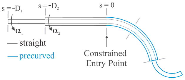
All such occurrences should ultimately result in a step change in the deformed curvature. This can be accounted for by solving a series of continuous systems bounded by the discontinuous solution points while enforcing appropriate boundary conditions at the junctions. Discontinuous solution points for a typical two-tube cannula are illustrated by gray lines perpendicular to the cannula in Fig. 4, which break it into sections. The boundary conditions to be enforced across each transition point between sections (at arc length s) are as follows: 1) The position and orientation of each tube must be continuous across the boundary, and therefore
Fig. 4.
Two-tube cannula showing transition points where continuity of shape and internal moment must be enforced. The constrained point of entry into the workspace is designated as the arc-length zero position.
and 2) static equilibrium requires that the sum of the internal moments carried by the tubes just before the end of the section equal the sum of the internal moments carried by the tubes just after the end of the section plus the sum of the applied point moments at the boundary (a point moment applied to tube i is denoted by lp,i (s)), i.e.,
This enforcement of static equilibrium across discontinuous boundaries is also required in application of Cosserat theory to other types of continuum robots, and forms of these same conditions are also given in [7].
One must also consider the boundary conditions of the entire cannula for practical implementation. In many physical prototypes of active-cannula robots, all the tubes are constrained to pass through a fixed entry point, which we designate as s = 0, as shown in Fig. 4. The actuators grasp the bases of the tubes behind this point at negative arc-length values s = −Di. At the proximal end of each tube, gi (−Di ) is determined by the actuation inputs, namely the translation and axial rotation of the base of the tube. At the distal end of the robot, the static equilibrium condition becomes
Also, at the distal end of each tube, we have a natural boundary condition for the local axial component of the internal moment of each tube
where li denotes the arc length at which tube i ends. This arises because in the absence of friction, the tubes cannot apply axial moments to one another.
The tubes are straight for s < 0, and therefore, the unknown boundary conditions on the proximal side of the robot are the set of initial curvature values {u1,x (0), u1,y (0), u1,z (−Di ), u2,z (−D2 ),…, un,z (−Dn )}. In our experiments described in the next section, we employ a standard shooting method to solve for the values of these unknown initial curvatures which satisfy the boundary conditions on the distal side while enforcing the conditions given above at each transition point.
III. Experiments
In order to validate the model developed in Section II, a set of experiments was performed for a collection of two Nitinol tubes with general precurvatures (see Fig. 5) in various configurations and under various loading conditions.
Fig. 5.
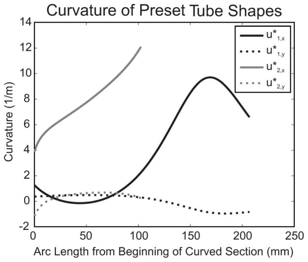
Measured curvatures of the preset tube shapes expressed in a rotation-minimizing frame (note that rotation-minimizing frames, i.e., and , are zero by definition).
A. Tube Properties and Measurement Procedures
The physical properties of the tubes used are given in Table I. Each tube has an initial straight length followed by a curved section, the curvature of which is shown in Fig. 5. In our experiments, the outer tube was held stationary in its fully extended position, while the base of the inner tube was translated to five different positions (by the actuation unit shown in Fig. 6), which are given in Table II. At each of these translational positions, the inner tube was rotated to eight evenly spaced angular positions, which are given in Table III. Thus, the tubes were actuated to 40 different workspace locations which evenly span the set of angular and linear differences of tube base positions (see Fig. 7). The rest of the configuration space could be generated by a rigid rotation of the experimentally sampled space about the base frame z-axis; therefore, this set of tube positions evenly samples the unique—from the perspective of the model—configuration space locations.
TABLE I.
Measured and Assumed Physical Quantities for Experimental Tubes
| Tube 1 (Inner) | Tube 2 (Outer) | |
|---|---|---|
| Inner Diameter (mm) | 1.25 | 2.00 |
| Outer Diameter (mm) | 1.75 | 2.37 |
| Straight Length (mm) | 122.7 | 30.7 |
| Curved Length (mm) | 206.9 | 102.5 |
| Young’s Modulus (E) (GPa) | 60 | 60 |
| Shear Modulus (J) (GPa) | 23.1 | 23.1 |
Fig. 6.

Manual actuation unit used to precisely position the bases of the tubes.
TABLE II.
Translational Actuator Configurations
| D1 (mm) | 131.7 | 154.7 | 177.7 | 200.7 | 223.7 |
| D2 (mm) | 30.7 | 30.7 | 30.7 | 30.7 | 30.7 |
| Tip Load (N) | 0.981 | 0.981 | 0.981 | 1.962 | 4.9051 |
In the α1 = 0°; α2 = 0° case the load was 1.962 N.
TABLE III.
Rotational Actuator Positions Applied at Each Translational Configuration Shown in Table II
| α1 (deg) | 0 | 451 | 90 | 135 | 180 | 225 | 270 | 315 |
| α2(deg) | 0 | 0 | 0 | 0 | 0 | 0 | 0 | 0 |
α1 = 60° was substituted for α1 = 45° when D1 = 131.7 mm to keep the tip of the cannula in the field of view of both cameras.
Fig. 7.
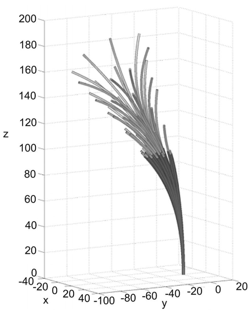
Cannula in all 40 experimental configurations. One can span the entire workspace by rigidly rotating this collection about the z-axis, which can be accomplished by rotating the base of each tube by the same amount while keeping their angular differences the same. Thus, the above illustrates a sampling of all unique configuration space locations from the model’s point of view. For each configuration, backbone data were collected in the unloaded state and with a force applied to the tip of the cannula.
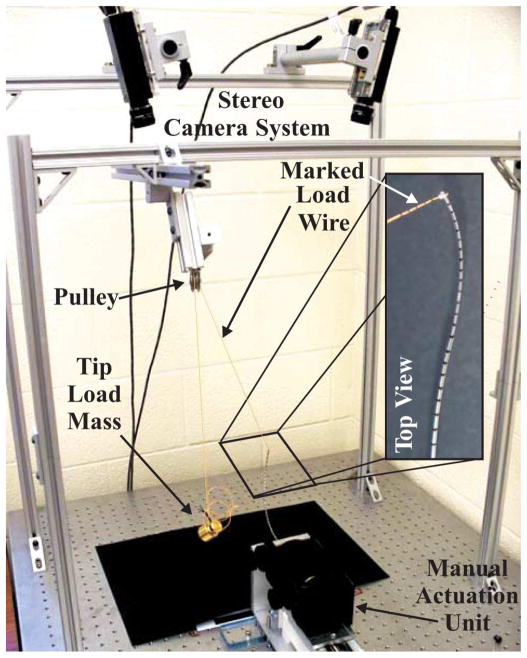
As shown in Fig. 8, at each of these configurations, a set of 3-D points along the backbone was determined via images taken from a calibrated pair of stereo cameras (Sony XCD-X710 Firewire cameras with a resolution of 1024 × 768 pixels) mounted above the robot. The fiducial markers shown in the inset image in Fig. 8 enabled determination of point correspondences for stereo triangulation after they had been identified in image coordinates by manually clicking on the center of the black bands in each image with MATLAB’s ginput command. The cameras were calibrated using a camera calibration tool-box for MATLAB [21], and the transformations between the stereo-camera coordinate frames and the robot base frame were initially estimated by triangulating a grid of points with known locations in the base frame and performing rigid point cloud registration [22]. The mean, max, min, and standard deviation of the euclidean registration errors were 0.57, 1.30, 0.11, and 0.32 mm, respectively. Directionally, the mean registration errors along the x-, y-, and z-axes were 0.50, 0.12, and 0.15 mm, respectively, where the x-axis points toward the cameras and the z-axis points along the robot axis at the base. These numbers encompass the error in the process of manually identifying the pixel coordinates of the points, as well as any error intrinsic to the stereo-camera system. We take this to be a rough estimate of the effective accuracy of our vision-based triangulation system.
Fig. 8.
Experimental setup. Tube bases were translated and rotated precisely by manual actuators. Three-dimensional backbone points were triangulated by identifying corresponding markers along the cannula in stereo images. The vector of the applied force was measured by triangulating positions along the wire that connects the cannula tip (via the pulley) to the applied weight.
In each of the 40 actuator configurations, a point force was also applied to the tip of the cannula by a wire tied through a hole in the tip of the inner tube, and backbone data were taken in the robot’s loaded state. The direction of the force vector applied by this wire was also determined by triangulating points marked along its length, as shown in Fig. 8. As can also be seen in the figure, the wire was run over a pulley and attached to a mass ranging from 100 to 500 g, as detailed in Table II. From the perspective of the cannula, the applied tip-load vector was in a different direction in each experiment because the robot was in a different configuration in each.
The pulley was mounted to a 6-degree-of-freedom (DOF) manually adjustable frame made from standard 80-20 Inc. parts. In each of the 40 robot configurations, before taking data, the location and angle of the pulley was adjusted as needed to make sure that the cable was orthogonal to the pulley axis. At this time, we also checked for hysteresis due to pulley friction by displacing the mass up and down (the flexible cannula acting as a spring) and noting that the pulley always returned to the same equilibrium angle when the weight was released. A subsequent experiment was carried out using this same procedure, in which the cable tension was measured using a six-axis load cell (Nano17, ATI, Inc.). The resolution of the cable tension was found to be ±0.009 N for the 0.981 N load, ±0.020 N for the 1.962 N load, and ±0.088 N for the 4.905 N load. Thus, we conclude that any unmodeled pulley effects did not significantly affect the loads transmitted to the cannula.
The two tubes have general precurvatures and . To obtain these, we began by capturing points along them (individually before inserting one into the other) using the stereo triangulation system in the manner described previously. We then fit a parametric polynomial curve to these points and gathered curvature data from these smooth fits. The components of precurvature for each tube are plotted in Fig. 5 (the tube curves were framed using Bishop’s frames; therefore, there are only x and y curvatures). Note that the curvatures are not constant over s, and all prior prototypes reported in the literature have had constant-curvature preset tube shapes.
B. Model Performance and Calibration
Since model error nearly always increases with the arc length along the robot toward the tip, we use tip location difference (called “tip error” henceforth) as a metric for comparing predictions to experiments, as has been done in many previous studies with active cannulas and other continuum robots. In our particular experiments, we also visually verified that the tip was the point of greatest deviation between model and experimental data by plotting the two together for all experimental positions.
Using the nominal parameter values (those that were directly measured or appeared on data sheets; for further discussion of active cannula nominal parameters, variances, and error propagation in model parameters, see [3]) listed in Table I, the mean tip error over all 80 experiments was 5.94 mm. Since actual values for the moduli of Nitinol tubes are highly uncertain (Young’s modulus is listed as 41–75 GPa on data sheets from the manufacturer, NDC, Inc.), the values of each tube’s bending and torsional stiffness were subsequently calibrated by finding the set of tube parameters that minimized the sum of the positional errors at three locations along the robot: the base (s = 0), the tip of the outer tube (s = l2 ), and the tip of inner tube (the tip of the device, s = l1 ). To reduce uncertainty in the registration of the robot base frame to the stereo-camera frames, we included small changes to the base-frame position (translations δx, δy, δz) and to the orientation (XYZ Euler angle rotations δα, δβ, δγ) as additional parameters to be calibrated. Our calibration process is accomplished by solving an unconstrained nonlinear optimization problem for the parameter set P = {E1 I1, E2 I2, J1 G1, J2 G2, δx, δy, δz, δα, δβ, δγ }:
where ek (s) = ||rm o del (s) – rdata (s)||k is the Euclidean distance between the model backbone prediction and the data in experiment k. To implement this minimization, we used the Nelder–Meade simplex algorithm, as implemented by MATLAB’s fminsearch function.
The parameters resulting from this model-fitting procedure are shown in comparison to their nominal counterparts in Table IV. The base-frame parameters showed only small changes during optimization, with XYZ Euler angles changing by −0.06°, 0.67°, and −0.58°, while the frame origin translated 2.0 mm. Using these calibrated parameters, the mean error over all experiments was 2.91 mm, as shown in Table VI.
TABLE IV.
Nominal and Calibrated Parameters
| Nominal Value | Calibrated Value | |
|---|---|---|
| E1I1 (Nm2) | 0.0204 | 0.0197 |
| J1G1 (Nm2) | 0.0157 | 0.0123 |
| E2I2 (Nm2) | 0.0458 | 0.0368 |
| J2G2 (Nm2) | 0.0352 | 0.0331 |
| δx (mm) | 0 | −1.7 |
| δy (mm) | 0 | −1.0 |
| δz (mm) | 0 | 0.3 |
| δα (deg) | 0 | −0.06 |
| δβ (deg) | 0 | 0.67 |
| δγ (deg) | 0 | −058 |
TABLE VI.
Tip Error Statistics—Calibrated Parameters
| Tip Error Statistic (mm) | 40 Unloaded Cases | 40 Loaded Cases | All Cases |
|---|---|---|---|
| mean | 2.89 | 2.92 | 2.91 |
| min | 0.62 | 0.91 | 0.62 |
| max | 8.49 | 15.20 | 15.20 |
| std. dev. | 2.19 | 2.52 | 2.34 |
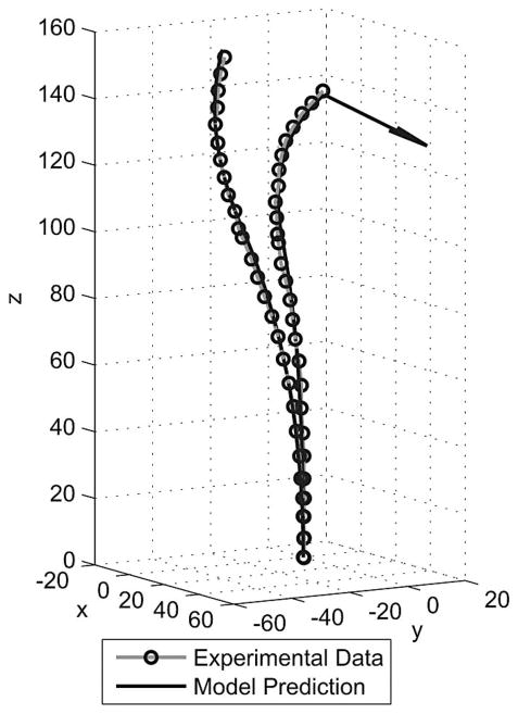
Fig. 9 shows the unloaded and loaded states of the cannula for actuator values of D1 = 154.7 mm, D2 = 30.7 mm, α1 = 135°, and α2 = 0°. Experimental data points are overlaid on the model prediction, and the model shown in the figure uses the calibrated parameters. The configuration shown is typical of all 80 experimental positions in that the tip error in both cases is about 3 mm, while the mean for all experiments is 2.91 mm. The rest of the shape is also typical of the 80 experimental runs in that the experimental data lie very close to the model prediction along the entire backbone, and the applied forces were sufficient to cause large deflection in all cases.
Fig. 9.
Comparison of model prediction and experimentally determined backbone points for the unloaded and loaded cases where actuators are set to D1 = 154.7 mm, D2 = 30.7 mm, α1 = 135°, and α2 = 0°. The direction of the 0.981 N applied force is shown by an arrow at the tip of the deformed model prediction. These examples are representative of our dataset—their tip errors (approximately 3 mm) are near the 2.91-mm mean tip error over all 80 experiments.
C. Distributed Load Experiment
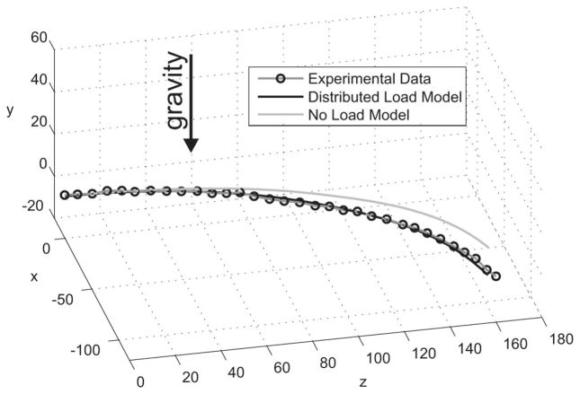
In order to demonstrate capability of the model of Section II to handle distributed loads, an experiment was conducted where a force distribution was applied along the length of the cannula. The actuator configuration was D1 = 122.7 mm, D2 = 30.7 mm, and α1 = α2 = 0°. Note that the cannula’s own weight is not sufficient to cause appreciable gravitational deflection. Therefore, we added additional weights along its length. As shown in Fig. 10, we approximated a distributed load by placing a large number of nuts along the shaft of the cannula (on both the outer tube and the portion of the inner tube which extended out from the outer tube). The nuts were spaced evenly along the shaft and had a total mass of 56.96 g. Stereo-point correspondences were determined based on manually clicking backbone points between the nuts. The tip of the device was covered by the last nut, thus making it impossible to locate the tip in stereo images; therefore, the tip was considered to be the last visualizable section of the backbone, and the model arc length was reduced by one nut width. The model and experimental data for this loading condition are shown in Fig. 11, along with the unloaded model for the same configuration. The tip error was 4.54 mm.
Fig. 10.
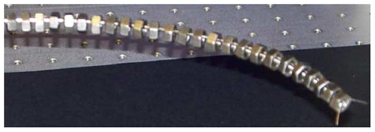
Active cannula under a distributed load represented by nuts equally spaced along its length.
Fig. 11.
Comparison of loaded and unloaded model predictions with experimentally determined backbone points for a distributed load. The tip error is 4.54 mm.
D. Statistical Analysis
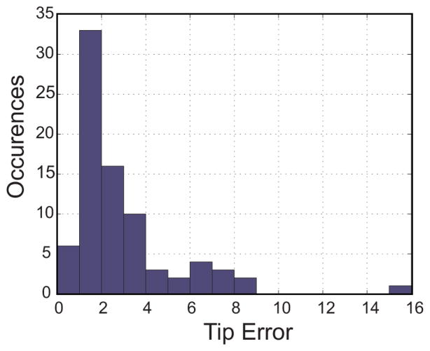
Error statistics for both nominal and fitted parameter sets are given in Tables V and VI. The dataset corresponds well to model predictions, with a mean tip error of 2.91 mm. An error histogram for all 80 cases shows that 75% of the errors were below 3 mm, and 85% were below 4 mm (see Fig. 12).
TABLE V.
Tip Error Statistics—Nominal Parameters
| Tip Error Statistic (mm) | 40 Unloaded Cases | 40 Loaded Cases | All Cases |
|---|---|---|---|
| mean | 3.76 | 7.82 | 5.79 |
| min | 0.60 | 2.42 | 0.60 |
| max | 10.59 | 25.53 | 25.53 |
| std. dev. | 2.85 | 4.13 | 4.08 |
Fig. 12.
Histogram of tip error for all 80 experiments using fitted model parameters. A total of 75% of the errors are below 3 mm, and 85% are below 4 mm.
A statistical outlier with 15.20 mm of tip error occurred in the loaded state with D1 = 130.7 mm, D2 = 30.7 mm, α1 = 270°, and α2 = 0°. The error in this case may have been increased by a procedural error (e.g., an incorrect α1 value being recorded) or simply a worst-case compounding of unmodeled phenomena and measurement uncertainty. It is also worth noting that in this configuration, the cannula was fully extended, and this error corresponds to only 7.68% of the arc length.
We note that for long, slender continuum robots, tip error is highly dependent on the total arc length, since errors tend to increase from the base of the cannula to its tip, as mentioned previously. The total arc length of the active cannula in our experiments ranged from 105.9 to 197.9 mm over the experimental dataset. Thus, an average tip error of 2.91 mm is approximately 1.5%–3% of the arc length.
E. Error Sources
The unmodeled phenomena of transverse shear strain and elongation could potentially be accounted for by allowing Δξ(s) to include the first three components, but the kinematic constraints in this case become more complex, and shear effects are known to be negligible for long, thin beams. Additional torsion due to friction is likely a more significant effect and could potentially be included in the model by additions to or modifications of (20), which describes the axial torque along a tube. Depending on cannula design (intratube tolerances, precurvature functions, arc lengths, etc.), we believe that friction can become more pronounced than it was in our experimental prototype, and future model extensions accounting for it may be useful, despite the minimal hysteresis observed in our experiments.
An unmodeled hardware detail that may be important is the fact that there is a small amount of clearance between the outside diameter of the inner tube and the inside diameter of the outer tube. This means that the tube tangents are not quite coincident where one exits the other, as the model assumes. In terms of design, this effect can be reduced by choosing tighter intratube tolerances at the cost of increasing frictional effects. Alternatively, this effect could be modeled by modifying the continuity of position and orientation across transition points to include a small rotational and translational displacement, where one tube exits another.
However, the fact that small tip errors were achieved without modeling any of the above effects indicates that they are largely negligible in our prototype. The model presented in this paper effectively captures the main structural features of concentric-tube continuum robots because it allows independent tube torsion during deformation. Whether it will be necessary to model any of these effects in the future will likely depend upon the design of the active cannula and the accuracy required by the application. Many clinical applications (e.g., needle biopsy or thermal ablation) can tolerate 3-mm tip errors. Other potential applications, such as retinal microsurgery, will require higher accuracy. In many cases, implementation of closed-loop control using this model is likely to significantly increase the operational accuracy and may render additional modeling detail unnecessary.
IV. Conclusion
In this paper, we have presented an extension of the geometrically exact Cosserat-rod theory to analyze a collection of concentric precurved tubes under a general set of distributed and point wrenches. We then tested this model in a set of experiments using an active-cannula robot composed of two Nitinol tubes with general preset curved shapes, subject to both tip loads and distributed loads along the length of the device. With parameter fitting, the model achieved an average tip error of 2.91 mm across all 80 experimental positions, which span the model-unique configuration space.
Our modeling work in this paper provides a theoretical foundation from which to understand active-cannula shape under load and from which to begin to explore many future applications. We expect that this model will be a valuable design tool in simulating proposed active-cannula designs, thereby enabling accurate compliance and kinematic analysis for cannulas intended to interact with tissue under environmental constraints. We also expect that it may facilitate use of the cannula’s flexibility to sense and control contact forces. Intrinsic-force sensing is desirable for thin continuum medical robots where inclusion of a force sensor could significantly affect device function [8]. Force information has the potential to enable tissue-property estimation to locate lesions via palpation or provide haptic feedback to the surgeon in a teleoperated system.
Acknowledgments
This work was supported in part by the National Science Foundation under Grant 0651803 and in part by the National Institutes of Health under Grant R44 CA13416.
This paper was presented at the 2010 IEEE International Conference on Robotics and Automation, Anchorage, AK.
Biographies
 D. Caleb Rucker (S’07) received the B.S. degree in engineering mechanics and mathematics from Lipscomb University, Nashville, TN, in 2006. He is currently working toward the Ph.D. degree in mechanical engineering with Vanderbilt University, Nashville.
In 2007, he was an Engineer with Jacobs Technology Group, Tullahoma, TN. His current research interests include medical robotics, continuum robotics, mechanics-based modeling, and control.
 Bryan A. Jones (S’00–M’00) received the B.S.E.E. and M.S. degrees in electrical engineering from Rice University, Houston, TX, in 1995 and 2002, respectively, and the Ph.D. degree in electrical engineering from Clemson University, Clemson, SC, in 2005.
He is currently an Assistant Professor with the Mississippi State University, Mississippi State, MS. From 1996 to 2000, he was a Hardware Design Engineer with Compaq, where he specialized in board layout for high-availability redundant array of independent disks (RAID) controllers. His current research interests include robotics, real-time control-system implementation, rapid prototyping for real-time systems, and modeling and analysis of mechatronic systems.
 Robert J. Webster, III (S’97–M’08) received the B.S. degree in electrical engineering from Clemson University, Clemson, SC, in 2002 and the M.S. and Ph.D. degrees in mechanical engineering from the Johns Hopkins University, Baltimore, MD, in 2004 and 2007, respectively.
In 2008, he joined the Faculty of Vanderbilt University, Nashville, TN, as an Assistant Professor of mechanical engineering, where he is currently the Director of the Medical & Electromechanical Design Laboratory. His current research interests include medical robotics, image-guided surgery, human–machine interfaces, and continuum robotics.
APPENDIX
Prior derivations of active-cannula shape have proceeded from both the perspective of energy minimization and Cosserat-rod theory. In this Appendix, we derive (20) using energy methods to demonstrate the consistency of the two approaches.
Using Euler’s linear constitutive bending equation (3), the elastic energy stored in the n-tube deformations is
Substituting (11) into this, we have
| (21) |
To find the functions θi, which minimize the stored elastic energy, we apply the following Euler–Lagrange equation to the functional n – 1 times, once with respect to each θi:
| (22) |
Note that the right-hand side is not zero, as is the case in prior free-space models [15]. Instead, we have which represents any generalized forces associated with θi. This corresponds to an arc-length-dependent torque per unit length applied about the e3 -axis of tube i. Applying (22) to the integrand of (21), we obtain
| (23) |
We can use (11) and (18) to replace u1 and u̇1 and then solve for u̇i,z to obtain (20).
Footnotes
Note that throughout the paper, we use the * to denote variables associated with undeformed individual tube shapes. Thus, r*(s) indicates the preset shape a single tube has in the absence of any other tubes or external loads.
Contributor Information
D. Caleb Rucker, Email: daniel.c.rucker@vanderbilt.edu, Vanderbilt University, Nashville, TN 37235, USA.
Bryan A. Jones, Email: bjones@ece.msstate.edu, Mississippi State University, Mississippi State, MS 39762, USA.
Robert J. Webster, III, Email: robert.webster@vanderbilt.edu, Vanderbilt University, Nashville, TN 37235, USA.
References
- 1.Rucker DC, Jones BA, Webster RJ., III A model for concentric tube continuum robots under applied wrenches. Proc IEEE Int Conf Robtics Autom. 2010:1047–1052. [Google Scholar]
- 2.Furusho J, Katsuragi T, Kikuchi T, Suzuki T, Tanaka H, Chiba Y, Horio H. Curved multi-tube systems for fetal blood sampling and treatments of organs like brain and breast. J Comput Assist Radiol Surg. 2006;1:223–226. [Google Scholar]
- 3.Webster RJ, III, Romano JM, Cowan N. Mechanics of precurved-tube continuum robots. IEEE Trans Robot. 2009 Feb;25(1):67–78. [Google Scholar]
- 4.Sears P, Dupont PE. A steerable needle technology using curved concentric tubes. Proc IEEE/RSJ Int Conf Intell Robots Syst. 2006:2850–2856. [Google Scholar]
- 5.Webster RJ, III, Okamura AM, Cowan NJ. Toward active cannulas: Miniature snake-like surgical robots. Proc IEEE/RSJ Int Conf Intell Robots Syst. 2006:2857–2863. [Google Scholar]
- 6.Rucker DC, Croom JM, Webster RJ., III Aiming surgical lasers with an active cannula. ASME J Med Devices. 2009;3:027506. [Google Scholar]
- 7.Trivedi D, Lotfi A, Rahn C. Geometrically exact models for soft robotic manipulators. IEEE Trans Robot. 2008 Aug;24(4):773–780. [Google Scholar]
- 8.Xu K, Simaan N. An investigation of the intrinsic force sensing capabilities of continuum robots. IEEE Trans Robot. 2008 Jun;24(3):576–587. [Google Scholar]
- 9.Li C, Rahn C. Design of continuous backbone, cable-driven robots. ASME J Mech Des. 2002;124(2):265–271. [Google Scholar]
- 10.Gravagne IA, Rahn C, Walker ID. Large-deflection dynamics and control for planar continuum robots. IEEE/ASME Trans Mechatron. 2003 Jun;8(2):299–307. [Google Scholar]
- 11.Camarillo DB, Milne CF, Carlson CR, Zinn MR, Salisbury JK. Mechanics modeling of tendon-driven continuum manipulators. IEEE Trans Robot. 2008 Dec;24(6):1262–1273. [Google Scholar]
- 12.Jones B, Gray R, Turlapati K. Three dimensional statics for continuum robotics. Proc IEEE/RSJ Int Conf Intell Robots Syst. 2009:2659–2664. [Google Scholar]
- 13.Rucker DC, Webster RJ, III, Chirikjian GS, Cowan NJ. Equilibrium conformations of concentric-tube continuum robots. Int J Robot Res. doi: 10.1177/0278364910367543. to be published. [Online]. Available: http://ijr.sagepub.com/content/early/2010/04/01/0278364910367543. [DOI] [PMC free article] [PubMed]
- 14.Dupont PE, Lock J, Itkowitz B, Butler E. Design and control of concentric-tube robots. IEEE Trans Robot. 2010 Apr;26(2):209–225. doi: 10.1109/TRO.2009.2035740. [DOI] [PMC free article] [PubMed] [Google Scholar]
- 15.Rucker DC, Webster RJ., III Parsimonious evaluation of concentric-tube continuum robot equilibrium conformation. IEEE Trans Biomed Eng. 2009 Sep;56(9):2308–2311. doi: 10.1109/TBME.2009.2025135. [DOI] [PubMed] [Google Scholar]
- 16.Antman SS. In: Nonlinear Problems of Elasticity. 2. Antman S, Marsden J, Sirovich L, editors. New York: Springer-Verlag; [Google Scholar]
- 17.Antman SS, Browne RC. Lecture Notes in Mathematics Series. Vol. 503. Berlin, Germany: Springer-Verlag; 1976. Applications of Methods of Functional Analysis to Problems in Mechanics: Local Invertibility Conditions for Geometrically Exact Nonlinear Rod and Shell Theorie. [Google Scholar]
- 18.Zadno G, Duerig T. Linear and non-linear superelasticity in NiTi. MRS Int Meet Adv Mater. 1989;9:201–209. [Google Scholar]
- 19.Murray RM, Li Z, Sastry SS. A Mathematical Introduction to Robotic Manipulation. Boca Raton, FL: CRC; 1994. [Google Scholar]
- 20.Kehrbaum S, Maddocks JH. Elastic rods, rigid bodies, quaternions and the last quadrature. Philos Trans: Math, Phys Eng Sci. 1997;355(1732):2117–2136. [Google Scholar]
- 21.Bouguet J-Y. Camera calibration toolbox for Matlab. 2010 Mar; [Online]. Available: http://www.vision.caltech.edu/bouguetj/calib_doc/index.html.
- 22.Arun KS, Huang TS, Blostein SD. Least-squares fitting of two 3-D point sets. IEEE Trans Pattern Anal Mach Intell. 1987 Sep;PAMI-9(5):698–700. doi: 10.1109/tpami.1987.4767965. [DOI] [PubMed] [Google Scholar]
- 23.Chirikjian S. Hyper-redundant manipulator dynamics: A continuum approximation. Adv Robot. 1995;9:217–243. [Google Scholar]


