Abstract
We describe a versatile method to enforce the rotation of subsets of atoms, e.g., a protein subunit, in molecular dynamics (MD) simulations. In particular, we introduce a “flexible axis” technique that allows realistic flexible adaptions of both the rotary subunit as well as the local rotation axis during the simulation. A variety of useful rotation potentials were implemented for the GROMACS 4.5 MD package. Application to the molecular motor F1-ATP synthase demonstrates the advantages of the flexible axis approach over the established fixed axis rotation technique.
1. Introduction
Biomolecular function often rests on or is performed through motions of subunits. Rotary motions, in particular, are essential for the function of many motor proteins. These nanomotors use the free energy of chemical reactions or ion concentration gradients to generate mechanical torque. Rotary mechanisms were unequivocally demonstrated for three molecular engines, the Fo and F1 motors in F-ATP synthase (F-ATPase)1,2 and the bacterial flagellar motor.(3) Recently, rotary motion was also shown for the V1 portion of the prokaryotic homologue of the vacuolar ATPase (V-ATPase).(4) Other motor proteins that are assumed to be rotary include DNA helicases(5) and proteins that translocate viral DNA into preformed capsids.6−8
The molecular mechanisms by which chemical reactions or transmembrane gradients drive protein rotary motions are in most cases not understood in full detail.(9) Also, these often quite complex motions are typically too slow or infrequent to be accessible to equilibrium molecular dynamics (MD) simulations. To overcome this limitation, techniques have been developed to exert external forces10−12 or torques13−15 to certain subunits to induce rotation and/or to increase its rate without severely perturbing the nature of the involved structural changes. This approach has also been used to simulate experiments in which biomolecules, such as proteins or DNA, are mechanically driven to rotate by externally applied torques by single molecule manipulation techniques.(16) In one impressive example, the F1 portion of ATP synthase (F1-ATPase) has been shown to produce ATP when the γ subunit is enforced to rotate using magnetic tweezers.(17)
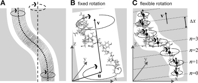
With exceptions,(18) in most simulations involving external torque, a fixed, “stiff” rotation axis has been used so far15,19,20 (dashed line in Figure 1A). As shown in the figure, this approach does not properly describe situations such as F1-ATPase, where the rotating part flexibly adapts (dotted lines) to the steric restraints set by the bearing (gray). To more realistically describe biomolecular rotations, we have therefore developed a flexible axis rotation technique that (i) exerts torque with a curved axis that flexibly fits the shape of an arbitrarily shaped cavity (Figure 1A), (ii) avoids any impact or bias previously introduced by the necessary choice of the pivot for the axis, (iii) perturbs the internal dynamics and flexibility of the rotated structure as little as possible, and (iv) allows the curvature of the axis to adapt to structural changes of the bearing. In summary, a rotated fragment such as the γ subunit inside the ATPase α3β3 stator should deform like a rotating pipe-cleaner.
Figure 1.
Comparison of fixed and flexible axis rotation. (A) Rotating the sketched shape inside the white tubular cavity creates severe artifacts when a conventional fixed rotation axis (dashed) is used. More realistically, the shape would revolve like a flexible pipe-cleaner (dotted) inside the bearing (gray). (B) Fixed rotation around an axis v with a pivot point specified by the vector u. (C) Subdividing the rotating fragment into slabs with separate rotation axes (↑) and pivot points (•) for each slab allows for the required flexibility. The distance between two slabs with indices n and n + 1 is Δx.
To clarify notation and to explain the basic ingredients needed for the flexible technique, we start with a recapitulation of the established fixed axis rotation, as implemented, e.g., in NAMD(21) or EGO.(22) From these notions, several more complex potentials will be developed and characterized, and the resulting forces will be derived. We will then motivate and describe in detail the flexible axis approach, for which we present two different variants. After outlining details of our GROMACS23,24 implementation, we will apply flexible axis rotation to the F1-ATPase molecular motor and test if our approach is indeed capable of providing more accurate torque or free energy profiles.
2. Fixed Axis Rotation
Stationary Axis with an Isotropic Potential
In the established fixed axis approach15,19−22 (Figure 1B), torque on a group of N atoms with positions xi (denoted “rotation group”) is applied by rotating a reference set of atomic positions—usually their initial positions yi0—at a constant angular velocity ω around an axis defined by a direction vector v̂ and a pivot point u. To that aim, each atom with position xi is attracted by a “virtual spring” potential to its moving reference position yi = Ω(t) (yi − u), where Ω(t) is a matrix that describes the rotation around the axis. In the simplest case, the “springs” are described by a harmonic potential
with optional mass-weighted prefactors wi = Nmi/M with total mass M = ∑i=1Nmi. The rotation matrix Ω(t) is
 |
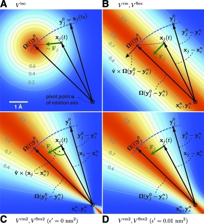
where vx, vy, and vz are the components of the normalized rotation vector v̂ and ξ := 1 − cos (ωt). As illustrated in Figure 2A for a single atom j, the rotation matrix Ω(t) operates on the initial reference positions yj0 = xj(t0) of atom j at t = t0. At a later time t, the reference position has rotated away from its initial place (along the blue dashed line), resulting in the force
which is directed toward the reference position.
Figure 2.
Selection of different rotation potentials discussed in the text and definition of notation. All four potentials V (color coded) are shown for a single atom at position xj(t). (A) Isotropic potential Viso, (B) radial motion potential Vrm and flexible potential Vflex, (C,D) radial motion 2 potential Vrm2 and flexible 2 potential Vflex2 for ε′ = 0 nm2 (C) and ε′ = 0.01 nm2 (D). The rotation axis is perpendicular to the plane and marked by ⊗. The light gray contours indicate Boltzmann factors e−V/(kBT) in the xj plane for T = 300 K and k = 200 kJ/(mol·nm2). The green arrow shows the direction of the force Fj acting on atom j; the blue dashed line indicates the motion of the reference position.
Pivot Free Isotropic Potential
We first address the bias introduced by an arbitrary choice of the pivot vector u. This arbitrariness is avoided by defining as the pivot the center of mass xc of the rotation group
which yields the “pivot-free” potential
with forces
Without mass-weighting, the pivot xc is the geometrical center of the group.
Parallel Motion Potential Variant
Obviously, the forces generated by the isotropic potentials (eqs 1 and 4) also contain components parallel to the rotation axis and thereby restrain motions along the axis of either the whole rotation group (in case of Viso) or within the rotation group (in case of Viso-pf). For cases where unrestrained motion along the axis is preferred, we have implemented a “parallel motion” variant by eliminating all components parallel to the rotation axis for the potential. This is achieved by projecting the distance vectors between reference and actual positions:
onto the plane perpendicular to the rotation vector
yielding
 |
and similarly
Pivot-Free Parallel Motion Potential
Replacing in eq 8 the fixed pivot u with the center of mass xc yields the pivot-free variant of the parallel motion potential. With
the respective potential and forces are
Radial Motion Potential
In the above variants, the minimum of the rotation potential is either a single point at the reference position yi (for the isotropic potentials) or a single line through yi parallel to the rotation axis (for the parallel motion potentials). As a result, radial forces restrict radial motions of the atoms. The two subsequent types of rotation potentials, Vrm and Vrm2, drastically reduce or even eliminate this effect. The first variant, Vrm (Figure 2B), eliminates all force components parallel to the vector connecting the reference atom and the rotation axis
with
This variant depends only on the distance pi·(xi−u) of atom i from the plane spanned by v̂ and Ω(t)(yi0−u). The resulting force is
Pivot-Free Radial Motion Potential
Proceeding similar to the pivot-free isotropic potential yields a pivot-free version of the above potential. With
the potential and force for the pivot free variant of the radial motion potential read
 |
Radial Motion 2 Alternative Potential
As seen in Figure 2B, the force resulting from Vrm still contains a small, second-order radial component. In most cases, this perturbation is tolerable; if not, the following alternative, Vrm2, fully eliminates the radial contribution to the force, as depicted in Figure 2C,
where a small parameter ε′ has been introduced to avoid singularities. For ε′ = 0 nm2, the equipotential planes are spanned by xi − u and v̂, yielding a force perpendicular to xi − u, thus not contracting or expanding structural parts that moved away from or toward the rotation axis.
We note that this variant is particularly suitable for free energy calculations via umbrella sampling techniques,(25) because the radial orientation of the equipotential planes shown in Figure 2C guarantees statistically consistent sampling of adjacent umbrella windows, as required for a consistent definition of the free energy profile via subspace projection. To see why this is actually the case, note that consistent umbrella sampling requires that for adjacent umbrella windows the “stack” of (3N − 1 dimensional) configurational subspaces defined by the values of the chosen reaction coordinate agrees, subspace by subspace, with the one defined by the values of the umbrella potential. This in turn requires that the equipotential planes shown in Figure 2 coincide with those of a rotated potential, which is obviously the case for Figure 2C, but not for Figure 2A or B.
Choosing a small positive ε′ (e.g., ε′ = 0.01 nm2, Figure 2D) in the denominator of eq 19 yields a well-defined potential and continuous forces also close to the rotation axis, which is not the case for ε′ = 0 nm2 (Figure 2C). With
the force on atom j reads
 |
Pivot-Free Radial Motion 2 Potential
The pivot free variant of the above potential is
with
the force on atom j reads
 |
3. Flexible Axis Rotation
As sketched in Figure 1A,B, the rigid body behavior of the fixed axis rotation scheme is a drawback for many applications. In particular, deformations of the rotation group are suppressed when the equilibrium atom positions directly depend on the reference positions. To avoid this limitation, eqs 18 and 24 will now be generalized toward a “flexible axis”, as sketched in Figure 1C. This will be achieved by subdividing the rotation group into a set of equidistant slabs perpendicular to the rotation vector, and by applying a separate rotation potential to each of these slabs. Figure 1C shows the midplanes of the slabs as dotted straight lines and the centers as thick black dots.
To avoid discontinuities in the potential and in the forces, we define “soft slabs” by weighing the contributions of each slab n to the total potential function Vflex by a Gaussian function
 |
centered at the midplane of the nth slab. Here, σ is the width of the Gaussian function, Δx the distance between adjacent slabs, and
A most convenient choice is σ = 0.7Δx and
 |
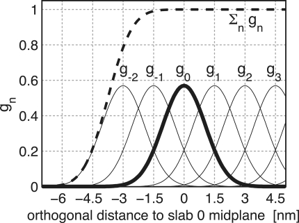
which yields a nearly constant sum, essentially independent of xi (dashed line in Figure 3), i.e.,
with |ε(xi)| < 1.3 × 10⁻⁴. This choice also implies that the individual contributions to the force from the slabs add up to unity such that no further normalization is required.
Figure 3.
Gaussian functions gn centered at nΔx for a slab distance Δx = 1.5 nm and n ≥ −2. Gaussian function g0 is highlighted in bold; the dashed line depicts the sum of the shown Gaussian functions.
To each slab center xcn, all atoms contribute by their Gaussian-weighted (optionally also mass-weighted) position vectors gn(xi)xi. The instantaneous slab centers xc are calculated from the current positions xi
 |
while the reference centers ycn are calculated from the reference positions yi
 |
Due to the rapid decay of gn, each slab will essentially involve contributions from atoms located within ∼3Δx from the slab center only.
Flexible Axis Potential
We consider two flexible axis variants. For the first variant, the slab segmentation procedure with Gaussian weighting is applied to the radial motion potential (eq 18/Figure 2B), yielding as the contribution of slab n
and a total potential function
Note that the global center of mass xc used in eq 18 is now replaced by xcn, the center of mass of the slab. With
the resulting force on atom j reads
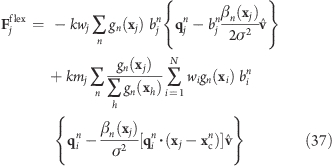 |
Note that for Vflex, as defined, the slabs are fixed in space and so are the reference centers ycn. If during the simulation the rotation group moves too far in the v direction, it may enter a region where—due to the lack of nearby reference positions—no reference slab centers are defined, rendering the potential evaluation impossible. We therefore have included a slightly modified version of this potential that avoids this problem by attaching the midplane of slab n = 0 to the center of mass of the rotation group, yielding slabs that move with the rotation group. This is achieved by subtracting the center of mass xc of the group from the positions
such that
 |
To simplify the force derivation, and for efficiency reasons, we here assume xc to be constant, and thus ∂xc/∂x = ∂xc/∂y = ∂xc/∂z = 0. The resulting force error is small (on the order of O(1/N) or O(mj/M) if mass-weighting is applied) and can therefore be tolerated. With this assumption, the forces Fflex-t have the same form as eq 37.
Flexible Axis 2 Alternative Potential
In our second variant, slab segmentation is applied to Vrm2 (eq 24), resulting in a flexible axis potential without radial force contributions (Figure 2C)
 |
with
 |
 |
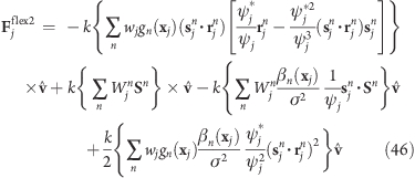
the force on atom j reads
 |
Applying transformation 38 yields a translation-tolerant version of the flexible 2 potential, Vflex2-t. Again, assuming that ∂xc/∂x, ∂xc/∂y, and ∂xc/∂z are small, the resulting equations for Vflex2-t and Fflex2-t are similar to those of Vflex2 and Fflex2.
4. GROMACS Implementation
For an efficient implementation, the following issues were taken into account. GROMACS 4 distributes the atoms among the parallel processors by domain-decomposing(24) the simulation box and assigning each domain to a processor. Depending on van der Waals and Coulomb cutoff settings, positions of atoms near the domain boundaries are communicated such that each processor can compute the forces assigned to its domain. However, the calculation of some of the proposed potentials and forces requires atom positions not present on the local processor. For instance, the pivot free potentials require the center of mass of the rotation group, while the flexible potentials require all N positions of the rotation group. The required coordinates are therefore distributed to all processors before the force calculations, which entails one extra communication step in the rotation module. Further, repeated expressions such as the last terms in eqs 18 and 28 are precalculated whenever possible. For the efficient computation of the forces Fflex, the inner sum of the last term of eq 37
 |
is rewritten as
such that the repeated terms
are also precomputed for each relevant slab n and then used for the calculation of each Fj term. Likewise, for Fflex2, the terms Sn (eq 45) of eq 46 are precalculated.
Moreover, for the flexible potentials, only significant contributions to V and F are computed, defined by a cutoff value of gn(x) ≥ gnmin with a default value gn = 0.001, which is checked according to a simple distance criterion. Also, the atoms of the rotation group are sorted according to their position along the rotation vector such that for each slab n, a first and a last index i between gn(xi) ≥ gnmin ∀i ∈ [ifirst...ilast] is stored, and all contributions outside that range can safely be ignored.
Special care has been taken for periodic boundary conditions. Here, the appropriate periodic image for each of the particles of the rotation group has to be chosen such that groups are not split. For fixed axis rotation, each atom is put closest to its current reference position. For the flexible and pivot-free radial motion potentials, each atom is put next to its position at the previous time step, thereby ensuring the integrity of all rotation fragments.
5. Application to F1-ATP Synthase
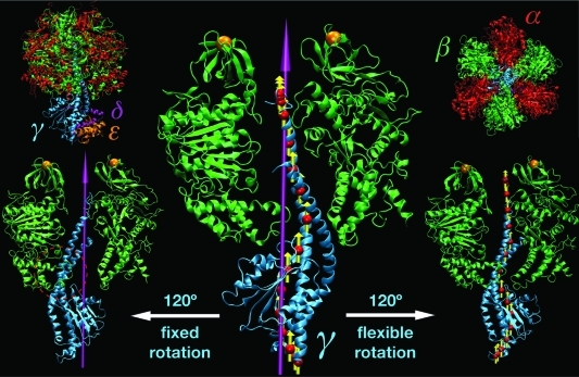
As a sample application of our flexible axis approach, and to compare results obtained by fixed and flexible axis rotation, a series of all-atom MD simulations was performed in which the γ subunit of F1-ATPase was enforced to rotate with respect to its stator part, α3β3 (Figure 4).
Figure 4.
F1-ATPase structure. In the upper left (right) corners, the full protein structure (α3β3δε) is shown in a side (top) view. Subunit color-coding is α, red; β, green; γ, cyan; δ, magenta; and ε, orange. The central panel illustrates the initial orientation of the rotor domain (γδε) with respect to the stator (α3β3); for the sake of simplicity, only the γ and two β subunits are shown. The 3-fold symmetry axis of α3β3 that was used as a rotation axis in Viso is shown in magenta. The red spheres and yellow arrows depict slab centers and local rotation axes as used by the flexible potentials. The left and right side panels show the orientation of the rotor after 120° of enforced rotation using Viso and Vflex2, respectively. The two orange spheres denote harmonic restraints applied to the N-terminal tags of the β subunits. This is to prevent co-rotation of the α3β3 stator in close resemblance to single-molecule force probe experiments, in which the stator is immobilized by attaching the protein to the surface via His tags attached to one subunit type (usually the β chains). Figure prepared with VMD.(38)
F1-ATPase is the soluble domain of the FoF1-ATP synthase, a rotary motor protein that synthesizes ATP from ADP using the electrochemical proton gradient across the membrane as its energy source.(26) The mitochondrial F1-ATPase is an oligomeric protein consisting of nine polypeptide chains, α3β3γδε.(27) In synthesis direction, F1-ATPase is driven by the membrane-embedded proton-translocating Fo motor while the F1 mobile subunit, γδε, rotates clockwise (seen from the membrane) within the bearing formed by the hexagonally arranged α and β chains.28,26 The energy transmitted mechanically via the rotating subunit is subsequently used at the catalytic sites of α3β3 for ATP synthesis. To prevent co-rotation, the α3β3 hexamer is connected to the membrane-embedded Fo motor by a peripheral linker stalk. Despite numerous theoretical29−31 and simulation studies,15,32−36 the molecular mechanism of energy transmission between the rotor subunit and the ligand binding sites in the stator is still not fully understood.(37)
Simulation Setup
The initial configuration of the F1 motor was based on the X-ray structure of bovine F1-ATPase determined at 2.4 Å resolution(39) (Protein Data Bank entry 1E79). The covalently bound inhibitor as well as the glycerol and sulfate molecules were removed, leaving only Mg·ATP and Mg·ADP ligands in their respective binding sites. All crystal water molecules were retained. Two five-residue-long loops missing from the γ subunit were modeled with tCONCOORD.(40) Protonation states of ionizable groups were set according to the pKa shifts calculated with the DelPhi(41) interface of WhatIf.(42) The protein structure was solvated with 87 321 water molecules in a 16.7 × 13.8 × 13.8 nm rectangular unit cell. To neutralize the system and to obtain physiological ionic strength, 261 Na+ and 216 Cl− ions were added. The system was energy-minimized using the steepest descent method in two stages. First, all heavy atoms of the protein and the protein’s ligands were kept fixed; subsequently, all atoms in the system were allowed to relax.
All simulations were performed with GROMACS 4.0(24) in which the potentials Viso, Vflex, and Vflex2 were implemented. For convenience, we here also describe the newer 4.5 version, which produces the same results for the Viso, Vflex, and Vflex2 potentials but includes nine additional rotation potentials.
For the protein as well as its ligands and ions, the OPLS/AA force field43,44 was used, and TIP4P(45) was used for the water. All production runs were carried out in the NPT ensemble at 300 K and 1 bar. Temperature and pressure were controlled by Nosé−Hoover46,47 (coupling constant τt = 0.5 ps) and Parrinello−Rahman48,49 (τp = 2.0 ps) schemes, respectively. To avoid severe density oscillations, the first 5 ns of the NPT equilibration run were performed with Berendsen weak coupling(50) for temperature and pressure. Periodic boundary conditions were applied in 3D, and electrostatic forces were calculated with the particle mesh Ewald (PME) method51,52 using a real-space cutoff of 1 nm and an FFT grid density of 10 nm−1. Lennard-Jones interactions were truncated at 1 nm. Covalent bond lengths in the protein and ligand were constrained to their reference values with P-LINCS.(53) SETTLE was used to constrain the water geometry.(54) Equations of motion were integrated using the leapfrog scheme with a time step of 2 fs. Prior to enforcing the rotor movement, the system was equilibrated for 10 ns at the target temperature and pressure. During the first 1 ns of this run, all protein heavy atoms were harmonically restrained to their initial positions.
To mimic the effect exerted on the F1 subunit by the rotation of the Fo motor, a potential of the form Viso (eq 1), Vflex (34), or Vflex2 (40) was applied during the production runs. All 272 Cα atoms of the γ subunit were chosen as a rotation group. The longest principal axis of the α3β3 stator, i.e., the eigenvector of the inertia tensor of α3β3 corresponding to the largest eigenvalue, was used as a rotation vector v. For the fixed variant, the pivot vector u of the axis was placed at the center of mass of the α3β3 units, thus defining the 3-fold pseudosymmetry axis of the stator subunit (Figure 4). For the flexible axis runs, a slab distance of Δx = 1 nm, a Gaussian function cutoff of gnmin = 0.001, and ε′ = 0 nm2 were chosen. The γ reference positions were rotated counter-clockwise around v at an angular rate of ω = 0.021°/ps over 6 ns of the simulation time, yielding a 120° rotation of the γδε domain. Due to its symmetry, this covers a complete synthesis cycle, as also seen from the observed stepped motion of the γδε domain.(28) To examine the effect of the chosen spring constant k, for each of the three potentials, five runs were performed with k values ranging from 100 to 800 kJ/(mol·nm2). In each case, all heavy atoms of the N-terminal six-residue sequences of each β subunit were harmonically restrained to their initial positions using a force constant of 1500 kJ/(mol·nm2). Additionally, for k = 600 kJ/(mol·nm2), a complete 360° rotation of the γδε domain was simulated.
Performance
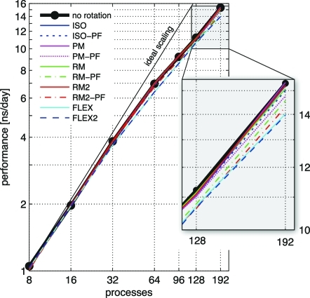
We demonstrate that, due to the optimizations described in the implementation section, simulation performance is nearly unaffected for typical setups such as the F1-ATPse system, where only a small fraction of all atoms are subjected to a rotation potential. The described ATPase example with the implemented rotation types was benchmarked (Figure 5) on a cluster of Intel Xeon L5430 nodes connected by a DDR Infiniband network. Each node comprised eight processor cores running at 2.66 GHz. An Intel MPI 3.2.1 was used with the Intel 11.1 compiler and the FFTW 3.2 library. For the benchmarks, Coulomb and van der Waals cutoffs were set to 0.9 nm and the Fourier grid to 144 × 120 × 120 points, yielding a grid spacing of less than 0.12 nm in each dimension. Separation into long-range (PME-only) and short-range (particle−particle) processes was allowed. The optimal number of PME-only processes was derived with the g_tune_pme(55) tool using 2000 equilibration steps for the dynamic load balancing, with run times taken from 2000 subsequent steps.
Figure 5.
GROMACS 4.5 performance for various rotation potentials (colors) compared to a simulation without rotation. The system comprises 401 152 atoms in total, of which 2116 are subjected to the rotation potential. For the flexible potentials, slab distance Δx = 1 nm and gnmin = 0.001 have been chosen. The thin black line denotes ideal scaling.
With the N = 272 Cα atoms of the γ subunit as the rotation group, none of the potentials significantly reduced the MD performance. To be able to analyze the scaling behavior (Figure 5), the rotation group was therefore enlarged to contain all N = 2116 atoms of the γ subunit. As seen, the overall performance decreases only slightly compared to the case without rotation. For the most computationally demanding flexible potentials, on eight processors, a 2% decrease is seen and a 9% decrease on 192 processors.
6. Results
Evolution of the Rotor Angle
To verify that the proposed methods properly control the motion of the rotary subunit, we first determined the time evolution of the rotor angle θ. The actual rotation angle θ(t) of the γ subunit was determined by a mass-weighted root-mean-square deviation (RMSD) fit to the initial (θ = 0°) configuration of the γ backbone. Figure 6 shows θ(t) with respect to the α3β3 symmetry axis.
Figure 6.
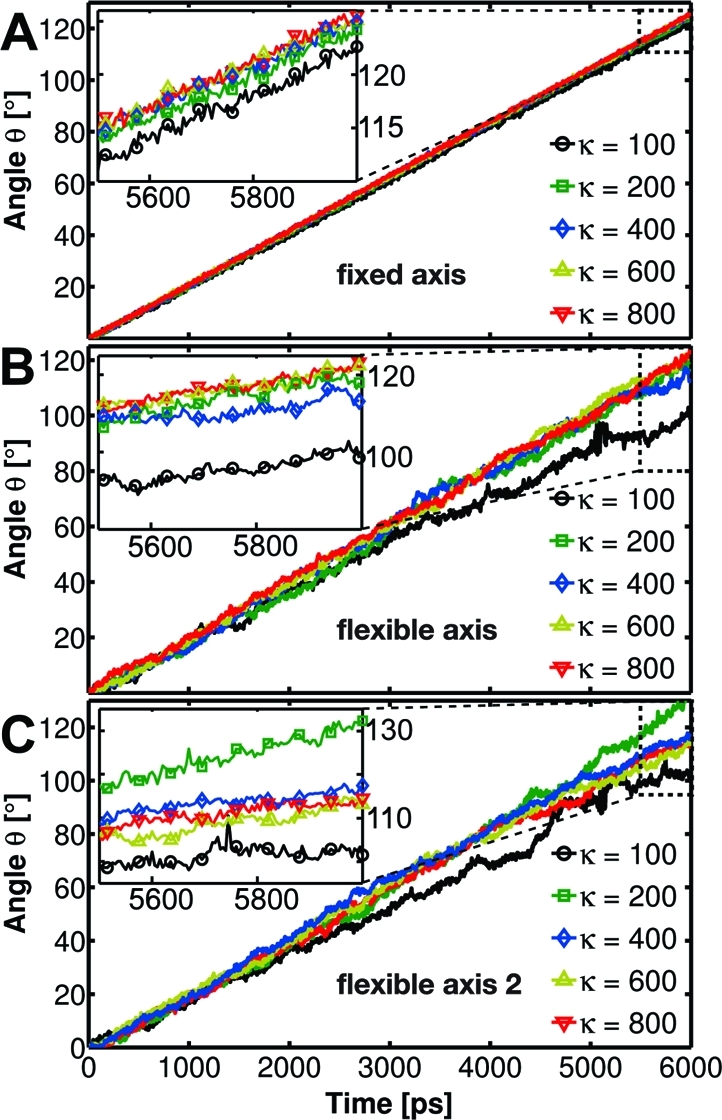
Time evolution of the γ rotor angle with respect to the α3β3 symmetry axis for the F1-ATPase motor enforced to rotate in the synthesis direction using the potentials Viso (A), Vflex (B), and Vflex2 (C) with spring constants k of 100−800 kJ/(mol·nm2).
The results show that in all 6-ns-long enforced rotation runs the rotor changes its orientation with respect to the stator by the expected 120°. The angle increases nearly linearly with time, with the slope reflecting the constant angular velocity of 0.021°/ps, at which the reference is rotated. For fixed axis rotation, the subunit closely follows the reference for all tested force constants k = 100−800 kJ/(mol·nm2). In contrast, for both flexible variants, a less regular evolution is observed, as indicated by the large fluctuations of θ for k = 100 kJ/(mol·nm2). These result from conformational changes of the rotor that occur because the flexible method allows for structural relaxations and adaptations to the bearing. Additionally, at high rotation velocities, frictional forces occur, which cause further conformational changes.
Movies illustrating the effect of the fixed and flexible axis methods have been included within the Supporting Information. In the movies, a Viso and a Vflex2 rotation potential with k = 600 kJ/(mol·nm2) is applied to all Cα atoms of the γ subunit.
For a quantitative comparison of the γ subunit internal deformation, Figure 7 shows the time evolution of the RMSD of the γ backbone atoms from their initial configuration. Relatively small RMSD variations are observed for the fixed method, confirming nearly rigid-body like rotation. In contrast, both flexible axis methods allow for structural rearrangements particularly for small k values. A secondary structure analysis shows that for the F1-ATPase flexibly rotating at 0.021°/ps the force constant k should be 200 kJ/(mol·nm2) or larger to preserve the rotor coiled-coil conformation of the crystal structure (Figure 4). For any of the rotation potentials, the force constant will depend on the studied system and on the rotation rate. Generally, higher rotation rates will require larger force constants that stabilize the rotation group with the help of a stronger coupling to its reference. Yet, the decrease in conformational freedom with increasing k (Figure 7) shows that when using the flexible axis approach one can optimize the tradeoff between structural flexibility and mechanical resistance of the rotary subunit. Note that the 120° rotations, in principle, cannot perfectly reproduce the starting configuration of the F1-ATPase, as in our simulations the rotor motion is not accompanied by occupancy changes of the active sites.
Figure 7.
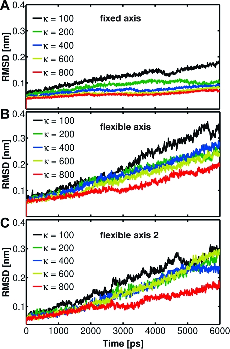
RMSD of the γ subunit backbone atoms with respect to the X-ray structure as a function of time for the F1 motor driven to rotate in the synthesis direction using the potentials Viso (A), Vflex (B), and Vflex2 (C) with spring constants k of 100−800 kJ/(mol·nm2).
Because for the flexible potentials the local rotation axis adapts dynamically, it is interesting to monitor the evolution of the F1 rotor angle θ also with respect to a variable axis. Figure 8 shows the time dependence of θ computed in the same manner as previously but now with the instantaneous (longest) principal axis of the γ subunit used as the reference axis. Significantly smoother variation of θ with time is seen in Figure 8 compared to using a fixed symmetry axis (Figure 6B,C). This result illustrates the ability of the flexible methods to adapt the rotation geometry to the structure and conformational changes of the stator.
Figure 8.
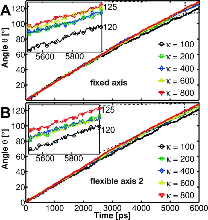
Time evolution of the angular position of the γ rotor computed as the best-fit angle with respect to the γ longest principal axis for the F1 motor enforced to rotate in the synthesis direction using Viso (A) and Vflex2 (B).
Torque Profiles
We will now characterize the different rotation methods in terms of torque and energetics. Because the efficiency of the chemomechanical energy transmission in the F1-ATPase, when studied in single molecule measurements, is close to 100%,(28) and due to the implied tight coupling between the mechanical reaction coordinate (e. g., the θ angle) and conformational changes in the catalytic subunit, the work necessary to enforce a 120° rotation of F1-ATPase in the synthesis direction should approach the free energy of ∼50−70 kJ/mol required for ATP synthesis.26,37
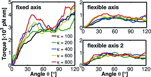
Figure 9 therefore compares the torque profiles along the mechanical reaction coordinate θ (eq 53) for the three methods considered above. As can be seen, for both flexible axis potentials, the average torque along θ is about 5 times smaller than that for the fixed axis potential. Assuming that for infinitely slow rotation the (equilibrium) torque curve is smaller than the observed torques, and, further, that this difference is due to dissipation or other nonequilibrium effects, this result implies that the flexible axis approach reduces the dissipated energy by at least a factor of 5 with respect to the fixed axis potential.
Figure 9.
The angular dependence of the driving torque for the γ subunit enforced to rotate in the synthesis direction using Viso (fixed axis), Vflex2 (flexible axis), and Vflex2 (flexible axis 2), using five different spring constants k = 100−800 kJ/(mol·nm2). All torque profiles were smoothed using a running average window of 8°.
Integrated over 120°, the corresponding work is 5900 ± 300, 1400 ± 100, and 1490 ± 80 kJ/mol, for the fixed, flexible, and flexible 2 potential, respectively. Due to the large angular velocity applied as well as the resulting nonequilibrium nature of this process, this work is still much larger than the free energy of ATP synthesis but clearly shows the dramatic reduction by the flexible axis method. For much lower velocities of 0.00042°/ps, the integrated work reduces further to 350 ± 50 kJ/mol (data not shown).
Already for the short simulations, the dependence of the torque on the angular position of the rotor reveals details of the free energy landscape governing the F1 rotation. In all simulations with a flexible axis potential (Figures 9 and 10), only small variations of the average torque with respect to the rotor angle are observed. This suggests that the underlying energy landscape is smooth and nearly linear, which is in agreement with recent experiments.26,56 However, due to the much larger angular velocity employed here, the torque values calculated from our simulations are at least one order of magnitude larger than the F1-generated torque measured under a viscous load (40−50 pN·nm).28,56 In addition, the calculated torque profiles indicate that the free energy landscape is steepest at θ ≈ 40°. The increase of the torque for θ > 90° that shows up in the fixed type points to shortcomings of this particular method, which will be discussed in the next section.
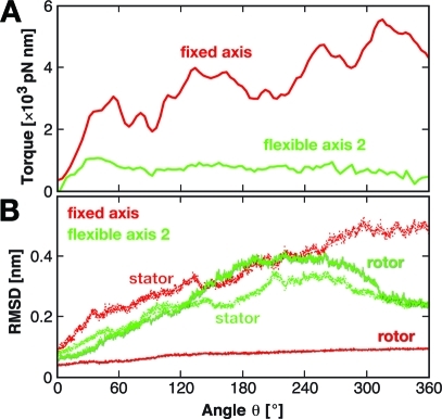
Figure 10.
Evolution of the driving torque for the γ subunit enforced to rotate in the synthesis direction using Viso (red) and Vflex2 (green) with k = 600 kJ/(mol·nm2) (A). RMSD of the γ rotor backbone atoms (solid) and of the α3β3 stator backbone atoms (dotted) with respect to their respective X-ray structure (B).
Since in the simulations the motion along the mechanical reaction coordinate is not synchronized with changes in chemical occupancy of the stator binding sites, we do not expect the torque to drop to zero after 120° of rotation. To examine how far our nonequilibrium simulations are from the reversible limit, Figure 10A shows torque profiles of full 360° rotations applying Viso and Vflex2 with k = 600 kJ/(mol·nm2). As can be seen, the torque determined for the fixed axis case increases strongly, whereas for the flexible case, after a small increase up to θ ≈ 40°, the torques decrease toward considerably smaller values. This result underscores that the flexible potential perturbs the system to a much lesser extent, such that it remains much closer to equilibrium than for a fixed axis rotation.
The fixed axis potential induces structural changes almost exclusively in the bearing (stator in Figure 10B) while in the flexible axis case, the structural changes are distributed rather equally among the rotating subunit and its bearing. Moreover, in the flexible axis case, both structures nearly approach the starting structure (θ = 0°) at the end of a whole 360° turn with an RMSD below 2.5 Å, which is not seen for the fixed axis simulation.
Origin of Differences in Energetics of Fixed and Flexible Axis Rotation
When using a simple fixed axis rotation potential, the rotating part behaves like a rigid body. In combination with the fixed axis, this behavior can cause unphysical close contacts and strong torques between the rotor and the bearing, which may cause extensive artificial structural changes of the bearing. The flexible axis approach, in contrast, keeps the system closer to the equilibrium for two reasons. First, the self-adjusting local rotation axis ensures an overall optimal position of the pivot; second, the built-in flexibility allows for structural relaxation of the rotating part and thus locally minimizes sterical hindrances. As the F1-ATPase motor components are strongly coupled and leave only little room for the rotating subunit inside the bearing, both reasons allow for the necessary tight adaption of the γ rotor to the α3β3 bearing.
To quantify this effect, Figure 11 displays the enforced conformational changes of the bearing, in terms of stator RMSD with respect to its X-ray structure as a function of time for the α2 subunit. This subunit was chosen because it interacts most closely with the γ rotor throughout the whole runs. It is evident that the structural changes induced in α2 are considerably larger for fixed axis rotation than for the flexible potentials. Secondary structure analysis reveals that in the former case the structural motifs exposed to the center of the α3β3 hexamer are distorted by the rotating γ subunit. Also in Figure 4 one can notice partial disruption of the helices in the C-terminal part of the β3 subunit (the bottom part of β on the left side of γ, red dashed circle) when it is pressed upon by the rotor driven to rotate around the fixed axis. The torque increase for angles θ > 90° (Figure 9, left, and Figure 10) reflects this effect, which is mainly due to wrapping of the β3 C-terminal domain around the γ subunit.
Figure 11.
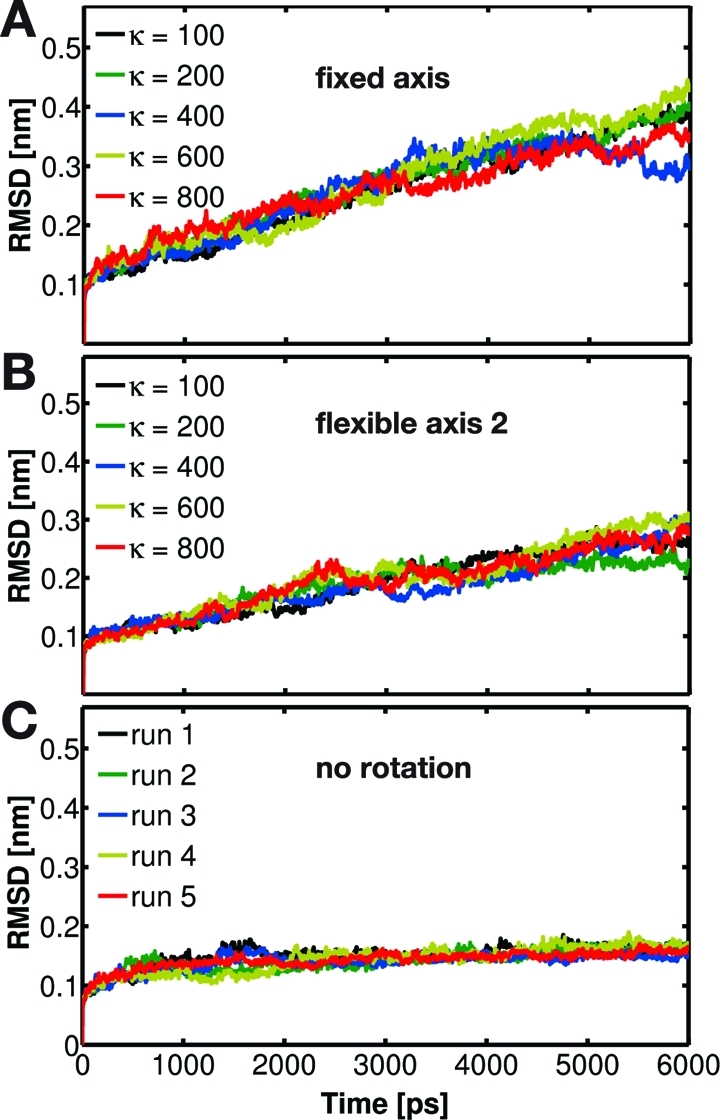
RMSD of the α3 subunit backbone atoms with respect to the X-ray structure when driving γ subunit rotation using Viso (A) and Vflex2 (B). For comparison, the corresponding RMSD evolution for five independent free MD runs is also shown (C).
7. Conclusions
We have developed, implemented, and tested a new method to enforce the rotation of protein subunits that allows for (i) a flexible rotation axis and (ii) structural adaptions of the rotated subunit to its environment. For γ subunit rotation in F1-ATPase, we have shown that our flexible axis method reduced the frictional dissipation of the γ subunit within the α3β3 bearing by more than a factor of 5. As a result, also the induced torque was 5-fold smaller compared to the one using a fixed axis.
Concerning the use of the flexible axis potentials developed here, we should like to point out two possible caveats. The first caveat is due to the fact that, while the pivot vector is free to adapt flexibly, the orientation of the direction vector is fixed. For systems where the subsystem subjected to the rotation potential is embedded within a curved “bearing”, the flexible adaptation will work properly only as long as the angle between the orientations of the bearing axis and the direction vector is not too large, i.e., for not too strong bending of the bearing. In extreme cases such as a complete U-shaped bearing, artificial structural changes of the bearing similar to those induced by fixed axes may occur. This problem can be addressed by subdividing the system into several parts and using a separate flexible rotation axis for each of these parts, with orientation vectors locally adapted to the respective part of the bearing.
The second caveat regards the proper choice of the slab thickness. If chosen too small, only a few atoms will be assigned to each slab, thus compromising the averaging that defines the pivot vector of each slab. In contrast, if chosen too large, the slabs might stretch over regions that would require changing pivot vectors, in which case the enforced rotation would induce, albeit to a lesser extent, the artifacts caused by fixed axis approaches. Obviously, in the limit of just a single slab covering the complete rotating subsystem, the fixed axis potential is recovered.
With these limitations and caveats in mind, our flexible axis potentials are applicable to a broad range of quite diverse biomolecular systems, processes, and functions. Apart from mimicking molecular rotary motors, it can also serve to restrain the orientation of a protein or ligand, or, in combination with umbrella sampling, to calculate the preferred orientation of transmembrane proteins or membrane-active agents within a lipid bilayer. Further, the method is expected to yield more accurate free energy profiles along circular reaction coordinates via umbrella sampling. In the long run, our flexible axis approach might prove useful for the study and design of synthetic nanodevices with rotating elements, such as those considered for molecular nanotechnology.(57)
Acknowledgments
This work has been supported by the EU (NANOMOT/NEST 029084) and the Deutsche Forschungsgemeinschaft (DFG GR 1590/2-1). We thank Anna Neumann for the derivation of eqs 23 and 46, and Marcus Kubitzki and Berk Hess for helpful discussions.
Appendix: Using GROMACS for Enforced Rotation Simulations
All methods and potentials described in this paper have been implemented into GROMACS and will be part of the next major release. For immediate use, the rotation repository branch should be checked out from the GROMACS git repository. See www.gromacs.org for how to access the repository.
To use one of these potentials, the particles i that are to be subjected to rotation potentials are defined via index groups rot_group0, rot_group1, etc., in the grompp preprocessor mdp input file. The reference positions yi0 are read from a file provided to grompp. If no such file is found, xi(t = 0) are used as reference positions and written to file such that they can be used for subsequent setups. All parameters of the potentials such as k, ε′, etc. (Table 1) are provided via input file parameters; rot_type selects the type of the potential. The option rot_massw allows one to choose whether or not to use mass-weighted averaging. Table 2 summarizes observables that are written to additional output files, which are described below.
Table 1. Parameters Used by the Various Rotation Potentials Defined Abovea.
| parameter | k | v̂ | u | ω | ε′ | Δx | gnmin | ||
|---|---|---|---|---|---|---|---|---|---|
| grompp input | k | vec | pivot | rate | eps | slab_dist | min_gauss | ||
| unit | variable name | eq | [(kJ)/(mol·nm2)] | [-] | [nm] | [deg/ps] | [nm2] | [nm] | [-] |
| fixed axis: | |||||||||
| isotropic | Viso | 1 | X | X | X | X | - | - | - |
| −pivot-free | Viso-pf | 4 | X | X | - | X | - | - | - |
| parallel motion | Vpm | 8 | X | X | X | X | - | - | - |
| −pivot-free | Vpm-pf | 12 | X | X | - | X | - | - | - |
| radial motion | Vrm | 13 | X | X | X | X | - | - | - |
| −pivot-free | Vrm-pf | 18 | X | X | - | X | - | - | - |
| radial motion2 | Vrm2 | 19 | X | X | X | X | X | - | - |
| −pivot-free | Vrm2-pf | 24 | X | X | - | X | X | - | - |
| flexible axis: | |||||||||
| flexible | Vflex | 34 | X | X | - | X | - | X | X |
| −transl. tol. | Vflex-t | 39 | X | X | - | X | - | X | X |
| flexible2 | Vflex2 | 40 | X | X | - | X | X | X | X |
| −transl. tol. | Vflex2-t | X | X | - | X | X | X | X | |
X’s indicate which parameter is actually used.
Table 2. Quantities Recorded in Output Files during Enforced Rotation.
| quantity | unit | equation | output file | fixed | flexible | controlled by |
|---|---|---|---|---|---|---|
| V(t) | kJ/mol | see Table 1 | rotation | X | X | nstrout |
| θref(t) | deg | θref(t) = ωt | rotation | X | X | nstrout |
| θav(t) | deg | 50 | rotation | X | - | nstrout |
| θfit(t), θfit(t,n) | deg | 52 | rotangles | - | X | nstsout |
| y0(n), x0(t,n) | nm | 32, 33 | rotslabs | - | X | nstsout |
| τ(t) | kJ/mol | 53 | rotation | X | - | nstrout |
| τ(t,n) | kJ/mol | 53 | rottorque | - | X | nstsout |
Angle of Rotation Groups: Fixed Axis
For fixed axis rotation, the average angle θav(t) of the group relative to the reference group is determined via the distance-weighted angular deviation of all rotation group atoms from their reference positions
 |
Here, ri is the distance of the reference position to the rotation axis, and the difference angles θi are determined from the atomic positions, projected onto a plane perpendicular to the rotation axis through pivot point u (see eq 7 for the definition of ⊥)
The sign of θav is chosen such that θav > 0 if the actual structure rotates ahead of the reference.
Angle of Rotation Groups: Flexible Axis
For flexible axis rotation, two outputs are provided, the angle of the entire rotation group and separate angles for the segments in the slabs. The angle of the entire rotation group is determined by an RMSD fit of xi to the reference positions yi0 at t = 0, yielding θfit as the angle by which the reference has to be rotated around v̂ for the optimal fit
To determine the local angle for each slab n, both reference and actual positions are weighted with the Gaussian function of slab n, and θfit(t,n) is calculated as in eq 52 from the Gaussian-weighted positions.
For all angles, the input option rot_fit_method controls whether a normal RMSD fit is performed or whether for the fit each position xi is put at the same distance to the rotation axis as its reference counterpart yi0. In the latter case, the RMSD measures only angular differences, not radial ones.
Angle Determination by Searching the Energy Minimum
Alternatively, for rot_fit_method=potential, the angle of the rotation group is determined as the angle for which the rotation potential energy is minimal. Therefore, the used rotation potential is additionally evaluated for a set of angles around the current reference angle. In this case, the rotangles.log output file contains the values of the rotation potential at the chosen set of angles, while rotation.xvg lists the angle with minimal potential energy.
Torque
The torque τ(t) exerted by the rotation potential is calculated for fixed axis rotation via
where ri(t) is the distance vector from the rotation axis to xi(t) and fi⊥(t) is the force component perpendicular to ri(t) and v̂. For flexible axis rotation, torques τn are calculated for each slab using the local rotation axis of the slab and the Gaussian-weighted positions.
Supporting Information Available
Movies illustrating the effect of the fixed and flexible axis methods. This material is available free of charge via the Internet at http://pubs.acs.org.
Supplementary Material
References
- Yoshida M.; Muneyuki E.; Hisabori T. Nat. Rev. Mol. Cell Biol. 2001, 2, 669–677. [DOI] [PubMed] [Google Scholar]
- Stock D.; Gibbons C.; Arechaga I.; Leslie A.; Walker J. Curr. Opin. Struct. Biol. 2000, 10, 672–679. [DOI] [PubMed] [Google Scholar]
- Sowa Y.; Berry R. Q. Rev. Biophys. 2008, 41, 103–132. [DOI] [PubMed] [Google Scholar]
- Nakano M.; Imamura H.; Toei M.; Tamakoshi M.; Yoshida M.; Yokoyama K. J. Biol. Chem. 2008, 283, 20789–20796. [DOI] [PMC free article] [PubMed] [Google Scholar]
- Laskey R.; Madine M. EMBO Rep. 2003, 4, 26–30. [DOI] [PMC free article] [PubMed] [Google Scholar]
- Smith D.; Tans S.; Smith S.; Grimes S.; Anderson D.; Bustamante C. Nature 2001, 413, 748–752. [DOI] [PubMed] [Google Scholar]
- Simpson A.; Tao Y.; Leiman P.; Badasso M.; He Y.; Jardine P.; Olson N.; Morals M.; Grimes S.; Anderson D.; Baker T.; Rossmann M. Nature 2000, 408, 745–750. [DOI] [PMC free article] [PubMed] [Google Scholar]
- Moore S. Curr. Biol. 2002, 12, R96–R98. [DOI] [PubMed] [Google Scholar]
- Weber J.; Senior A. Biochim. Biophys. Acta 2000, 1458, 300–309. [DOI] [PubMed] [Google Scholar]
- Grubmüller H.; Heymann B.; Tavan P. Science 1996, 271, 997–999. [DOI] [PubMed] [Google Scholar]
- Izrailev S.; Stepaniants S.; Balsera M.; Oono Y.; Schulten K. Biophys. J. 1997, 72, 1568–1581. [DOI] [PMC free article] [PubMed] [Google Scholar]
- Lu H.; Isralewitz B.; Krammer A.; Vogel V.; Schulten K. Biophys. J. 1998, 75, 662–671. [DOI] [PMC free article] [PubMed] [Google Scholar]
- Izrailev S.; Stepaniants S.; Isralewitz B.; Kosztin D.; Lu H.; Molnar F.; Wriggers W.; Schulten K. Comput. Mol. Dynamics: Challenges, Methods, Ideas 1998, 4, 39–65. [Google Scholar]
- Kale L.; Skeel R.; Bhandarkar M.; Brunner R.; Gursoy A.; Krawetz N.; Phillips J.; Shinozaki A.; Varadarajan K.; Schulten K. J. Comput. Phys. 1999, 283–312. [Google Scholar]
- Böckmann R.; Grubmüller H. Nat. Struct. Biol. 2002, 9, 198–202. [DOI] [PubMed] [Google Scholar]
- Meglio A.; Praly E.; Ding F.; Allemand J.-F.; Bensimon D.; Croquette V. Curr. Opin. Struct. Biol. 2009, 19, 615–622. [DOI] [PubMed] [Google Scholar]
- Itoh H.; Takahashi A.; Adachi K.; Noji H.; Yasuda R.; Yoshida M.; Kinosita K. Jr. Nature 2004, 427, 465–468. [DOI] [PubMed] [Google Scholar]
- Mazur A. K. J. Chem. Theory Comput. 2009, 5, 2149–2157. [DOI] [PubMed] [Google Scholar]
- Aksimentiev A.; Balabin I.; Fillingame R.; Schulten K. Biophys. J. 2004, 1332–1344. [DOI] [PMC free article] [PubMed] [Google Scholar]
- Saam J.; Tajkhorshid E.; Hayashi S.; Schulten K. Biophys. J. 2002, 83, 3097–3112. [DOI] [PMC free article] [PubMed] [Google Scholar]
- Phillips J.; Braun R.; Wang W.; Gumbart J.; Tajkhorshid E.; Villa E.; Chipot C.; Skeel R.; Kalé L.; Schulten K. J. Comput. Chem. 2005, 26, 1781–1802. [DOI] [PMC free article] [PubMed] [Google Scholar]
- Eichinger M.; Heller H.; Grubmüller H.. Molecular Dynamics on Parallel Computers; World Scientific: River Edge, NJ, 2000; pp 154−174. [Google Scholar]
- van der Spoel D.; Lindahl E.; Hess B.; Groenhof G.; Mark A.; Berendsen H. J. Comput. Chem. 2005, 26, 1701–1718. [DOI] [PubMed] [Google Scholar]
- Hess B.; Kutzner C.; van der Spoel D.; Lindahl E. J. Chem. Theory Comput. 2008, 435–447. [DOI] [PubMed] [Google Scholar]
- Torrie G.; Valleau J. J. Comput. Phys. 1977, 23, 187–199. [Google Scholar]
- Kinosita K. Jr.; Adachi K.; Itoh H. Annu. Rev. Biophys. Biomol. Struct. 2004, 33, 245–268. [DOI] [PubMed] [Google Scholar]
- Abrahams J.; Leslie A.; Lutter R.; Walker J. Nature 1994, 370, 621–628. [DOI] [PubMed] [Google Scholar]
- Yasuda R.; Noji H.; Kinosita K.; Yoshida M. Cell 1998, 93, 1117–1124. [DOI] [PubMed] [Google Scholar]
- Wang H.; Oster G. Nature 1998, 396, 279–282. [DOI] [PubMed] [Google Scholar]
- Oster G.; Wang H. Biochim. Biophys. Acta 2000, 482–510. [DOI] [PubMed] [Google Scholar]
- Gao Y.; Yang W.; Karplus M. Cell 2005, 123, 195–205. [DOI] [PubMed] [Google Scholar]
- Dittrich M.; Hayashi S.; Schulten K. Biophys. J. 2003, 85, 2253–2266. [DOI] [PMC free article] [PubMed] [Google Scholar]
- Böckmann R.; Grubmüller H. Biophys. J. 2003, 85, 1482–1491. [DOI] [PMC free article] [PubMed] [Google Scholar]
- Gao Y.; Yang W.; Marcus R.; Karplus M. Proc. Natl. Acad. Sci. U.S.A. 2003, 100, 11339–11344. [DOI] [PMC free article] [PubMed] [Google Scholar]
- Pu J.; Karplus M. Proc. Natl. Acad. Sci. U.S.A. 2008, 105, 1192. [DOI] [PMC free article] [PubMed] [Google Scholar]
- Czub J.; Grubmüller H. Biophys. J. 2010, 168a. [Google Scholar]
- Junge W.; Sielaff H.; Engelbrecht S. Nature 2009, 459, 364–370. [DOI] [PubMed] [Google Scholar]
- Humphrey W.; Dalke A.; Schulten K. J. Mol. Graphics 1996, 14, 33–38. [DOI] [PubMed] [Google Scholar]
- Gibbons C.; Montgomery M.; Leslie A.; Walker J. Nat. Struct. Mol. Biol. 2000, 7, 1055–1061. [DOI] [PubMed] [Google Scholar]
- Seeliger D.; de Groot B. J. Comput. Chem. 2009, 30, 1160–1166. [DOI] [PubMed] [Google Scholar]
- Nicholls A.; Honig B. J. Comput. Chem. 1991, 12, 435–445. [Google Scholar]
- Vriend G. J. Mol. Graph. 1990, 8, 52–56. [DOI] [PubMed] [Google Scholar]
- Jorgensen W.; Maxwell D.; Tirado-Rives J. J. Am. Chem. Soc. 1996, 118, 11225–11236. [Google Scholar]
- Kaminski G.; Friesner R.; Tirado-Rives J.; Jorgensen W. J. Phys. Chem. B. 2001, 105, 6474–6487. [Google Scholar]
- Jorgensen W.; Chandrasekhar J.; Madura J.; Impey R.; Klein M. J. Chem. Phys. 1983, 79, 926–935. [Google Scholar]
- Nosé S. Mol. Phys. 1984, 255–268. [Google Scholar]
- Hoover W. Phys. Rev. A 1985, 31, 1695–1697. [DOI] [PubMed] [Google Scholar]
- Parrinello M.; Rahman A. J. Appl. Phys. 1981, 52, 7182–7190. [Google Scholar]
- Nosé S.; Klein M. Mol. Phys. 1983, 50, 1055–1076. [Google Scholar]
- Berendsen H.; Postma J.; van Gunsteren W.; DiNola A.; Haak J. J. Chem. Phys. 1984, 81, 3684–3690. [Google Scholar]
- Darden T.; York D.; Pedersen L. J. Chem. Phys. 1993, 10089–100092. [Google Scholar]
- Essmann U.; Perera L.; Berkowitz M.; Darden T.; Lee H.; Pedersen L. J. Chem. Phys. 1995, 103, 8577–8593. [Google Scholar]
- Hess B. J. Chem. Theory Comput. 2008, 4, 116–122. [DOI] [PubMed] [Google Scholar]
- Miyamoto S.; Kollman P. J. Comput. Chem. 1992, 13, 952–962. [Google Scholar]
- van der Spoel D.; Lindahl E.; Hess B.; van Buuren A.; Apol E.; Meulenhoff P.; Tieleman D.; Sijbers A.; Feenstra K.; van Drunen R.; Berendsen H.. Gromacs User Manual version 4.5. www.gromacs.org (accessed March 2011).
- Pänke O.; Cherepanov D.; Gumbiowski K.; Engelbrecht S.; Junge W. Biophys. J. 2001, 81, 1220–1233. [DOI] [PMC free article] [PubMed] [Google Scholar]
- Browne W.; Feringa B. Nat. Nanotechnol. 2006, 1, 25–35. [DOI] [PubMed] [Google Scholar]
Associated Data
This section collects any data citations, data availability statements, or supplementary materials included in this article.


