Abstract
We describe an x-ray differential phase contrast imaging method based on two-dimensional transmission gratings that are directly resolved by an x-ray camera. X-ray refraction and diffraction in the sample lead to variations of the positions and amplitudes of the grating fringes on the camera. These effects can be quantified through spatial harmonic analysis. The use of 2D gratings allows differential phase contrast in several directions to be obtained from a single image. When compared to previous grating-based interferometry methods, this approach obviates the need for multiple exposures and separate measurements for different directions, and thereby accelerates imaging speed.
Recently advances in x-ray phase-sensitive imaging techniques have demonstrated dramatic enhancement of contrast between materials of different indices of refraction[1–3], while x-ray diffraction or dark-field techniques reveal information about microscopic structures unseen in traditional absorption images[4,5]. Phase-grating based Talbot interferometry methods[6,7] have demonstrated quantitative differential phase contrast (DPC)[8–10] and diffraction[11] images at high spatial resolution and sensitivity using conventional x-ray tubes and detectors. However, its speed is limited by the need to scan an analyzer grating. Techniques based on precisely aligned coded apertures have also shown phase-contrast effects in transmission image[12], but more than one exposure is needed to separate phase-contrast information from absorption.
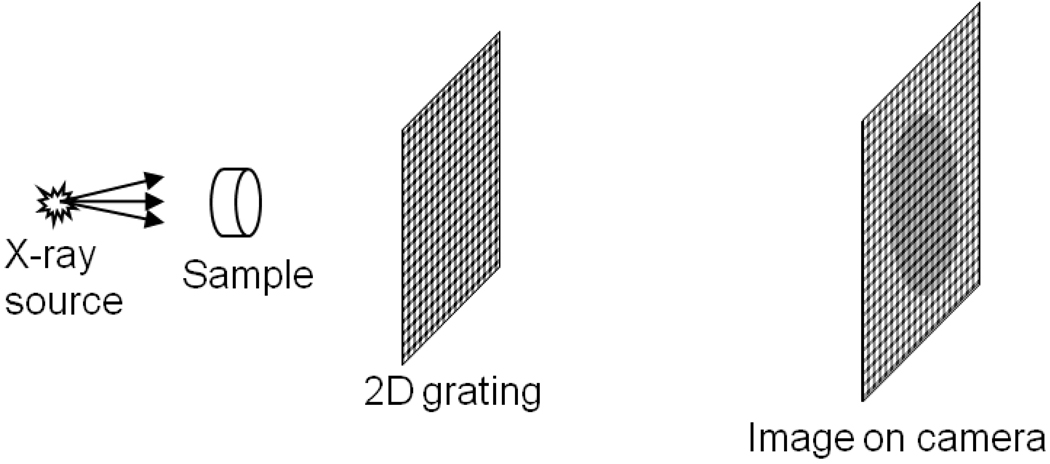
For a variety of applications that require speed, we developed a variant grating-based method to obtain absorption, differential phase-contrast and diffraction from a single raw image, called the spatial harmonic method[13,14]. Here a single transmission grating of lower density is placed in the beam of an x-ray tube[15] (Fig. 1). The imaging device consisted of a 50 Watt tungsten target x-ray tube of 50 µm focal spot size operating at 1 mA/50 kVp/30 sec exposure, an x-ray camera consisting of a 16 bit water-cooled CCD array of matrix size of 2045×2048 and pixel size of 30 µm, coupled to a Gd2O2S:Tb phosphor screen via a 1:1 fiberoptic taper, and a radiography Bucky grid acting as the transmission grating. The source-camera distance was 1.0 meter and the grid was placed exactly midway between the two. Imaged objects were placed at 12.5 cm from the source and magnified 8 times by the cone beam geometry. The grid was a off-the-shelf square Bucky grid of 200 lines-per-inch density (127 µm period). Structurally it was a stack of two orthogonal linear grids made of alternating lead and aluminum stripes. In this setting the fractional Talbot distance was approximately 5 meters for a parallel beam, and extends beyond infinity in the cone beam configuration. Thus the x-rays simply project the grid pattern achromatically onto the camera. The camera resolution was high enough to directly resolve the grid lines. The speed of this approach has permitted in vivo imaging of live animals (manuscript in preparation).
Fig. 1.
The imaging device includes the x-ray tube, the transmission grating, and the x-ray camera. The camera resolution is sufficient to resolve the projected grating lines.
In general a linear grating can only detect refractive bending of x-rays in the direction perpendicular to the grating fringes. Kottler and coauthors showed that measurements in two orthogonal directions are often necessary to retrieve good quality and artifact-free images[16]. Clauser’s patent[7] proposed the use of 2D Talbot gratings for this purpose, but required stringent period and phase matching of the detector elements to the interference patterns to make such measurements. Our spatial harmonic method offers the possibility to do so in a single image without special requirements on the camera.
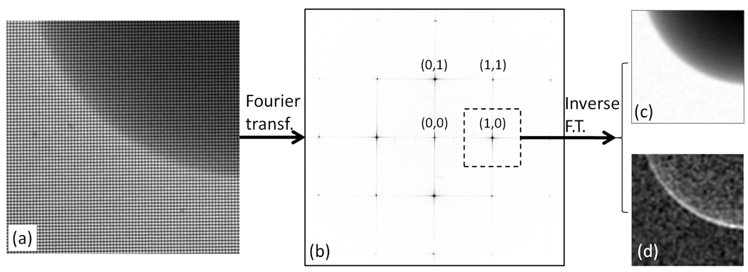
The key question in a single-shot method is how to quantify small changes in the locations and amplitudes of the grating fringes in a pixelated image, when a grating period covers just a few and likely non-integer number of pixels? Fortunately this problem has been solved in the framework of discrete Fourier transformation[17], which converts an image into its spatial frequency spectrum (SFS) (Fig. 2). When a 2D square grating overlays the sample, the SFS of the raw image contains a number of sharp peaks at (2πM/P, 2πN/P), where M and N are integers and P is the period of the grating projection image. We call these the harmonic peaks and label them (M, N). The spatial frequency content of the sample projection image is duplicated at each peak, which provides a harmonic spectrum.
Fig. 2.
The spatial harmonic analysis begins with Fourier transformation of the raw image (a) into the spatial frequency domain (b). The discrete peaks in (b) are spaced by the primary frequencies of the projection of the 2D grating and labeled by their positions. Inverse Fourier transformation of the subregion surrounding the (1,0) peak results in the (1,0) harmonic image. It is a complex image of magnitude (c) and phase (d).
Now we make the basic assumption that the harmonic spectra do not overlap (detailed below). Then, the inverse Fourier transformation of a sub-region centered at a peak yields a corresponding harmonic image (Fig. 2):
| (1) |
where f is the SFS of the raw image. The central (0, 0) harmonic image does not contain grating modulation and therefore not affected by small angle refraction and diffraction effects, but only attenuated by absorption and large angle Compton scattering. The intensity of the (1, 0) and (0, 1) harmonic images measure the amplitude of the vertical and horizontal grating fringes, respectively, and are attenuated by both absorption and diffraction. Therefore, the ratio between these and the (0, 0) harmonic provides diffraction-only images
| (2) |
where the logarithm linearizes the value to the thickness of the sample. Additionally, refractive bending of the x-rays results in changes of the projected positions of the grid lines on the camera, which are defined as the differential phase contrast in grating-based methods[9] similar to Shack-Hartmann wavefront sensing of optical as well as x-ray light[18,19]. Specifically, the shifts of the vertical and horizontal fringes lead to proportional phase shifts of the (1, 0) and (0, 1) harmonic images, respectively. Therefore, differential phase contrast is provided by their phase maps φM,N(x, y). It is important to note from eq.(1) that the resolution of the diffraction and DPC images is the projected period of the grid.
In practice the SFS is modified by the point spread function (PSF) of the phosphor screen in the x-ray camera. The PSF is measured with a narrow transmission slit, and its effect can be corrected by the step f = (SFS of raw image)/(Fourier transform of PSF) for spatial frequencies where the Fourier transformation of the PSF does not diminish. Additionally imperfections in the grating give rise to extraneous values in both the amplitude and phase of the harmonic images. These are removed by the calibration step (calibrated harmonic image) = (original harmonic image)/(grid only harmonic image).
The basic assumption that the harmonic spectra are well separated is met when the cone beam magnification factor G of the sample is sufficiently large such that (G−1)*(focal spot size) > P. This is because the bandwidth each harmonic spectrum is given by 2π/[(G−1) *(focal spot size)], and the separation of the harmonic peaks is 2π/P.
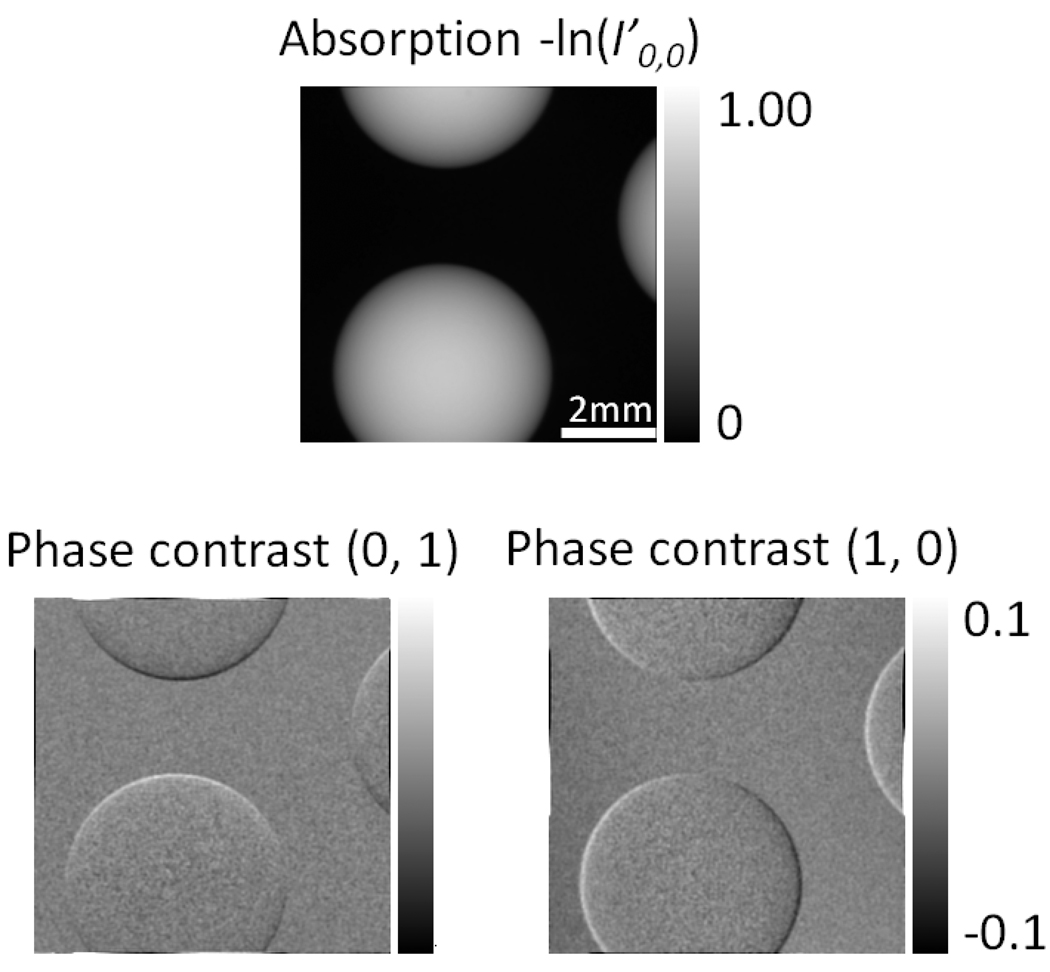
Figure 3 shows DPC and diffraction images of glass beads. The 2 DPC images from the (1,0), (0,1) harmonics highlight different segments of the boundaries of the beads. This has also been observed in previous studies using linear gratings in different orientations[16].
Fig. 3.
The DPC images of glass beads from the (1, 0) and (0, 1) harmonic images (Fig. 2). They are magnified 8 times by the cone beam. Different segments of their boundaries are highlighted in different DPC images.
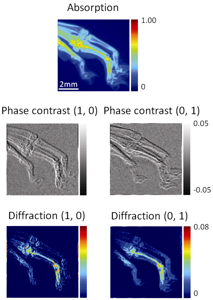
Figure 4 shows the complete set of absorption, DPC and diffraction images of the paw of a dehydrated rat hind limb specimen, which are obtained from a single raw image. The (0, 1) and (1, 0) DPC images emphasize horizontal and vertical interfaces respectively, while interfaces at 45° from horizontal have approximately equal signal in both images.
Fig. 4.
A complete set of results from a single raw image of a rat’s paw include the absorption image derived from the (0, 0) harmonic peak, and the DPC and diffractions images from the (0, 1) and (1, 0) harmonic peaks.
In these experiments the surface radiation dose at the sample was 0.61 mSv, comparable to a human chest lateral radiography[20]. Clinical x-ray tubes have approximately 1000 times the power of our compact tube and therefore can acquire the image in less than 100 ms. The main limitation of this method is that (camera pixel size) < (P/3) such that the camera can resolve the grating pattern. Therefore, the camera resolution limits the density of the grating, and in turn the achievable level of phase contrast[9]. One solution to this limitation is to convert high density grating fringes into a lower density Moiré pattern by the use of a second transmission grating placed on the camera surface[6]. The ultimate solution may be high resolution x-ray cameras. CCD arrays coupled with high resolution x-ray scintillators have demonstrated submicron resolution[21]. This technology may eventually provide large format detectors of several micron resolution that can be used for many applications.
In summary, the spatial harmonic method is able to acquire differential phase contrast and diffraction images in a single exposure without the need for scanning, and allows measurements in multiple directions simultaneously with the use of 2D transmission gratings. Taken together, these characteristics are well suited for fast imaging applications.
References
- 1.Wilkins SW, Gureyev TE, Gao D, Pogany A, Stevenson AW. Phase-contrast imaging using polychromatic hard X-rays. Nature. 1996;384:335–338. [Google Scholar]
- 2.Nugent KA, Gureyev TE, Cookson DF, Paganin D, Barnea Z. Quantitative phase imaging using hard x rays. Physical Review Letters. 1996;77:2961–2964. doi: 10.1103/PhysRevLett.77.2961. [DOI] [PubMed] [Google Scholar]
- 3.Mayo SC, Davis TJ, Gureyev TE, Miller PR, Paganin D, Pogany A, Stevenson AW, Wilkins SW. X-ray phase-contrast microscopy and microtomography. Optics Express. 2003;11:2289–2302. doi: 10.1364/oe.11.002289. [DOI] [PubMed] [Google Scholar]
- 4.Chapman D, Thomlinson W, Johnston RE, Washburn D, Pisano E, Gmur N, Zhong Z, Menk R, Arfelli F, Sayers D. Diffraction enhanced x-ray imaging. Physics in Medicine and Biology. 1997;42:2015–2025. doi: 10.1088/0031-9155/42/11/001. [DOI] [PubMed] [Google Scholar]
- 5.Wernick MN, Wirjadi O, Chapman D, Zhong Z, Galatsanos NP, Yang YY, Brankov JG, Oltulu O, Anastasio MA, Muehleman C. Multiple-image radiography. Physics in Medicine and Biology. 2003;48:3875–3895. doi: 10.1088/0031-9155/48/23/006. [DOI] [PubMed] [Google Scholar]
- 6.Yokozeki S, Suzuki T. Shearing Interferometer Using Grating As Beam Splitter. Applied Optics. 1971;10 doi: 10.1364/AO.10.001575. 1575-&. [DOI] [PubMed] [Google Scholar]
- 7.Clauser JF. 5812629. USA: US Patent. 1998 22 9;
- 8.Momose A, Kawamoto S, Koyama I, Hamaishi Y, Takai K, Suzuki Y. Demonstration of X-Ray Talbot interferometry. Japanese Journal of Applied Physics Part 2-Letters. 2003;42:L866–L868. [Google Scholar]
- 9.Weitkamp T, Diaz A, David C, Pfeiffer F, Stampanoni M, Cloetens P, Ziegler E. X-ray phase imaging with a grating interferometer. Optics Express. 2005;13:6296–6304. doi: 10.1364/opex.13.006296. [DOI] [PubMed] [Google Scholar]
- 10.Pfeiffer F, Kottler C, Bunk O, David C. Hard X-ray phase tomography with low-brilliance sources. Physical Review Letters. 2007;98 doi: 10.1103/PhysRevLett.98.108105. [DOI] [PubMed] [Google Scholar]
- 11.Pfeiffer F, Bech M, Bunk O, Kraft P, Eikenberry EF, Bronnimann C, Grunzweig C, David C. Hard-X-ray dark-field imaging using a grating interferometer. Nature Materials. 2008;7:134–137. doi: 10.1038/nmat2096. [DOI] [PubMed] [Google Scholar]
- 12.Olivo A, Arvanitis CD, Bohndiek SE, Clark AT, Prydderch M, Turchetta R, Speller RD. First evidence of phase-contrast imaging with laboratory sources and active pixel sensors. Nuclear Instruments & Methods in Physics Research Section A-Accelerators Spectrometers Detectors and Associated Equipment. 2007;581:776–782. [Google Scholar]
- 13.Wen H, Bennett E, Hegedus MM, Carroll SC. Spatial harmonic imaging of x-ray scattering - initial results. IEEE Transactions on Medical Imaging. 2008;27:997–1002. doi: 10.1109/TMI.2007.912393. [DOI] [PMC free article] [PubMed] [Google Scholar]
- 14.Wen H, Bennett EE, Hegedus MM, Rapacchi S. Fourier x-ray scattering radiography yields bone structural information. Radiology. 2009;252:910–918. doi: 10.1148/radiol.2521081903. [DOI] [PMC free article] [PubMed] [Google Scholar]
- 15.Wang ZT, Huang ZF, Zhang L, Kang KJ, Zhu PP. Fast X-Ray Phase-Contrast Imaging Using High Resolution Detector. IEEE Transactions on Nuclear Science. 2009;56:1383–1388. [Google Scholar]
- 16.Kottler C, David C, Pfeiffer F, Bunk O. A two-directional approach for grating based differential phase contrast imaging using hard x-rays. Optics Express. 2007;15:1175–1181. doi: 10.1364/oe.15.001175. [DOI] [PubMed] [Google Scholar]
- 17.Gonzalez RC, Woods RE. Digital Image Processing. New Jersey: Prentice Hall, Upper Saddle River; 2007. [Google Scholar]
- 18.Platt BC, Shack R. History and principles of Shack-Hartmann wavefront sensing. Journal of Refractive Surgery. 2001;17:S573–S577. doi: 10.3928/1081-597X-20010901-13. [DOI] [PubMed] [Google Scholar]
- 19.Mayo SC, Sexton B. Refractive microlens array for wave-front analysis in the medium to hard x-ray range. Optics Letters. 2004;29:866–868. doi: 10.1364/ol.29.000866. [DOI] [PubMed] [Google Scholar]
- 20.Martin CJ. Radiation dosimetry for diagnostic medical exposures. Radiation Protection Dosimetry. 2008;128:389–412. doi: 10.1093/rpd/ncm495. [DOI] [PubMed] [Google Scholar]
- 21.Koch A, Raven C, Spanne P, Snigirev A. X-ray imaging with submicrometer resolution employing transparent luminescent screens. Journal of the Optical Society of America A-Optics Image Science and Vision. 1998;15:1940–1951. [Google Scholar]


