Abstract
Spatiotemporal control of excitable media is of paramount importance in the development of new applications, ranging from biology to physics. To this end, we identify and describe a qualitative property of excitable media that enables us to generate a sequence of traveling pulses of any desired length, using a one-time initial stimulus. The wave trains are produced by a transient pacemaker generated by a one-time suitably tailored spatially localized finite amplitude stimulus, and belong to a family of fast pulse trains. A second family, of slow pulse trains, is also present. The latter are created through a clumping instability of a traveling wave state (in an excitable regime) and are inaccessible to single localized stimuli of the type we use. The results indicate that the presence of a large multiplicity of stable, accessible, multi-pulse states is a general property of simple models of excitable media.
Excitable media are characterized by a large (finite amplitude) response to a supra-threshold perturbation of the rest state, followed by decay back to the same rest state [1]. Such behavior is frequently found in biological [2], chemical [3], and physical [4] systems. As suggested independently by FitzHugh and Nagumo [5], temporal excitable behavior can be understood qualitatively via a prototype two-component ordinary differential equation of Bonhoeffervan der Pol type with a cubic nonlinearity in the activator field [1]. In spatially extended excitable media with activator diffusion, such a perturbation results in the formation of a solitary traveling wave, hereafter referred to as a traveling pulse [1]. Since the medium returns to the rest state after the passage of the pulse, repeated stimulation is required to generate a sequence of pulses [6, 7]. Here we identify a novel property of excitable systems of this type that allows us to generate economically sequences of traveling pulses through a one-time initial stimulus, whose shape controls the number of pulses within the wave train.
In a comoving frame, the one-dimensional (1D) profile of a traveling pulse corresponds, in many systems, to a Shil’nikov homoclinic orbit [8–12]. Such orbits are known to be accompanied by (an infinite number of) additional multi-pulse homoclinic orbits [7, 9, 13], and these in turn correspond to spatially localized groups of pulses (hereafter finite pulse trains) traveling together with common speed. This speed differs in general from the speed of a single pulse. All of these states form close to the parameter values at which the primary homoclinic orbit is present [9, 11] and have similar speeds. In contrast, there are also spatially extended states (hereafter infinite pulse trains) consisting of copies of the single pulse state, in which each pulse is locked to the oscillatory tail of the preceding pulse [10, 14]. Many different states consisting of equally or unequally spaced pulses are possible, each traveling at its own speed [6,7, 10, 13, 15]. Although solutions of either type are readily constructed using ideas from spatial dynamics, their stability properties are in general unknown [7, 10, 12, 13, 15]. Moreover, even when the solutions are stable, no robust procedures are known for generating a pulse train of a desired type or length without continued input.
In this letter, we demonstrate that in spatially extended homogeneous excitable media, distinct families of multi-pulse states can be simultaneously stable, and explain how the different states may be generated. Of these the fast pulse trains can be generated with great selectivity by suitably tuned onetime perturbations, via the formation of a transient pacemaker. We show how to mold the initial perturbation to achieve the desired result. The basic idea is simple: a one-time perturbation evolves first in amplitude and so forms a localized standing oscillation, i.e., a pacemaker. If this oscillation is in turn unstable to decay into solitary waves, the pacemaker is transient and the number of pulses generated by the perturbation is finite. In contrast, the slow pulse trains are the result of a long wavelength “clumping” instability of the traveling waves state. The results are obtained in one spatial dimension, but qualitatively similar results hold in two dimensions.
Model equations
In two-component models an oscillatory instability of a homogeneous state necessarily comes in with a zero wave number at onset and hence produces spatially uniform oscillations [16]. This is not the case for three-component models [17]. In the following we focus on a system of this type that is known to support, under identical conditions, both traveling solitary pulses and spontaneous pacing activity [18]:
| (1a) |
| (1b) |
| (1c) |
Here u(x, y, t) can be thought of as an activator and v(x, y, t) as an inhibitor; the latter is in turn controlled by a third component w(x, y, t), also generated in response to the activator. When aw = 0, eqs. (1a) and (1b) reduce to the standard FitzHugh-Nagumo (FHN) form [1]. In what follows we set aw = 0.5, and adopt the parameters εv = 0.2, εw = 1.0, a0 = −0.1, D = 0.005, with av used as a control parameter.
Uniform and nonuniform solutions
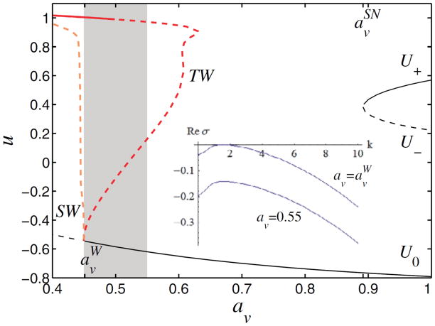
Equations (1) admit three spatially homogeneous solutions referred to as U0, U−, U+; the U± arise through a saddle-node bifurcation at av = aSNv ≃ 0.8919 and are present for av > avSN only (see fig. 1). In excitable media the rest state, here U0 ≡ (u0, v0, w0), has to be stable to infinitesimal perturbations,
Figure 1.
(Color online) Bifurcation diagram for spatially homogeneous steady (U0, U±, thin black lines) and oscillatory (heavy light colour lines) solutions of eqs. (1). Oscillatory branches of standing waves (SW) and traveling waves (TW) with fixed spatial period λc ≡ 2π/kc ≃ 4.07 are shown in terms of the maximum value umax of u(x, t), and emerge from a finite wave number Hopf bifurcation of U0 ≡ (u0, v0, w0) at av ≡ avW ≃ 0.4497. Solid (dashed) lines indicate stable (unstable) solutions. The shaded region, 0.4497 ≲ av ≲ 0.55, delimits the existence of stable pulse trains of fast type. The inset represents the dispersion relation at onset (av = aWv, kc ≃ 1.54, ωc ≃ 0.4, with TW phase velocity cTWc ≃ 0.26) and near the rightmost limit of the shaded region, av = 0.55, where U0 is linearly stable.
| (2) |
Here σ is the (complex) perturbation growth rate, k > 0 is the wave number, and c.c. denotes a complex conjugate. Linear stability analysis (δ ≪ 1) shows that U0 is stable for av > aWv ≃ 0.4497 (the excitable regime) but unstable for av < aWv (see inset in fig. 1). The bifurcation at av = aWv is a Hopf bifurcation with finite wave number kc ≃ 1.54 at onset. The corresponding critical frequency is ωc ≃ 0.4. Standard theory [19] now shows that two branches of oscillatory states with spatial period λc ≡ 2π/kc ≃ 4.07 bifurcate from the rest state at av = aWv, a branch of traveling waves (TW) and a branch of standing waves (SW)Note 1. As shown in fig. 1, both branches bifurcate subcritically (i.e., in the av > avW direction) but eventually turn towards small av; for SW, the subcritical regime is very small. It follows that near onset the TW are once unstable, while the SW are twice unstable. Moreover, the TW acquire stability with respect to wavelength λc perturbations once the TW branch turns around towards smaller av, while the SW remain unstable to TW perturbations. We shall see, however, that the TW are in fact unstable beyond the saddle-node (av ≃ 0.63) with respect to long wavelength perturbations (fig. 1). These instabilities accumulate at av ≈ 0.5 so that the TW are stable with respect to all perturbations for av ≲ 0.5 only, cf. [21].
Generation of pulse trains
In addition to the spatially periodic SW and TW states eqs. (1) also admit different types of single-pulse and multi-pulse solutions. In a comoving reference frame these states correspond to homoclinic orbits, i.e., to solutions asymptotic to U0 as ξ → ± ∞. There are in fact two families of such states referred to in what follows as slow and fast, based on their speed of propagation relative to that of the TW.
Slow pulse trains
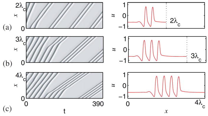
Formation of the slow pulse trains is associated with the long wavelength instability of the TW (fig. 1). These instabilities are present in the regime 0.5 ≲ av ≲ 0.63 and the number of slow pulses that results depends on the length L of the periodic domain used to solve eqs. (1). For example, for av = 0.6 a bound state of two pulses is generated when the domain period is L = 2λc, while groups of three and four pulses form when L = 3λc, and L = 4λc, respectively (fig. 2). These pulse trains propagate with speeds c ≃ 0.08 that are substantially slower than cTW ≃ 0.17, as indicated by the dramatic change in slope of the space-time trajectories of each crest as the instability evolves. The corresponding solution profiles are shown in the right set of panels in fig. 2. No single traveling pulses are generated for this parameter choice, presumably because the TW are stable in an L = λc periodic domain.
Figure 2.
(Color online) The “clumping” instability of traveling waves and the formation of finite pulse trains at av = 0.6 in small periodic domains with period (a) L = 2λc ≃ 8.14, (b) L = 3λc ≃ 12.21, and (c) L = 4λc ≃ 16.28. The background state filling the domain corresponds to the homogeneous state U0 ≡ (u0, v0, w0) ≃ (−0.650, −0.375, −0.650). Left panels: space-time plots with x along the vertical axis and time horizontally (dark colour indicates larger values of the u field). Right panels: profiles of finite pulse trains at t = 390, traveling without change towards the right.
We may think of the resulting instability as a “clumping” instability, and believe that it is a consequence of the fact that the fastest growing mode in an L = nλc domain is the mode with wavelength nλc. This property is characteristic of a phase-like instability called the Eckhaus-Benjamin-Feir instability except that here this instability does not result in phase slips [22]: instead when the wave amplitude falls locally to sub-threshold value the system nucleates the rest state U0. The result is evolution into a clumped state that conserves the number of crests.
Fast pulse trains
The fast pulse trains, on the other hand, are generated not by linear instability but in response to a one-time finite amplitude spatially localized perturbation. Such perturbations evolve more rapidly in amplitude than in phase and hence result in a spatially localized standing oscillation. These, like the spatially periodic SW, are in turn unstable to TW perturbations. Thus in the shaded region in fig. 1, suitably chosen finite amplitude perturbations evolve into transient pacemakers whose decay time controls the length of the pulse train that is emitted. As a result, the number of pulses in the wave train is now controlled by the decay time of the pacemaker and hence the shape of the initial perturbation, instead of the imposed spatial period, L.
To demonstrate the development of distinct but finite pulse trains in large domains (L ≫ λc) by the above mechanism, we focus on the parameter regime in which both U0 and TW are linearly stable, i.e., 0.45 ≲ av ≲ 0.5. In what follows, we consider eqs. (1) with Neumann boundary conditions on the 1D domain 0 ≤ x ≤ L, and examine the effect of different initial perturbations on pacemaker emergence and the resulting solutions. The perturbations have a smoothed top-hat profile centered at x = 0,
| (3) |
where A denotes the amplitude of the perturbation, R ≪ L its width, and Δ ≲ R measures the steepness of the initial interface. When av > avW and A ~ 0.1, R ~ 1, the excitability threshold is locally exceeded and the system responds with a single propagating pulse. Figure 3(a), shows the propagation of such a pulse in a space-time plot (left panel) with an enlargement of the initial phase (middle panel) and the spatial pulse profile (right panel). The figure shows that the initial perturbation grows abruptly in place before decaying into a propagating pulse. Once in motion, the profile of the pulse becomes distinctly asymmetrical, with a train of spatially decaying oscillations towards its rear, as expected of a Shil’nikov saddle-focus [8].
Figure 3.
(Color online) Solutions of eqs. (1) at av =0.5 with Neumann boundary conditions at x=0, x= 40 using different stimuliat t=0: (a) A=0.3, R=1, (b) A=0.3, R=0.4, both for Δ=0.1. Left panels: space-time plots with x along the vertical axis and time horizontally (dark colour indicates larger values of the u field). Middle panels: enlargement of the space-time plots in vicinity of the initial perturbation, x ∈ [0, 1], demonstrating (a) the initial growth of the disturbance in amplitude from u = u0 +A<0 to u ~ 1, followed by its decay when the initial perturbation is broad, and (b) the formation and eventual decay of a transient pacemaker when the initial perturbation is narrower; the dashed line in (b) is at x=0.25. Each oscillation of the pacemaker generates one pulse. Right panels: profiles of (a) single-pulse and (b) three-pulse states, both traveling without change towards the right.
While such single pulse profiles are known from the two-variable FHN system [1, 12], the three-variable model (eqs. (1)) allows the generation of more complicated solutions such as N-homoclinic orbits of Shil’nikov type [9]. To observe these states, we decrease the stimulus width to R = 0.4. This initial perturbation sets up a transient pacemaker and the system now generates a finite pulse train (fig. 3(b), left panel), even though no additional stimulation is applied after t = 0. The middle panel of fig. 3(b) shows that the pacemaker oscillates in the form of a standing oscillation in 0 ≤ x ≲ 0.25 for three cycles, before decaying. Each oscillation cycle that exceeds the excitability threshold results in the generation of a traveling pulse. Consequently an initial stimulus with A = 0.3, R = 0.4 triggers three pulses moving together as a group (see fig. 3(b)).
Numerically, we find that the single pulse in fig. 3(a) propagates with speed cpulse ≃ 0.2482, while the pulse trains all propagate with essentially identical and slightly larger speed c ≃ 0.2487, to within numerical error of order of 10−5. Both velocities are substantially larger than the phase velocity of the TW, cTW ≃ 0.1877 at av = 0.5. Consequently we call the resulting finite pulse trains fast. Comparison with fig. 2 shows that the fast pulses are much broader than the slow pulses, but otherwise resemble each other.
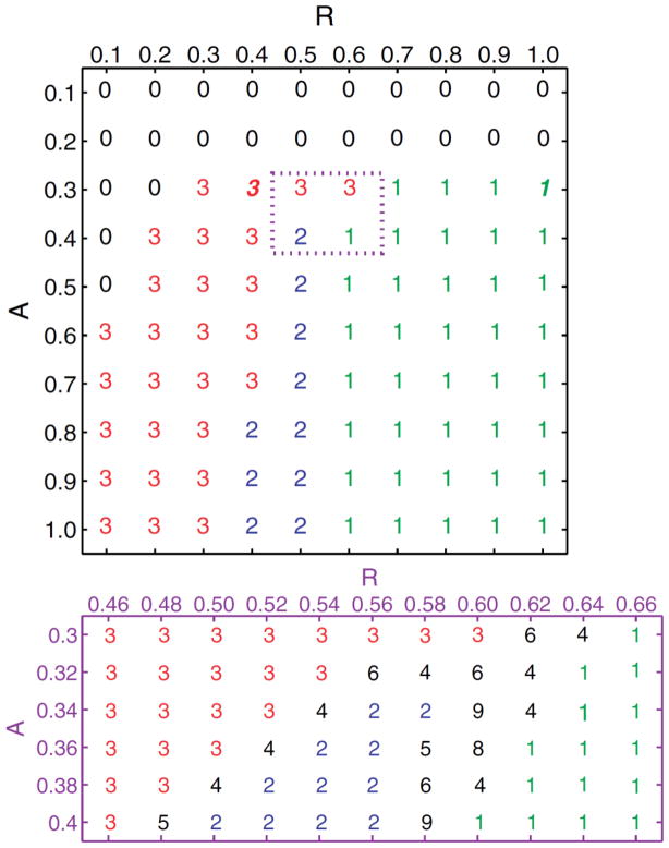
The finite pulse trains accessible by varying the amplitude A and width R of the initial perturbation are summarized in fig. 4. In the vicinity of the extinction boundary the number of pulses increases, albeit in a nonmonotonic fashion, and this property of the system can be exploited to identify empirically the initial conditions that result in the desired number of pulses. In the bottom panel of fig. 4 we provide a more detailed sample of the possible outcomes. Evidently the number of pulses is very sensitive to the form of the initial perturbation, and this sensitivity extends to the dependence of the results on the length scale Δ introduced in eq. (3).
Figure 4.
Top panel: finite fast pulse trains computed from the initial perturbation (3) with Δ = 0.1 for different values of A and R when av = 0.5. The integers correspond to the number N of pulses in the wave train, the bold italic fonts corresponding to the solutions described in fig. 3. Bottom panel: variation in N in the vicinity of the extinction boundary, in the region indicated by the small rectangle in the top panel. The numerical integration of eqs. (1) was performed with Δx = 0.005 and Neumann boundary conditions on an L = 50 domain.
Qualitatively similar results are found for other parameterized families of initial conditions, provided these broadly resemble the top-hat profile in eq. (3).
Bistability between different pulse trains
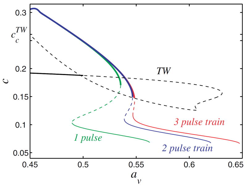
The similarity in the pulse profiles suggests that the two families of finite pulse trains may in fact be related. This supposition is supported by our numerical simulations, which show that stable pulse trains of slow and fast type may coexist, cf. [18]. To identify the connection between these two families, we have again employed numerical continuation [20] but this time initiated with single, double and triple homoclinic profiles of fast type, such as those shown in fig. 3. In fig. 5, we show that the slow and fast pulse trains are in fact separated by unstable branches (dashed lines). This result explains why we find two families of traveling pulse trains, and why we observe bistability between them. Observe that the fast pulse trains all travel with essentially the same speed c as av decreases, and do so over a broad interval of av values. This is the case for all the multi-pulse states shown in fig. 4. This fact facilitates the insertion of additional pulses into a pulse train through incremental changes in the initial stimulus. The resulting selectivity is a consequence of the large multiplicity of coexisting stable pulse trains and the intertwined structure of their basins of attraction. In contrast, the branches of slow pulse trains all turn around towards smaller av as c decreases (not shown), and in so doing follow the behavior of the TW branch.
Figure 5.
(Color online) The speed c of the fast (heavy colour lines) and slow (thin colour lines) pulse trains as a function of av together with the phase speed of traveling wave (TW) states. Only three branches of traveling pulse trains are shown. The phase speed of the TW lies between the speeds of the fast and slow pulse trains. Solid (dashed) lines indicate stable (unstable) states. The accumulation of the saddle-nodes of the fast pulse trains (av ≈ 0.55) defines the upper boundary of the shaded region displayed in fig. 1. The pulse trains were computed in a comoving frame, on a periodic domain with L = 100.
The results in fig. 5 help us to understand the observed absence of fast pulse trains at av = 0.6, and suggest that the empirically determined upper boundary of the shaded region in fig. 1, i.e., the region within which finite amplitude perturbations generate finite pulse trains, is determined by the accumulation point of the saddle-node bifurcations at which the fast pulse trains lose stability and cease to exist. As seen in the figure, these saddle-node bifurcations accumulate at av ≃ 0.55, an observation that can be confirmed by numerical continuation of the additional multi-pulse states shown in fig. 4. This value is close to that at which the TW solutions acquire stability with respect to wavelength 2λc perturbations but is not related to it. Numerically we find that in av ≲ 0.55 the finite amplitude perturbations always reach fast pulse trains, even when these coexist with stable slow pulse trains. Figure 5 also shows that for av ≳ 0.55 slow pulse trains, including the missing slow single-pulse state in L = λc domains, should be reachable by appropriate finite amplitude perturbations of U0.
Generation of finite trains of target waves
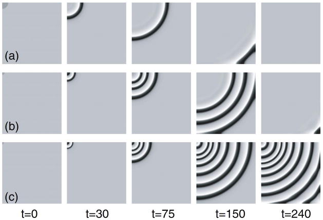
We now turn to the corresponding results in two spatial dimensions (2D), with Neumann boundary conditions on a square domain. The initial perturbation is taken to be spot-like and centered at the top-left corner of the domain, as shown in fig. 6; the parameter Rnow measures its extent in the radial direction.
Figure 6.
(Color online) Solutions of eqs. (1) in the (x, y) plane with av = 0.5, using different initial stimuli. Dark colour implies larger values the u field; the propagation direction is from the top-left corner to the bottom-right corner. (a) Single wave propagation for R = 2.0. (b) Transient pacing and the formation of a finite number of target waves for R = 0.8. (c) Formation of a stable pacemaker and persistent target wave emission for R = 0.6. In all cases the perturbation amplitude is A = 0.3, with Δ = 0.1; the physical domain size is 20 × 20 with Neumann boundary conditions, and Δx = Δy = 0.005.
The two types of behavior, propagation of a single target wave (see fig. 6(a)) and of a finite train of target waves due to transient pacing activity (see fig. 6(b)), persist also in 2D; the spatial cross-sections of these states along the propagation diagonal (figs. 6(a, b)) admit profiles that resemble the profiles of fast family type obtained in 1D (see fig. 3). The value of R required for the finite target waves is now larger (R ~ 1) than in the 1D case, but with increasing R single-pulse propagation results, as in 1D. However, in contrast to 1D a one-time perturbation with a small value of R produces persistent pacing activity that results in standard target waves (see fig. 6(c)) [18]. These results are not affected by the choice of partial domain and apply equally to a large square domain with a spot-like perturbation in the center. We attribute the differences between the 1D and 2D results to curvature effects in the pacemaker region.
Conclusions
We have demonstrated that stable multi-pulse solutions can be generated in a spatially extended excitable medium by a one-time stimulus, with no need for additional stimulation. These finite pulse trains are the result of the formation of a transient pacemaker with decaying amplitude that generates solitary waves while its amplitude remains above threshold for pulse generation. The primary requirement for this property of the system is a nonlinear (subcritical) instability of the uniform state to both traveling waves (TW) and standing waves (SW), as in fig. 1. We have seen that under these conditions stable multi-pulse states are present, and that the basins of attraction of these states can be selected by a suitably tailored initial stimulus through the excitation of a transient pacemaker. We believe these results to be independent of the details of the system used here, and thus characteristic of a broad class of excitable systems.
In the present example the pulse trains generated by the transient pacemaker propagate with a speed substantially larger than the coexisting spatially periodic TW, and may also coexist with a distinct family of traveling pulses that propagate more slowly than the TW. The latter form as a result of a long wavelength “clumping” instability of the TW that is also a consequence of the subcriticality of the TW branch. However, the slow pulse trains are not accessible by finite amplitude perturbations of the rest state of the type we use.
The study was conducted within the phenomenological framework of a three-variable FitzHugh-Nagumo–type model [18], and employed bifurcation analysis, numerical continuation, and parametrized stimuli to generate a variety of finite pulse trains, as summarized in fig. 4. These results demonstrate that near the extinction boundary the length N of the fast pulse train becomes a sensitive function of the shape of the initial stimulus, enabling us to “dial in” different pulse trains by appropriately shaping the initial stimulus. The details of the resulting look-up table (fig. 4) are system-specific but need only be computed once; similar look-up tables can be established empirically for each model of interest. As shown in figs. 6(a, b), these results extend to two space dimensions as well.
We speculate that this intriguing property of excitable systems may provide new insights into a number of applied science processes exhibiting reaction-diffusion behavior [1, 17, 23], including chemical reactions [3], excitation and propagation of signals in neurons and cardiac tissue, and intracellular calcium cycling [2]. Technological applications to information transfer using nonlinear optical systems [24] and to unconventional computation based on reaction-diffusion systems [25] are also possible.
Acknowledgments
This work was supported by NIH/NHLBI Grant P01 HL078931 and by National Science Foundation Grant DMS-0605238.
Footnotes
The TW were computed in the comoving frame ξ ≡ x – cTWt, i.e., by replacing ∂t in eqs. (1) by – cTW∂ξ, and ∂x by ∂ξ. In this frame the TW corresponds to a periodic orbit with period λc, with the speed c = cTW of the waves computed as a nonlinear eigenvalue using the numerical continuation package AUTO [20]. Temporal stability was computed via a standard numerical eigenvalue method using the time-dependent version of eqs. (1) in the comoving frame. The SW branch was computed via direct integration of eqs. (1) in 0 ≤ x ≤ λc/4 with Neumann boundary conditions at x = 0 and Dirichlet boundary conditions at x = λc/4, to suppress the instability of the SW with respect to TW perturbations.
References
- 1.Tyson JJ, Keener JP. Physica D. 1988;32:327. [Google Scholar]; Meron E. Phys Rep. 1992;218:1. [Google Scholar]; Cross MC, Hohenberg PC. Rev Mod Phys. 1993;65:851. [Google Scholar]
- 2.Keener J, Sneyd J. Mathematical Physiology. New York: Springer-Verlag; 1998. [Google Scholar]; Murray JD. Mathematical Biology. New York: Springer-Verlag; 2002. [Google Scholar]
- 3.Epstein IR, Pojman JA. An Introduction to Nonlinear Chemical Dynamics: Oscillations, Waves, Patterns and Chaos. New York: Oxford University Press; 1998. [Google Scholar]
- 4.Coullet P, Frisch T, Gilli JM, Rica S. Chaos. 1994;4:485. doi: 10.1063/1.166026. [DOI] [PubMed] [Google Scholar]; Schenk CP, et al. Phys Rev Lett. 1997;78:3781. [Google Scholar]; Tredicce JR. In: AIP Conf Proc. Krauskopf B, Lenstra D, editors. Vol. 548. New York: AIP, Melville; 2000. p. 238. [Google Scholar]
- 5.FitzHugh R. Biophys J. 1961;1:445. doi: 10.1016/s0006-3495(61)86902-6. [DOI] [PMC free article] [PubMed] [Google Scholar]; Nagumo JS, Arimoto S, Yoshizawa S. Proc IRE. 1962;50:2061. [Google Scholar]
- 6.Elphick C, Meron E, Rinzel J, Spiegel EA. J Theor Biol. 1990;146:249. doi: 10.1016/s0022-5193(05)80138-9. [DOI] [PubMed] [Google Scholar]
- 7.Or-Guil M, Kevrekidis IG, Bär M. Physica D. 2000;135:154. [Google Scholar]
- 8.Guckenheimer J, Holmes P. Nonlinear Oscillations, Dynamical Systems, and Bifurcations of Vector Fields. New York: Springer-Verlag; 1983. [Google Scholar]
- 9.Glendinning P, Sparrow CT. J Stat Phys. 1984;35:645. [Google Scholar]
- 10.Balmforth NJ. Annu Rev Fluid Mech. 1995;27:335. [Google Scholar]
- 11.Spina A, Toomre J, Knobloch E. Phys Rev E. 1998;57:524. [Google Scholar]
- 12.Champneys AR, et al. SIAM J Appl Dyn Syst. 2007;6:663. [Google Scholar]
- 13.Feroe JA. SIAM J Appl Math. 1982;42:235. [Google Scholar]
- 14.Elphick C, Meron E, Spiegel EA. Phys Rev Lett. 1988;61:496. doi: 10.1103/PhysRevLett.61.496. [DOI] [PubMed] [Google Scholar]
- 15.Rinzel J, Keller JB. Biophys J. 1973;13:1313. doi: 10.1016/S0006-3495(73)86065-5. [DOI] [PMC free article] [PubMed] [Google Scholar]; Keener JP. SIAM J Appl Math. 1982;39:528. doi: 10.1137/140983872. [DOI] [PMC free article] [PubMed] [Google Scholar]; Maginu K. SIAM J Appl Math. 1985;45:750. [Google Scholar]; Kobayashi R, Ohta T, Hayase Y. Physica D. 1995;84:162. [Google Scholar]; Bordiougov G, Engel H. Phys Rev Lett. 2003;90:148302. doi: 10.1103/PhysRevLett.90.148302. [DOI] [PubMed] [Google Scholar]; Manz N, Hamik CT, Steinbock O. Phys Rev Lett. 2004;92:248301. doi: 10.1103/PhysRevLett.92.248301. [DOI] [PubMed] [Google Scholar]; Röder G, Bordyugov G, Engel H, Falcke M. Phys Rev E. 2007;75:036202. doi: 10.1103/PhysRevE.75.036202. [DOI] [PubMed] [Google Scholar]
- 16.Ohta T, Hayase Y, Kobayashi R. Phys Rev E. 1996;54:6074. doi: 10.1103/physreve.54.6074. [DOI] [PubMed] [Google Scholar]
- 17.Falcke M, Or-Guil M, Bär M. Phys Rev Lett. 2000;84:4753. doi: 10.1103/PhysRevLett.84.4753. [DOI] [PubMed] [Google Scholar]; Yang L, Zhabotinsky AM, Epstein IR. Phys Chem Chem Phys. 2006;8:4647. doi: 10.1039/b609214d. [DOI] [PubMed] [Google Scholar]
- 18.Stich M. PhD Thesis. Technische Universität; Berlin: 2003. [Google Scholar]
- 19.Knobloch E. Phys Rev A. 1986;34:1538. doi: 10.1103/physreva.34.1538. [DOI] [PubMed] [Google Scholar]; Crawford JD, Knobloch E. Annu Rev Fluid Mech. 1991;23:341. [Google Scholar]
- 20.Doedel E, et al. AUTO2000: Continuation and bifurcation software for ordinary differential equations. http://indy.cs.concordia.ca/auto/
- 21.Mercader I, Alonso A, Batiste O. Eur Phys J E. 2004;15:311. doi: 10.1140/epje/i2004-10071-7. [DOI] [PubMed] [Google Scholar]
- 22.Janiaud B, et al. Physica D. 1992;55:269. [Google Scholar]; Liu Y, Ecke RE. Phys Rev E. 1999;59:4091. [Google Scholar]
- 23.Aranson I, Levine H, Tsimring L. Phys Rev Lett. 1996;76:1170. doi: 10.1103/PhysRevLett.76.1170. [DOI] [PubMed] [Google Scholar]; Schenk CP, Or-Guil M, Bode M, Purwins HG. Phys Rev Lett. 1997;78:3781. [Google Scholar]
- 24.Coullet P, Daboussy D, Tredicce JR. Phys Rev E. 1998;58:5347. [Google Scholar]; Lu W, Yu D, Harrison RG. Opt Lett. 1999;24:578. doi: 10.1364/ol.24.000578. [DOI] [PubMed] [Google Scholar]
- 25.Igarashi Y, Gorecki J, Gorecka JN. In: Unconventional Computation. Calude CS, et al., editors. Berlin: Springer-Verlag; 2006. p. 130. [Google Scholar]; Gorecka J, Gorecki J. J Chem Phys. 2006;124:84101. doi: 10.1063/1.2170076. [DOI] [PubMed] [Google Scholar]


