

There has been considerable effort devoted to developing technology for interfacing with the central nervous system in laboratory animals and humans [1-2]. Even though these efforts have led to marvelous technological advancements in circuits and systems, some of the resulting devices may find little use in their application domain, because the specifics of the targeted applications or the realistic needs of the end users may not be taken into account.
Neural interfacing technology can be applied to two major areas: neurological diseases (clinical) and neurosciences (research). Devices that target the former, i.e. neuroprostheses, need to be chronically implantable, extremely safe, and highly reliable to be used in humans as part of a therapeutic procedure. Size, power consumption, and carrier frequency are highly constrained due to implantation requirements. Cochlear implants and deep-brain stimulators (DBS) are examples of neuroprostheses with undeniable positive outcomes [3]. On the other hand, devices that target neuroscience research do not necessarily need to be implantable. However, they have to compete with sophisticated instruments that are currently in use by the neuroscience community [4]. These devices should at least provide the same quality and quantity of information as their older counterparts, while resolving some of their limitations, such as eliminating hardwires. For instance, a device that utilizes the UWB band (3.1-to-10.6GHz) for wireless communication is not suited for implantation and clinical applications, while data reduction and classification by simple on-chip DSP is not sufficient for most research purposes [5].
We introduced a Wireless Integrated Neural Recording system (WINeR-5) in [6] as a substitute for hardwires in recording setups from freely moving animals in behavioral neuroscience research applications. This removes a source of motion artifacts and bias in the experimental results due to psychological effects of tethering. However, a key limitation of WINeR-5 and many similar wireless systems is the need for the animal subject to carry a payload of batteries. This may not matter when recording from costly primates [7]. However, most labs use small animals such as rats and mice, for which there will be a compromise between the size/weight of the headstage and the uninterrupted duration of experiments. Here we report the first closed-loop inductively powered wireless integrated neural recording system-on-a-chip (WINeR-6) for research applications, which can simultaneously record from 32-channels for an unlimited period of time without losing any piece of information.
Figure 6.4.1 shows the WINeR-6 block diagram and its test setup. Neural signals are amplified and filtered by an array of capacitively coupled fully differential LNAs with adjustable gain (67.8/78dB) and bandwidth (HPF: 0.1Hz-1kHz/LPF: 8kHz) [6]. Our prior experience with WINeR-5 showed that although each LNA consumes a small current (∼25μA), since there are 32 of them, the LNA block quickly becomes the dominant power consumer (42%). This condition is exacerbated with an increased number of channels. To address this issue, we employ a power-scheduling mechanism, depicted in Fig. 6.4.2, that puts most of the LNAs that are not being sampled in sleep mode with a fraction of their active current consumption (0.5μA). We do not completely turn the LNAs off to reduce the transient time, tT, for a dormant LNA to reach its active state ahead of each sampling. The number of LNAs that should be activated ahead of sampling, N, depends on the overall sampling rate, fS, which in turn depends on the desired neural signal bandwidth (N > fStT). In WINeR-6, N is programmable by bits SR0:2, which change the number of consecutive ‘1’s in a circular shift register (CSR) that activates the LNAs. The last circulating ‘1’ indicates the channel that is ready to be sampled. A key advantage of this mechanism over [5], in which the 1st stage is always on, is its robustness against stimulus artifacts. Artifact rejection will be necessary in future revisions of the WINeR system, which will have stimulation capability.
Figure 6.4.1.
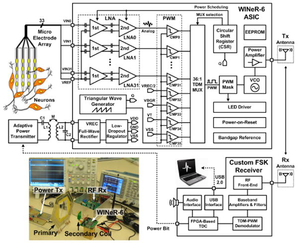
WINeR-6 overall system block diagram. Inset: Measurement setup.
Figure 6.4.2.

Power scheduling keeps the majority of LNAs in the sleep mode using a circular shift register. A programmable number of the LNAs, which need to be turned on ahead of sampling, are moved to the active mode at any time.
Amplitude-to-time conversion (ATC) is done by comparing the last active LNA output with a precision triangular waveform, whose frequency and VP-P (VLow–VHigh) can be adjusted by the user to indicate fS and input dynamic range, respectively. Four monitoring signals (VREC/2, VSS, VBG, VT) are also sampled along with 32 LNA outputs in each 36-pulse TDM-PWM packet to close the inductive power control loop and monitor the ASIC functionality and temperature. These signals also provide a unique pattern that indicates the beginning of each TDM-PWM packet on the Rx.
The TDM-PWM signal drives the Tx block, which includes a VCO with an off-chip inductor followed by a PA (Fig. 6.4.3). Changes in the loading and reflected RF signal result in undesired VCO frequency shifts in WINeR-5 when the animal is moving in the cage. We resolve this problem by adding the nonlinear class-AB PA, which also helps with implementing wideband OOK (through M6) and Tx output matching with miniature 50Ω antennas, extending the range. Coarse and fine VCO tunings are done with the choice of off-chip inductor and a 4b on-chip varactor bank (VC0:3), respectively. WINeR-6 is also equipped with an LED driver, which can support an optical or hardwired data link. The wideband custom Rx, shown on the lower right side of Fig. 6.4.1, has been described in [6].
Figure 6.4.3.
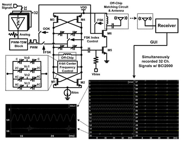
Neural signal-flow diagram, emphasizing the VCO architecture and on-chip class-AB PA, which reduces the effects of loading on the VCO. Inset: Wirelessly recorded 32ch waveforms when the WINeR-6 ASIC is inductively powered.
Figure 6.4.4 shows the power-transmission circuit. The primary coil (L1), whose geometry has been optimized for fP =13.56MHz [8], is driven by a 1W class-C PA, which is driven by a commercial RFID reader (MLX90121). On the receiver side, we have an off-chip L2C2 tank circuit tuned at fP, followed by a full-wave active rectifier and 3V LDO, both of which are integrated on WINeR-6. This rectifier provides a measured power conversion efficiency (PCE) of 80.2% at 13.56MHz utilizing a pair of offset-controlled high-speed comparators that compare VIN1,2 and VREC across P1 and P2 (W/L=2100/0.6), and drive their large gates. Four offset-control bits in each comparator (CTL0:3) adjust the rising and falling times such that the comparator delay is reduced to 0.75ns, and back currents are minimized. Changes in the coil coupling coefficient (k), resulting from animal movements, affect the rectifier output voltage (VREC), which is fed back to the Rx as one of the monitoring signals. This information is then used to control the PA supply voltage through an MSP430, a DAC, and a Darlington pair (Fig. 6.4.4) [9].
Figure 6.4.4.
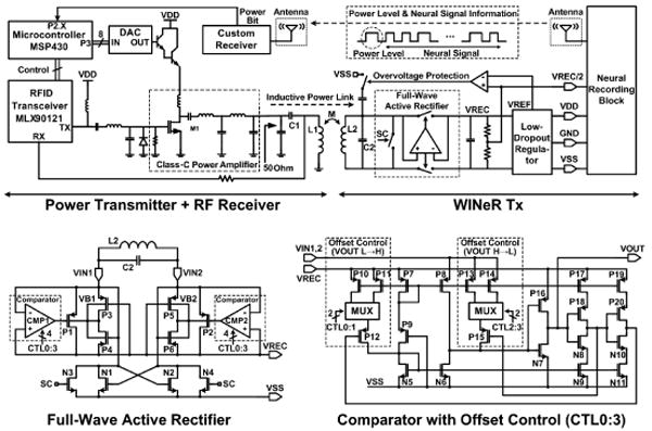
Inductive power flow diagram, showing the closed-loop power-control mechanism and high-efficiency full-wave active rectifier schematic [8].
WINeR-6 is fabricated in a 0.5μm 3M2P standard CMOS process and measures 4.9×3.3mm2 (Fig. 6.4.7). When all channels are active, it consumes 7mW from ±1.5V supplies in the FSK mode. With power scheduling (N=12) the power consumption drops to 5.8mW. With Tx and Rx antennas 0.5m apart, and L1 and L2 separated by 8cm, the system was bench-top tested using two function generators, whose outputs were divided to generate voltages below 1mV (Fig. 6.4.3 inset). Figure 6.4.5 shows the effect of power scheduling on the recorded waveforms at the LNA and PWM outputs, as well as power distribution among blocks. Figure 6.4.6 summarizes the specifications of the WINeR-6 ASIC and the experimental setup (Fig. 6.4.1 inset).
Figure 6.4.7.
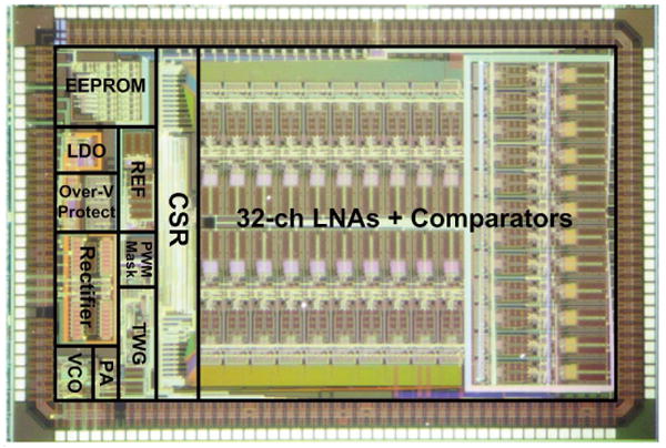
WINeR-6 4.9×3.3 mm2 die micrograph and floor plan.
Figure 6.4.5.
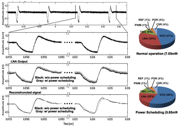
Measured waveforms from top: Original artificial spike waveform, recorded waveforms at the LNA output, sampled and pulse width demodulated waveforms. Power distribution chart among different blocks with and without power scheduling (N = 12).
Figure 6.4.6.
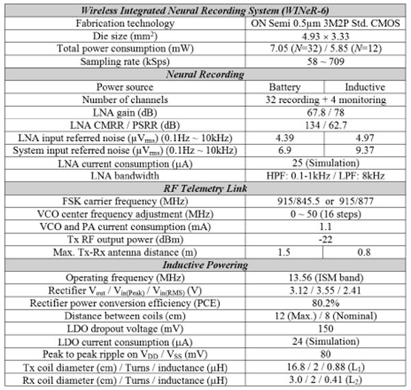
Summary of WINeR-6 system and test setup specifications.
References
- 1.Donoghue JP. Bridging the brain to the world: a perspective on neural interface systems. Neuron. 2008 Nov;60:511–521. doi: 10.1016/j.neuron.2008.10.037. [DOI] [PubMed] [Google Scholar]
- 2.Harrison RR, Kier RJ, Chestek CA, Gilja V, Nuyujukian P, Ryu S, Greger B, Solzbacher F, Shenoy KV. Wireless neural recording with single low-power integrated circuit. IEEE Trans Neural Syst Rehab Eng. 2009 Aug;17(4):322–329. doi: 10.1109/TNSRE.2009.2023298. [DOI] [PMC free article] [PubMed] [Google Scholar]
- 3.Avestruz A, Santa W, Carlson D, Jensen R, Stanslaski S, Helfenstine A, Denison T. A 5 μW/channel spectral analysis IC for chronic bidirectional brain–machine interfaces. IEEE Journal of Solid-State Circuits. 2008 Dec;43(12):3006–3024. [Google Scholar]
- 4.Plexon Inc. Multichannel Acquisition Processor. [Online], Available: http://www.plexon.com/products/map.html.
- 5.Chae MS, Yang Z, Yuce MR, Hoang L, Liu W. A 128-channel 6 mW wireless neural recording IC with spike feature extraction and UWB transmitter. IEEE Trans on Neural Sys Rehab Eng. 2009 Aug;17(4):312–321. doi: 10.1109/TNSRE.2009.2021607. [DOI] [PubMed] [Google Scholar]
- 6.Yin M, Ghovanloo M. A flexible 32-channel simultaneous wireless neural recording system with adjustable resolution. Digest of technical papers IEEE Intl Solid State Cir Conf. 2009 Feb;:432–433. [Google Scholar]
- 7.Rizk M, Bossetti CA, Jochum TA, Callender SH, Nicolelis MAL, Turner DA, Wolf PD. A fully implantable 96-channel neural data acquisition system. J Neural Eng. 2009 Apr;6(2) doi: 10.1088/1741-2560/6/2/026002. art. 026002. [DOI] [PMC free article] [PubMed] [Google Scholar]
- 8.Jow U, Ghovanloo M. Design and optimization of printed spiral coils for efficient transcutaneous inductive power transmission. IEEE Trans on Biomed Circuits and Systems. 2007 Sep;1(3):193–202. doi: 10.1109/TBCAS.2007.913130. [DOI] [PubMed] [Google Scholar]
- 9.Kiani M, Ghovanloo M. A closed loop wireless power transmission system using a commercial RFID transceiver for biomedical applications. IEEE 31st Eng in Med and Biol Conf; Sep, 2009. pp. 3841–3844. [DOI] [PMC free article] [PubMed] [Google Scholar]