Summary
A minimally invasive electrical recording and stimulating technique capable of simultaneously monitoring the activity of a significant number (e.g., 103 to 104) of neurons is an absolute prerequisite in developing an effective brain–machine interface. Although there are many excellent methodologies for recording single or multiple neurons, there has been no methodology for accessing large numbers of cells in a behaving experimental animal or human individual. Brain vascular parenchyma is a promising candidate for addressing this problem. It has been proposed [1, 2] that a multitude of nanowire electrodes introduced into the central nervous system through the vascular system to address any brain area may be a possible solution. In this study we implement a design for such microcatheter for ex vivo experiments. Using Wollaston platinum wire, we design a submicron-scale electrode and develop a fabrication method. We then evaluate the mechanical properties of the electrode in a flow when passing through the intricacies of the capillary bed in ex vivo Xenopus laevis experiments. Furthermore, we demonstrate the feasibility of intravascular recording in the spinal cord of Xenopus laevis.
Keywords: brain, computer interface, neural interface, vessel, catheter, Wollaston wire
1. Introduction
The brain–machine interface (BMI) or brain–computer interface (BCI) has been viewed primarily in terms of offering potential new therapies capable of restoring motor control in profoundly disabled patients, particularly those suffering from devastating conditions such as amyotrophic lateral sclerosis (ALS), spinal cord injury, stroke, and cerebral palsy (3, 4). BMI or BCI extracts the patient's intentions via neural activity and provides them with a new nonmuscular channel to control various devices. Today's BMI/BCI may be categorized as noninvasive techniques such as electroencephalography (EEG), magnetoencephalography (MEG), and functional magnetic resonance imaging (fMRI), and invasive techniques that implement direct cortical recordings with multielectrode arrays and electrocorticogram (ECoG) (4–12); such approaches have both advantages and disadvantages. Noninvasive recording methods such as an EEG interface record only neuronal activity from superficial brain areas with low spatial resolution. Empirically, the amount of information obtained with the EEG is limited to about 25 bits/min [4]. While MEG and fMRI are capable of recording more information, they require larger, more expensive instruments. On the other hand, the latest invasive methods can obtain about 7 bits/s, a roughly 10- to 100-fold increase; however, this requires craniotomy [9].
We are addressing the possibility of intravascular neural recording or stimulation as a neural interface that does not require craniotomy: that is, it is less invasive, yet can obtain large amounts of information [1, 2]. In this method, a statistically significant number (e.g., ultimately 103 to 104) of nanometer-scale electrodes are introduced through the capillary system. A catheter is used to deliver the electrodes into a deep brain area from a brachial or femoral artery. Such catheterization is an established surgical procedure for treatment of brain vasculature disorders.
In the investigation reported here we developed a prototype and evaluated its capabilities as an intravascular neural interface. Specifically, we developed an intravascular nanowire electrode that could be used as a probe for the interface. First, the method of fabrication of the electrode, including a nanowire manipulation method, was developed. Next, the fluid-dynamics characteristics of the nanowire needed to reach capillary were evaluated. Finally, the electrical properties of the electrodes were measured and neural activity was recorded from the central nervous system intravascularly.
2. Design of Nanowire Electrodes
Figure 1A shows a schematic diagram of the intravascular neural interface. To introduce probes into a blood vessel, we used the microcatheter illustrated in Fig. 1B (i). The microcatheter consists of a polyimide tube with a diameter of 90 to 300 μm depending on the diameter of the blood vessel of interest. The tube is connected to a T-shape connector, one end of which is used for saline input and the other for connection to an amplifier. Figure 1B (ii) shows the nanowire electrode. The electrode is introduced from the end of the microcatheter opposite to the T-shape connector and each tip is carried into the deep vasculature of the brain by the bloodstream. The wire is insulated with polymer and the tip of the electrode is electroplated with ϕ10 μm platinum black to reduce the electrode impedance. Since the required electrical properties of the nanowire electrode can be achieved by electroplating with platinum black, here we consider the mechanical properties of the nanowire electrode.
Fig. 1.
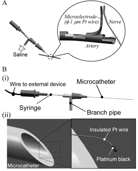
Schema of intravascular neural interface.
(A) A saline flow from a branch pipe introduces nanowires into an artery and the blood flow carries nanowires to a capillary close to a nerve. (B) (i) A microcatheter is made of polyimide tube with a 90 to 300-μm diameter. In the microcatheter, each nanowire has a wire connection extending through the branch pipe and syringe to external devices. (ii) The nanowire has a platinum black tip as an electrode interface and a polymer insulation layer along the entire wire.
Within a blood vessel, the nanowire electrode is carried by the blood flow. This force can be decomposed into two components, one parallel and the other perpendicular to the axis of the wire center. When the wire is carried by a fluid quasi-statically with time, the force parallel to the center axis acts as a tensile force in the wire and the force perpendicular to the center axis acts as the moment. Even in tortuous blood vessels, blood flow follows stream lines along the vessel, and so does the wire. Therefore, the blood flow keeps generating the moment in the wire and forces the wire to follow along the stream line. In this situation, the wire must be flexible enough to advance.
The flexural rigidity of the wire is described as the product of the Young's modulus E and the second moment of the area with respect to the center axis of the wire Iz, that is, EIz. When we define the diameter of the wire as dw, Iz is
| (1) |
Thus, the flexural rigidity of the wire is proportional to the fourth power of dw. The contribution of the insulation layer to the flexural rigidity is small compared to that of the wire itself and so can be ignored. Considering that in the vicinity of the electrode tip, the wire may be viewed as a beam of length l and a concentrated load Fd located at the tip of the electrode, the moment M acting on the beam and the radius of curvature ρ can be described as
| (2) |
| (3) |
Next, for simplicity, the platinum black on the tip of the electrode is assumed to be a sphere of diameter Dp. Taking the relative velocity between the electrode tip and the working fluid as Ur, the density of the fluid as ρf, and the coefficient of viscosity as μ, we can express the Reynolds number Re as
| (4) |
where Ur = 1 cm/s, Dp = 5 mm, ρf = 1 × 10³ kg/m3, μ = 1 × 10⁻³ Pa-s, Re = 5 × 10⁻². The value for water is used for the coefficient of viscosity. Since Re < 1 indicates laminar flow, by using the Stokes approximation equation, the force acting on the tip of the electrode Fd is described and estimated as
| (5) |
so that Fd = 4.7 × 10⁻¹⁰ N. The force of the blood flow, acting directly on the wire, is proportional to the surface area of the wire. However, when the wire diameter is sufficiently smaller than the electrode tip diameter, the force on the wire is not dominant. Therefore, since we consider only the behavior of the wire close to the tip, we ignore the force acting on the wire.
We now consider a platinum (Pt) wire. The Young's modulus E of Pt is 168 GPa. In order to obtain a radius of curvature ρ of about 10 μm with Fd, dw must be 0.3 μm according to Eq. (3). If the working fluid is blood, the viscosity coefficient μ is about 0.45 Pa-s, 450 times that for water. In this case, using the same calculation as for water, dw for ρ ≈ 10 μm is 1.3 μm. However, in this case, the Reynolds number, Re = 23, is too high, and the flow will not be laminar; thus, Fd is smaller than the estimate given by Eq. (5), and consequently ρ is slightly larger than the estimate given by Eq. (3).
Taking these considerations together, we employ platinum Wollaston wires with diameters ϕ1 μm and ϕ0.65 μm (Nilaco Corp.). Their second moments of area are 0.79 and 0.13 μm4, respectively, and their flexural rigidities are 1.32 × 10⁻²³ and 2.21 × 10⁻²⁴ N-m2. Under these conditions, the estimated radii of curvature ρ are 1750 and 312 μm for water, and 4 and 0.7 μm for blood.
3. Prototyping of Nanowire Electrode
Figure 2 shows the fabrication process of the nanowire electrode. This process comprises (A) preparation, (B) etching, (C) insulation, and (D) platinization. Because submicron Pt wire is fragile, all processes require proper manipulation, as described in Fig. 2. First, a special chamber equipped with protection against air currents and with heater functions was developed. Second, to prevent the platinum wire from adhering to dielectric materials as a result of static electricity it was held by using the surface tension of a droplet controlled by syringes during etching and platinization. Third, during insulation, the Pt wire was held in a laminar flow generated by vacuum from a ϕ0.4 mm tube.
Fig. 2.
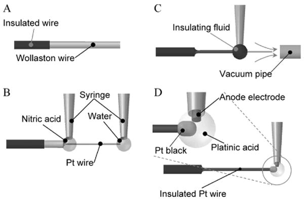
Fabrication of the nanowire electrode.
(A) Preparation. A tip of a Wollaston wire, i.e., a submicron Pt wire covered with Ag 40 μm in thickness, was insulated. The wire tip of 1 mm was left uninsulated for further processing. (B) Etching. The Ag-coated Pt nanowire was dipped in a drop of nitric acid, and the Ag topcoat was removed to expose the Pt wire. During this process a drop of water held the tip of the wire to keep the wire straight. (C) Insulation. The Pt wire was dipped in a drop of insulating fluid, and the drop moved toward the wire tip. The insulation fluid was baked in a laminar airflow holding the wire. (D) Platinization. A drop of platinic acid was applied to the wire tip to plate it with platinum black.
During preparation, a micro catheter system incorporating a Pt Wollaston wire protected by a silver layer was assembled. Before assembly, the wire was insulated on the silver layer except for the portion that would be exposed. During etching, the silver cover was dissolved by nitric acid and the thin Pt wire was exposed. During insulation, the Pt wire was dipped into a polyester resin solution (Cashew Co., Ltd., Cashew Strone Paint) and baked at 100 °C. This insulation process was repeated three times. During platinization, the tip of the Pt wire was immersed in a platinum (IV) ion plating solution (an aqueous solution of chloroplatinic acid 3.3% and lead acetate 3.3 × 10⁻²%) and electroplated at a voltage of 1 V while reversing polarities every 1 s for a total of 4 s.
Figure 3 shows the microcatheter system and the tip of the nanowire electrode. The electrode prototype consists of a 1-cm-long nanowire with diameter ϕ5 μm and a 30-μm-long platinum black section on the wire tip. The thickness of the insulation layer is about 100 nm.
Fig. 3.
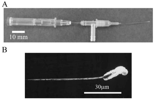
End product.
(A) Microcatheter. (B) Magnified view of nanowire under scanning electron microscope.
4. Evaluation
4.1 Evaluation method
A. Evaluation of mechanical properties of the nanowire
Using a fine channel as shown in Fig. 4, we measured the flexibility of the nanowire. In the channel, we used pouch film (Kokuyo S&T Corp., MSP-F70100). The width and depth of the channel were 500 and 100 μm, respectively. Using a micro syringe pump (KD Scientific Inc., IC3210), a constant flow of saline solution (0.9 M NaCl) was introduced into the channel so that the nanowire was pushed perpendicularly by the flow. Under these conditions, we measured the flexibility of the wire in terms of its radius of curvature. In this experiment, the working fluid could be approximately regarded as in laminar flow. The flow speed was calibrated with ϕ3 μm beads (Technochemical corp., Polybead® Polystyrene Microspheres). The test flow speeds were 0.1, 1, and 10 cm/s. The Pt wire diameters tested were 0.65 and 1 μm, and for both wires the length exposed to the flow pushing the wire was 300 μm. The temperature of the water was 17 °C and the viscosity at this temperature was 1.1 mPa/s.
Fig. 4.
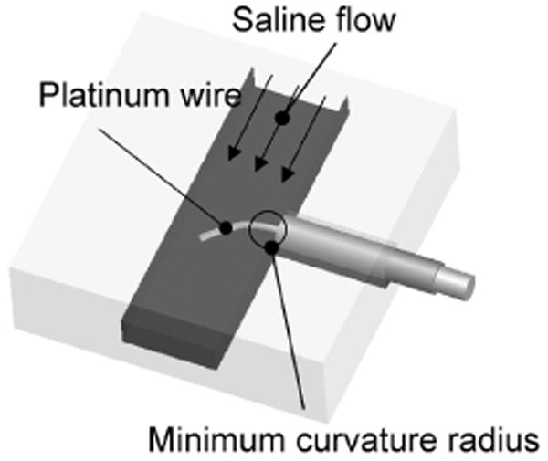
Experimental setup for assessment of wire flexibility.
A platinum wire is placed perpendicularly to a saline flow. The minimum radius of curvature represents the wire flexibility.
The movement of the electrode in a blood vessel was measured to evaluate the ex vivo mechanical properties of the prototype nanowire electrode. A segment of intestine was removed from Xenopus laevis, placed in a Petri dish, and superfused with saline. A microcatheter was inserted into a vessel and a nanowire electrode was introduced using saline perfusion. We observed the movement of ϕ1 μm and ϕ10 μm wire electrodes.
B. Evaluation of electrical properties of the nanowire electrode
The electrical properties of the prototype nanowire electrode as a neural interface were first evaluated. One-centimeter wires were immersed in saline solution and their impedance was measured at 1 kHz with an LCR meter (Yokogawa Hewlett Packard, 4274A). The ground and reference electrodes were Ag/AgCl electrodes with a surface area of 0.3 cm2. In this measurement, to evaluate the insulation and electrode properties separately, the impedance was measured before and after platinization.
Next, the feasibility of recording neuronal activity was evaluated using the prototype nanowire electrode within a blood vessel. The spinal cord of Xenopus laevis was exposed and a ϕ1 μm nanowire electrode was inserted into the anterior spinal artery using a microcatheter. A constant current pulse delivered through a bipolar stimulation electrode placed on the spinal cord elicited action potentials. The elicited neural activity was recorded with the nanowire electrode. A silver electrode, placed on the surface of the spinal cord, was used to compare the recordings of neural signals with the intravascular nanowire electrode. The stimulating pulse width was 20 μs and the current was 0.1 to 0.5 mA.
4.2 Results
Figure 5A shows the movement of the nanowire in the micro channel. As shown in the picture, the radius of curvature of the wire varied with the wire diameter and the flow velocity in the channel. Figure 5B summarizes the experimental results and the relationship of the human blood vessel diameter and blood velocity. In this figure, the blood flow velocity in a ϕ50 μm arteriole is about 1 cm/s [14]. At this velocity, the minimum radii of curvature of ϕ1 and 0.65 μm nanowires were 800 and 50 μm, respectively. A blood vessel bending at a right angle with a diameter D is shown in Fig. 5B. When the minimum radius of curvature R of the nanowire is smaller than the diameter D, the nanowire can pass through the blood vessel in the flow. Therefore, the results suggest that we can introduce ϕ1 μm and ϕ0.65 μm Pt wires into blood vessels with minimum diameters of 0.8 and 0.1 mm, respectively. The ϕ0.8 mm and ϕ0.1 mm blood vessels correspond to human small arteries and arterioles, respectively.
Fig. 5.
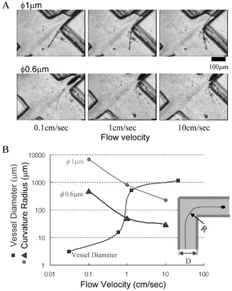
Assessment of wire flexibility.
(A) Behaviors of wires in a saline flow. (B) Curvature radius of platinum wire of ϕ1 μm and ϕ0.6 μm as a function of flow velocity. Blood vessel diameter as a function of flow velocity is also merged. As shown in inset, a wire with a radius of curvature R is expected to pass through a vessel with diameter D, when R < D.
Figure 6A (i) shows an experimental system using the intestinal blood vessels of Xenopus laevis. In Fig. 6A (ii), the intestinal blood vessels have a relatively simple vasculature with blood vessels ranging from ϕ100 μm to ϕ500 μm, offering an appropriate place to investigate the movement of nanowires. As a control, when we inserted a ϕ10 μm Pt wire into a vessel, the flexural rigidity was so high that the wire did not follow the bending blood vessel, but penetrated the blood vessel wall. Next, when we inserted a ϕ1 μm nanowire electrode, the saline solution flow with a velocity of about 5 mm/s carried the wire along the wall of a blood vessel branch with a radius of curvature of near 700 μm (Fig. 6B).
Fig. 6.
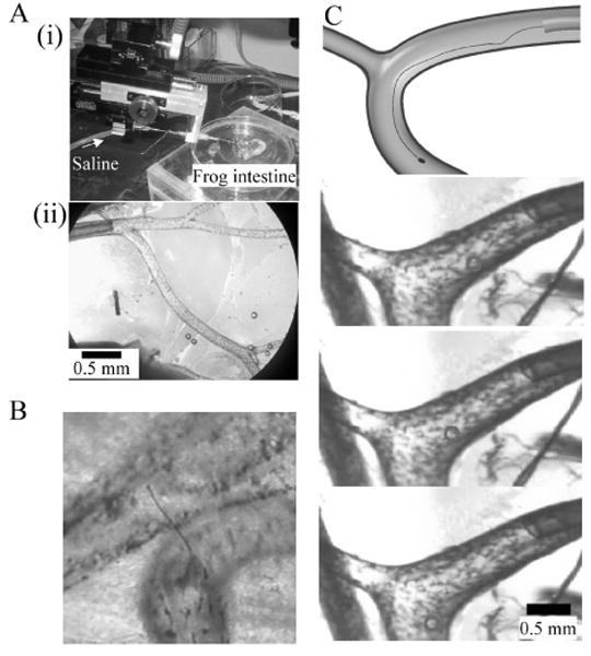
Assessment of nanowire electrode in frog mesentery artery.
(A) Experimental setup. (i) Microcatheter and frog intestine. (ii) Polyimide microcatheter (ϕ300 μm) is inserted into the mesentery artery. (B) Thick Pt wire of ϕ10 μm penetrates the blood vessel. (C) Fine Pt wire of ϕ1 μm is able to pass through the branch with a radius of curvature of about 700 μm in the 5 mm/s saline flow. The top panel shows a schematic diagram of the experiments. The bottom panels are time-series single video frames. Circle indicates location of electrode.
The impedance of the prototype nanowire electrode tip was over 10 MΩ, while the impedance of the insulated nanowire was about 100 kΩ. Before the insulation, the naked Pt wire had 0.5-kΩ impedance, which increased to 40 kΩ and 1 MΩ after the first and second treatments of the dipping and baking process, respectively. Thus, the impedance of the insulated wire increased with repeated dipping and baking. To assure insulation reliability, this process should be repeated three times or more.
Figure 7A shows an experimental setup using the spinal cord of Xenopus laevis. With a nanowire electrode inserted within a blood vessel, we recorded the neural signals shown in Fig. 7B (i). In this recording, after the stimulus artifact, positive and negative peaks at latencies of 0.75 and 1.50 ms were elicited. These neural responses were obtained with a current 5 times the threshold stimulus. Increasing the stimulus current increased the response amplitude with no change in the response latencies. Likewise, Fig. 7B (ii) shows similar neural signals that were recorded using the silver ball electrode placed on the spinal cord. The similarity of the recordings from the two electrodes suggests successful intravascular neural recordings with the nanowire electrode.
Fig. 7.
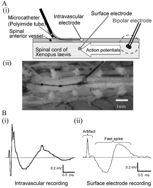
Intravascular neural recording.
(A) Experimental setup. (i) The intravascular nanowire electrode is inserted into the frog spinal anterior vessel through the microcatheter to record neural activities. Action potentials were elicited by bipolar electrode and conducted through the spinal cord. A surface electrode also recorded the activities for reference. (ii) Anterior side of spinal cord was exposed. A surface electrode is placed adjacent to the intravascular electrode. (B) Neural signals. Intravascular neural recording (i) and surface recording (ii) obtained comparable neural signals consisting of stimulus artifact and biphasic fast spikes.
5. Discussion
In the present study, we designed an intravascular neural interface consisting of a microcatheter and nanowire electrode. We examined the mechanical and electrical properties of the nanowire electrode and showed the feasibility of intravascular neural recording with the nanowire electrode.
The present set of experiments described the steps of nanoelectrode implantation requiring the incision of an artery followed by insertion of a microcatheter into the artery. However, smooth muscle in the artery contracted and shrank the incision site, making it difficult to insert the catheter into arterioles smaller than 100 μm in diameter. Considering this problem, the next generation of microcatheters should have an incision function. One of the design solutions can be, instead of a conventional syringe, a quartz capillary with a tip diameter of about 10 μm that is ground to be sufficiently sharp.
It is practically difficult to analyze and quantify the flexibility of a wire with a diameter on the submicrometer order in a blood vessel. The main reasons are:
The representative length of the wire is extremely short;
The fluid in a blood vessel is a multiphase flow including biological tissues; and
The flow boundary is a contractile blood wall.
Therefore, in this study, we implemented a simplified model to quantify the flexibility of the wire in fluid as an evaluation indicator and quantified the radius of curvature of the wire under conditions where the wire was bent maximally by the fluid flow. The radius of curvature estimated by Eq. (3) showed a good fit to our experimental results, suggesting that it is useful for the design of nanowire electrodes.
The arteries in the brain are categorized subdivided into the carotid artery, small arteries, arterioles, and capillaries. The spacings between small arteries, arterioles, and capillaries are about 1 mm, 0.1 mm, and a few tens of micrometers, respectively. We demonstrated that a ϕ1 μm nanowire electrode can approach an arteriole without damaging the blood vessel wall. Therefore, the results suggest that after x-ray angiography to visualize arterioles, it is feasible to insert a microcatheter into an artery with a diameter of a few millimeters and introduce ϕ1 μm Pt nanowire electrodes into the vasculature and record central nervous system activity within an arteriole network. Likewise, we can introduce ϕ0.65 μm nanowires into small artery networks.
This study shows that it is impossible to introduce the intravascular nanoelectrode into capillaries unless we decrease the flexural rigidity of the ϕ0.65 μm Pt wire nanowire electrodes to 1/10 to 1/100 of their present value. To achieve this goal, the diameter of the Pt wire must be 0.3 to 0.2 μm. Another promising solution is implementation of a conductive polymer [2], whose Young's modulus is 1/200 that of Pt.
On the other hand, instead of decreasing the flexural rigidity, another conceivable solution is to increase the fluid resistance of the electrode tip by enlarging the platinum black coating. However, in low Reynolds number flow such as that in arterioles, the contribution of the tip shape to the fluid force is small and the high friction of platinum black increases the probability of adhesion to a blood vessel wall. Thus, enlarging the platinum black tip to increase the fluid resistance is not a good solution. The diameter of the platinum black tip should be chosen with reference to the decrease in impedance needed to record neural activity.
The prototype nanowire electrode described here was able to record neural activities intravascularly, indicating that our design fulfilled the minimum required functions of a neural interface. However, the neural activity recorded in this experiment was a local spinal cord field potential, not the action potentials generated by individual neurons. Although we must verify that the prototype electrode can measure action potentials, it is highly likely, because the electrode had comparably low impedance with a conventional small metal electrode. However, for neural recordings in a volume conductor of brain parenchyma, low-frequency local field potentials decay on the order of 500 μm, while action potentials of high-frequency signals decay on the order of 50 μm. Therefore, for action potential recordings, it is highly likely that we must deliver the nanowire electrodes into an arteriole that is smaller than 50 μm in diameter or a capillary that is much smaller than an arteriole.
The intravascular neural interface system still has a number of future issues to be resolved. Among the most significant is determining the signal-to-noise ratio as a function of nanowire length, and thus the maximum vascular depth for the nanowire segment in the vascular bed. A second issue concerns the development of a technique to localize the tip of a nanowire electrode using MRI or CT. Third, we must determine the durability of wire electrodes and the stability of impedance for chronic implantation. Finally, the biocompatibility of implanted electrodes must be explored in terms of potential tissue reaction.
6. Conclusions
We have designed, developed, and evaluated an intravascular neural interface that records neuronal activities intravascularly. This interface consists of a microcatheter and nanowire electrode. The microcatheter introduces the electrode into a blood vessel with a saline flow. We used submicrometer Wollaston Pt wire as a material and manufactured a nanowire electrode. The electrode had an electroplated platinum black tip with a diameter of 2 μm and length of 10 μm. During the fabrication processes, it was mandatory to manipulate the extremely fragile submicrometer platinum wire by means of the surface tension of a droplet and a laminar air flow. We evaluated the flexibility of the nanowire electrode within a laminar flow in a small channel and found that ϕ1 and ϕ0.65 μm nanowire electrodes are applicable to the vasculature network of ϕ1 mm small arteries and ϕ0.1 mm arterioles, respectively. An ex vivo experiment showed that a ϕ1 μm nanowire electrode can be carried along the shape of blood vessel branches with a radius of curvature of 700 μm within ϕ400 μm blood vessels with saline flow at a velocity of 5 mm/s. The impedance of the ϕ1 μm nanowire electrodes was near 100 kΩ at the tip and over 10 MΩ in the insulated portion, fulfilling the required electrical properties as a neural interface. Finally we demonstrated that the prototype electrode could measure the neuronal activity in the spinal cord from the anterior spinal artery.
Biographies

Hirobumi Watanabe received his B.S. and M.S. degrees in mechanical engineering from the University of Tokyo in 2004 and 2006. He is now a graduate student at the Sackler Institute of Graduate Biomedical Sciences, New York University, where he is working in the field of neuroscience.

Hirokazu Takahashi received his B.S., M.S., and Ph.D. degrees in mechanical engineering from the University of Tokyo in 1998, 2000, and 2003. After working as a research associate in the Department of Engineering Synthesis, he joined the Department of Mechano-Informatics as an assistant professor in 2004. In 2006, he moved to the Research Center for Advanced Science and Technology of the same university. His research interests are in areas of biomedical engineering ranging from rehabilitation engineering for restoring lost functions to experimental neurophysiology for understanding fundamental brain functions.

Masayuki Nakao received his B.S. and M.S. degrees in mechanical engineering and Ph.D. degree from the University of Tokyo in 1981, 1983, and 1991. He was affiliated with Hitachi Metals, Ltd. from 1983 to 1989, and with HMT Technology Co., Ltd., Fremont, CA, from 1989 to 1992. He returned to Japan and joined the Department of Engineering Synthesis, University of Tokyo, as an associate professor in 1992. After working there at the Institute of Engineering Innovation, School of Engineering, as a professor, he is now affiliated with the Department of Engineering Synthesis. His research interests include knowledge management for creative design, nano- and micro-machining, and ultraprecision processing technology for industrial application.

Kerry Walton received her B.S. and M.S. degrees in physiology and anatomy from the University of California, Berkeley, and Ph.D. degree in neuroscience from New York University, where her thesis advisor was Dr. Rodolfo Llinás. She then worked as a postdoctoral fellow in Sir Bernard Katz's Biophysics Department at University College, London, subsequently returning to New York University, where she is on the faculty of the Department of Physiology and Neuroscience. Her research interests are in the field of neurophysiology of motor system function and CNS diseases.

Rodolfo R. Llinás has served as Chairman of the Department of Physiology and Neuroscience since 1976 and has been the Thomas and Suzanne Murphy Professor of Neuroscience at New York University School of Medicine since 1985. He has contributed over 500 publications to brain research, has been awarded eight honorary degrees, and is the recipient of numerous honors. The contributions of Dr. Llinás's research encompass many aspects of neuroscience, calcium channels and their functions in the central nervous system, the electrophysiology of the cerebellar neuronal circuit (in collaboration with J.C. Eccles), thalamocortical loop physiology in vitro, magnetoencephalography (MEG) recordings in humans, and chemical synaptic transmission in squid. He is a member of the National Academy of Sciences (USA) and the French Academy of Science.
References
- 1.Llinás R, Makarov V. Brain machine interface via a neurovascular approach. In: Roco M, Bainbridge WS, editors. Converging technologies for improving human performance. Springer; Academic Press; 2004. pp. 244–251. [Google Scholar]
- 2.Llinás R, Walton KD, Nakao M, Hunter IW, Anquetil PA. Neurovascular central nervous recording/stimulating system using nanotechnology probes. J Nanopart Res. 2005;7(2–3):111–121. [Google Scholar]
- 3.Lebedev MA, Nicolelis MA. Brain–machine interfaces: past, present and future. Trends Neurosci. 2006;29:536–546. doi: 10.1016/j.tins.2006.07.004. [DOI] [PubMed] [Google Scholar]
- 4.Wolpaw JR, Birbaumer N, McFarland DJ, Pfurtscheller G, Vaughan TM. Brain–computer interfaces for communication and control. Clin Neurophysiol. 2002;113:767–791. doi: 10.1016/s1388-2457(02)00057-3. [DOI] [PubMed] [Google Scholar]
- 5.Kauhanen L, Nykopp T, Sams M. Classification of single MEG trials related to left and right index finger movements. Clin Neurophysiol. 2006;117:430–439. doi: 10.1016/j.clinph.2005.10.024. [DOI] [PubMed] [Google Scholar]
- 6.Kamitani Y, Tong F. Decoding the visual and subjective contents of the human brain. Nature Neurosci. 2005;8:679–685. doi: 10.1038/nn1444. [DOI] [PMC free article] [PubMed] [Google Scholar]
- 7.Maynard EM, Nordhausen CT, Normann RA. The Utah Intracortical Electrode Array: a recording structure for potential brain–computer interfaces. Electroenceph Clin Neurophysiol. 1997;102:228–239. doi: 10.1016/s0013-4694(96)95176-0. [DOI] [PubMed] [Google Scholar]
- 8.Wessberg J, Stambaugh CR, Kralik JD, Beck PD, Laubach M, Chapin JK, Kim J, Biggs SJ, Srinivasan MA, Nicolelis MAL. Real-time prediction of hand trajectory by ensembles of cortical neurons in primates. Nature. 2000;408:361–365. doi: 10.1038/35042582. [DOI] [PubMed] [Google Scholar]
- 9.Santhanam G, Ryu SI, Yu BM, Afshar A, Shenoy KV. A high-performance brain–computer interface. Nature. 2006;442:195–198. doi: 10.1038/nature04968. [DOI] [PubMed] [Google Scholar]
- 10.Hochberg LR, Serruya MD, Friehs GM, Mukand JA, Saleh M, Caplan AH, Branner A, Chen D, Penn RD, Donoghue JP. Neuronal ensemble control of prosthetic devices by a human with tetraplegia. Nature. 2006;442:164–171. doi: 10.1038/nature04970. [DOI] [PubMed] [Google Scholar]
- 11.Levine SP, Huggins JE, BeMent SL, Kushwaha RK, Schuh LA, Rohde MM, Passaro EA, Ross DA, Elisevich KV, Smith BJ. A direct brain interface based on event-related potentials. IEEE Trans Rehab Eng. 2006;8:180–185. doi: 10.1109/86.847809. [DOI] [PubMed] [Google Scholar]
- 12.Mehring C, Rickert J, Vaadia E, de Oliveira SC, Aertsen A, Rotter S. Inference of hand movements from local field potentials in monkey motor cortex. Nature Neurosci. 2003;6:1253–1254. doi: 10.1038/nn1158. [DOI] [PubMed] [Google Scholar]
- 13.Nishino K. Flow field measurement of micro flows. Nagare. 2001;20:83–91. [Google Scholar]
- 14.Walter FB, Emile LB. Medical physiology. Saunders; 2003. p. 449. [Google Scholar]
- 15.Duvernoy HM, Delon S, Vannson JL. Cortical blood vessels of the human brain. Brain Res Bull. 1981;7:519–579. doi: 10.1016/0361-9230(81)90007-1. [DOI] [PubMed] [Google Scholar]
- 16.Okada S, Schraufnagel DE. Microvasculature of the olfactory organ in the Japanese monkey (Macaca fuscata fuscata) Microsc Microanal. 2002;8:159–169. doi: 10.1017/s1431927602020081. [DOI] [PubMed] [Google Scholar]
- 17.Tanaka E, Tanaka A, Sekka T, Shinozaki Y, Hyogo K, Umetani K, Mori H. Digitized cerebral synchrotron radiation angiography: Quantitative evaluation of the canine circle of Willis and its large and small branches. Am J Neuroradiol. 1999;20:801–806. [PMC free article] [PubMed] [Google Scholar]
- 18.Sarnelli A, Nemoz C, Elleaume H, Esteve F, Bertrand B, Bravin A. Quantitative analysis of synchrotron radiation intravenous angiographic images. Phys Med Biol. 2005;50:725–740. doi: 10.1088/0031-9155/50/4/011. [DOI] [PubMed] [Google Scholar]
- 19.Hoi Y, Meng H, Woodward SH, Bendok BR, Hanel RA, Guterman LR, Hopkins LN. Effects of arterial geometry on aneurysm growth: three-dimensional computational fluid dynamics study. J Neurosurg. 2004;101:676–681. doi: 10.3171/jns.2004.101.4.0676. [DOI] [PubMed] [Google Scholar]
- 20.Ruddy B, Watanabe H, Hunter I, Llinás R. Production of conducting polymer nanowires for use as intravascular neural recording electrodes. Technical Proceedings of the 2006 NSTI Nanotechnology Conference and Trade Show. 2:808–811. [Google Scholar]
- 21.Takahashi H, Suzurikawa J, Nakao M, Mase F, Kaga K. Easy-to-prepare assembly array of tungsten microelectrodes. IEEE Trans Biomed Eng. 2005;52:952–956. doi: 10.1109/TBME.2005.845224. [DOI] [PubMed] [Google Scholar]
- 22.Norena A, Eggermont JJ. Comparison between local field potentials and unit cluster activity in primary auditory cortex and anterior auditory field in the cat. Hear Res. 2002;166:202–213. doi: 10.1016/s0378-5955(02)00329-5. [DOI] [PubMed] [Google Scholar]
- 23.Gray CM, Maldonado PE, Wilson M, McNaughton B. Tetrodes markedly improve the reliability and yield of multiple single-unit isolation from multi-unit recordings in cat striate cortex. J Neurosci Method. 1995;63:43–54. doi: 10.1016/0165-0270(95)00085-2. [DOI] [PubMed] [Google Scholar]
- 24.Frien A, Eckhorn R. Functional coupling shows stronger stimulus dependency for fast oscillations than for low-frequency components in striate cortex of awake monkey. Eur J Neurosci. 2000;12:1466–1478. doi: 10.1046/j.1460-9568.2000.00026.x. [DOI] [PubMed] [Google Scholar]


