Abstract
The present paper proposes a model that describes the encapsulation of microbubble contrast agents by the linear Maxwell constitutive equation. The model also incorporates the translational motion of contrast agent microbubbles and takes into account radiation losses due to the compressibility of the surrounding liquid. To establish physical features of the proposed model, comparative analysis is performed between this model and two existing models, one of which treats the encapsulation as a viscoelastic solid following the Kelvin-Voigt constitutive equation and the other assumes that the encapsulating layer behaves as a viscous Newtonian fluid. Resonance frequencies, damping coefficients, and scattering cross sections for the three shell models are compared in the regime of linear oscillation. Translational displacements predicted by the three shell models are examined by numerically calculating the genera1, nonlinearized equations of motion for weakly nonlinear excitation. Analogous results for free bubbles are also presented as a basis to which calculations made for encapsulated bubbles can be related. It is shown that the Maxwell shell model possesses specific physical features that are unavailable in the two other models.
I. INTRODUCTION
Encapsulated microbubbles, known as ultrasound contrast agents, are effectively used in ultrasound medical diagnostics for increasing blood-tissue contrast during an ultrasonic examination. They are also employed in therapy as a vehicle for targeted drug delivery. Ultrasound contrast agents typically consist of a gas core surrounded by a shell of albumin, lipid, or a polymer material. A number of theoretical models have been proposed for different types of contrast agents.1–16 Most of them assume that the encapsulating layer behaves as a viscoelastic solid following the Kelvin-Voigt constitutive equation. There are also models that treat the encapsulation as a viscous Newtonian fluid.1,10,13,14 A viscoelastic solid appears to be an adequate model for polymer and albumin microbubble shells. For lipid shells, however, analysis of experimental data available in the literature suggests that a better approximation may be achieved by treating a lipid coating as a viscoelastic fluid. To substantiate this observation, let us analyze some experimental results obtained for lipid-shelled contrast agents.
An interesting observation as to resonance frequencies of lipid-shelled bubbles can be made from a paper by Dayton, Allen, and Ferrara.11 The paper presents experimental measurements of translational displacement for the contrast agent MP1950. MP1950 is a phospholipid-shelled microbubble with a decafluorobutane core. Figure 4 of this paper shows that at the excitation frequency 2.25 MHz the maximum displacement is observed for a bubble with a resting radius of about 1.5 µm. It is reasonable to assume that the maximum displacement is reached by a resonant bubble. Hence it turns out that a 1.5 µm radius lipid-shelled bubble has a resonance frequency of 2.25 MHz. For comparison, the linear damped resonance frequency of a free bubble of the same size is about 2.45 MHz. It is well known that a viscoelastic solid shell increases considerably the resonance frequency as compared with a free bubble.5 Therefore the fact that such a low resonance frequency is observed experimentally for lipid-shelled bubbles appears strange if the lipid shell is treated as a viscoelastic solid.
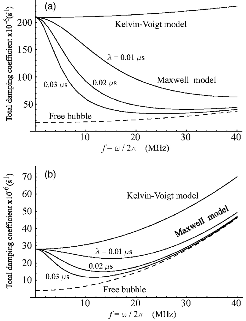
Figure 4.
Total damping coefficients as a function of frequency. (a) R20=0.5 µm; (b) R20=1.0 µm. The shell viscosity ηS=1.0 Pa s and the shell thickness RS=2 nm.
Another demonstrative work bringing to light the difference between lipid- and polymer-shelled contrast agents is that by Bloch et al.17 Figures 1(a) and 1(b) of their paper show the behavior of two contrast agents, BR14 and BG1135, in response to increasing acoustic forcing. BR14 is a perfluorobutane-filled microbubble, stabilized by a phospholipid shell a few nanometers thick. BG1135 is an air-filled microsphere with a 100-nm-thick polymer shell. Figure 1(b) shows that up to very high acoustic pressures, as long as the shell of the polymer-shelled agent BG1135 remains intact, its oscillation is very insignificant. This is a typical behavior of an elastic solid in response to a destructive action. The response of the lipid-shelled agent BR14 to increasing acoustic forcing, shown in Fig. 1(a), is much smoother, as if its shell were much more yielding. The destruction mechanisms of the two agents are also different. The polymer-shelled agent BG1135 appears to acquire a shell defect, allowing gas to stream out and form a new gas bubble, but leaving the original shell intact. Whereas the formation of a shell defect has never been observed for the lipid-shelled agent BR14. Instead, its shell fragmented along with its gas contents, forming a set of smaller bubbles. The impression arises that the breakdown of the lipid shell occurs as if its volume were insufficient to cover the entire bubble surface when the expansion of the bubble becomes large, in contrast to the polymer shell which breaks up in the traditional manner for elastic solid materials. Similar distinctions in destruction mechanisms were also observed between albumin-shelled agents and the lipid-shelled agent MP1950.18 They become explainable if we assume that the lipid shell has some fluid properties similar to the properties of Maxwell media. Indeed, a discontinuity in a solid shell, if once appeared, never vanishes completely, resulting in gas escape, while a discontinuity in a Maxwell material can close.
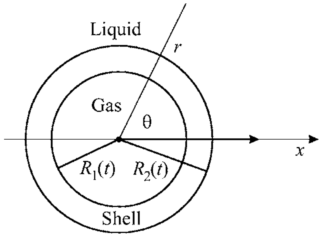
Figure 1.
Schematic sketch of an encapsulated bubble.
It is well known that the Maxwell constitutive equation has been proposed to describe complex materials that at fast effects behave as a solid, that is, they can deform, buckle, fold, etc., while at slow effects, they behave as a fluid. In particular, stresses in such media can relax in time, which is behavior impossible in traditional elastic solids. Among materials which are modeled by the Maxwell constitutive equation are such different substances as rosin, asphalt, glass, etc.19 In experimental papers on lipid shells,20–23 it is reported that these consist of condensed phase (polycrystalline or gel-like) domains surrounded by regions which are observed to have glassy or in some cases fluid-like properties. It is reasonable to assume that, when considered as a single whole, such a structure can have some properties of a Maxwell material. Note also that in biomedical ultrasound applications we deal with fast, MHz effects. Therefore, the buckling of lipid shells in response to compression at such high frequencies is not contradictory to the Maxwell model.
It should be noted that good agreement between experimental and simulated radius-time curves for lipid-shelled contrast agents has been reported recently by Marmottant et al.,15 even though they treated a lipid coating as a viscoelastic solid. A possible explanation for this result is as follows. The elastic regime is only a part of a compound model applied by Marmottant et al. This part appears not to be of decisive importance. The entire model of Marmottant et al. assumes that, when the bubble oscillates, the elastic regime holds only in a narrow range of radii. Outside this range, the dynamics of the bubble is governed by an ad hoc law for surface tension that is introduced by Marmottant et al. According to their law, if in the course of expansion the radius of the bubble exceeds a threshold value, the shell breaks up, the surface tension becomes equal to that for free bubbles, and the elastic term becomes zero. A second threshold value is set for compression and if the radius of the bubble goes below it, both the surface tension term and the elastic term vanish. As a result, the effect of the shell in these two cases reduces to the shell viscosity term alone. We suppose that bubbles in the simulation carried out by Marmottant et al. were mostly in this regime of lacking elasticity. Thus their results do not necessarily refute the arguments presented above.
The present paper proposes a model that approximates the rheological behavior of the lipid shell by the linear Maxwell constitutive equation. The model also takes into account the effect of translation on the radial motion of an encapsulated microbubble and acoustic radiation losses due to the compressibility of the surrounding liquid. For comparison, parallel with the Maxwell shell model, two existing models are considered. One of them treats the encapsulation as a viscoelastic solid following the Kelvin-Voigt constitutive equation and the other assumes that the encapsulating layer behaves as a viscous Newtonian fluid. To demonstrate physical differences between the three models, they are examined in the regime of linear oscillation.
II. THEORY
Let us consider a spherical encapsulated gas bubble surrounded by a liquid and undergoing radial oscillations in response to an imposed acoustic field. The geometry of the system is shown in Fig. 1. Assuming the surrounding liquid and the encapsulating layer to be incompressible, from the continuity equation it follows that both the velocity of the surrounding liquid and the velocity inside the bubble shell are subject to the equation
| (1) |
where υ stands for both of the above velocities. From this it follows further that
| (2) |
where υ(r, t) is the radial component of υ,R1(t) is the inner radius of the bubble shell, and the over-dot denotes the time derivative. If R1≤r≤R2, where R2(t) denotes the outer radius of the bubble, υ is the velocity inside the encapsulating layer; if r>R2, υ is the velocity of the surrounding liquid. Note also that the assumption of incompressible shell gives the following equations:
| (3) |
where R10 and R20 are, respectively, the inner and the outer radii of the bubble shell at rest. These equations will be used in further calculations.
Conservation of radial momentum yields24
| (4) |
where ρ is equal to ρS or ρL, ρS and ρL, are respectively, the equilibrium densities of the shell and the liquid, p is the pressure, and τrr is the stress deviator in the shell or the liquid.
The boundary conditions at the two interfaces are given by
| (5a) |
| (5b) |
where Pg(R1, t) is the pressure of the gas inside the bubble, σ1 and σ2 are the surface tension coefficients for the corresponding interfaces, and Pac(t) is the driving acoustic pressure at the location of the bubble. Integrating Eq. (4) over r from R1 to R2 using the parameters appropriate for the encapsulating layer and from R2 to ∞ using those appropriate for the surrounding liquid, assuming that the liquid pressure at infinity is equal to the hydrostatic pressure P0, and combining the resulting equation with Eqs. (5), one obtains
| (6) |
This equation is very convenient to test various rheological models for the shell material and the surrounding liquid. Testing can be done by just substituting respective rheological laws for . Equation (6) was used previously by Roy, Church, and Calabrese1 who treated the encapsulating shell as a viscous Newtonian fluid, and by Church5 who treated the encapsulating shell as a viscoelastic solid. In the present study, we will apply it to model a lipid coating by a viscoelastic fluid following the Maxwell constitutive equation.
Pursuing our calculation further and assuming that the behavior of the gas core is adiabatic, one has
| (7) |
where Pg0 is the equilibrium gas pressure in the bubble and γ is the ratio of specific heats. Assuming that the surrounding liquid is a viscous Newtonian fluid, is written as16
| (8) |
where ηL is the shear viscosity of the liquid. By using Eqs. (2) and (8), the second integral term in Eq. (6) is found to be
| (9) |
The behavior of the shell will be approximated by the linear Maxwell constitutive equation which can be expressed as19
| (10) |
where λ is the relaxation time and ηS is the shear viscosity of the shell. Equation (10) deserves further comment. The Maxwell model is known to be an interpolation equation for intermediate cases between an elastic solid and a viscous fluid. To demonstrate this, let us assume that and υ(r, t) depend on time as exp(iωt), where ω is the angular frequency of the driving field. Then Eq. (10) gives
where u is the radial displacement, du/dt=υ. For ωλ⪢1 (fast effects), this equation reduces to Hooke’s law for solids, , with the shear modulus μS=ηS /λ. While for ωλ⪡1 (slow effects), one obtains , which is Newton’s viscous law for fluids. These properties of the Maxwell model allow us to suppose that Eq. (10) may be an appropriate approximation for the specific structure of lipid shells as described in the Introduction.
By using Eq. (10), the first integral term in Eq. (6) can be worked out in the following way. Substituting Eq. (2) into Eq. (10), one has
| (11) |
Equation (11) suggests that can be written as
| (12) |
Substituting Eq. (12) into Eq. (11) shows that the function D(t) obeys the equation
| (13) |
Using Eqs. (12) and (3), the first integral term in Eq. (6) is calculated as
| (14) |
Substitution of Eqs. (7), (9), and (14) into Eq. (6) yields
| (15) |
where the function D(t) is calculated from Eq. (13).
Equation (15) can be modified to take account of the translation motion of the bubble and radiation losses due to the compressibility of the surrounding liquid. The modification can be performed by directly adopting necessary corrections from the equations of motion obtained in Ref. 16. The result is
| (16) |
where c is the speed of sound in the surrounding liquid, the function H is defined by
| (17) |
x(t) is the position of the center of the bubble in an inertial frame, and G denotes the right-hand side of Eq. (16). Note also that the acoustic pressure is now written as Pac(x, t), where the spatial argument x explicitly indicates that Pac(x, t) is the value of the driving pressure at the location of the bubble. The compressibility correction is given by the last term on the left-hand side of Eq. (16), while the first term on the right-hand side of Eq. (16) provides the coupling with the translational equation. This latter is given by
| (18) |
where mb is the mass of the bubble, the second term on the left-hand side of Eq. (18) is the added mass force, the first term on the right-hand side is the acoustic radiation force, and Fd is the viscous drag force which can be taken, for example, in the form of Oseen’s law24
| (19) |
Oseen’s formula is known to be more relevant than the Stokes law when the Reynolds number is close to unity. The Reynolds numbers in experiments on contrast agents are just on this order.
For D(0)=0, from Eq. (16) it follows that
| (20) |
It is also worth noting that in the general case ẋ in Eqs. (16) and (18) should be considered as the velocity of the bubble with respect to the velocity of the surrounding liquid. That is, if there is a stream in the bulk liquid, due to the propagation of the acoustic wave, acoustic streaming and so forth, ẋ should be replaced with ẋ−υex, where υex denotes the liquid velocity unrelated to the presence of the bubble.
Thus, we have the set of three ordinary differential equations: radial Eq. (16), translational Eq. (18), and Eq. (13) for D(t). The set is supplemented with the first of Eqs. (3) and Eqs. (17), (19), and (20). The initial conditions can be specified by R1(0)=R10, R2(0)=R20, Ṙ1(0)=Ṙ2(0)=0, x(0)=x0, ẋ(0)=0, and D(0)=0. Simultaneous numerical solution of all these equations yields the time-varying radius of the bubble and its translational displacement.
For comparison, parallel with the Maxwell shell model, we will examine two other existing models that treat the encapsulation as a viscoelastic solid or a viscous Newtonian fluid. For the first of them, which assumes that the shell material follows the Kelvin-Voigt constitutive equation,
| (21) |
with u the radial displacement in the shell and μS the shear modulus of the shell, the radial equation takes the form5,16
| (22) |
where the equilibrium gas pressure in the bubble, , is now given by
| (23) |
The function H in Eq. (22) is defined by Eq. (17) as before but G in Eq. (17) is now the right-hand side of Eq. (22), not Eq. (16). R1e denotes the unstrained equilibrium position of the gas-shell interface and is given by16
| (24) |
For the viscous shell model, which assumes that the shell behaves as a viscous Newtonian fluid, one has1
| (25) |
where H is calculated from Eq. (17) with G being the right-hand side of Eq. (25).
The translational equation for the Kelvin-Voigt and viscous models remains the same as defined by Eq. (18).
III. LINEAR ANALYSIS
In this section, we will compare predictions of the three shell models in the regime of linear oscillation. The purpose of this analysis is to reveal physical differences between the models which result from the fact that the models are based on different rheological laws.
Let us assume that the incident field is weak so the amplitude of the radial oscillation is small. Then one can write
| (26) |
where it is assumed that |ξ| ⪡R10. Linearizing Eq. (13) with respect to ξ, one has
| (27) |
Assuming that the acoustic pressure can be expressed as Pac(t)=Pa exp(iωt), where Pa is the pressure amplitude and ω is the angular driving frequency, solution to Eq. (27) can be represented as
| (28) |
Substituting Eq. (28) into Eq. (27), one finds
| (29) |
For the Maxwell shell model, linearizing Eq. (16) by means of Eqs. (26) and using Eqs. (28) and (29) one obtains
| (30) |
where
| (31) |
| (32) |
| (33) |
| (34) |
| (35) |
| (36) |
| (37) |
It is somewhat unusual that in Eq. (30) the resonance frequency ω0M is a function of the driving frequency ω. Of prime interest is, however, not ω0M because it is common knowledge that the real resonance frequency of a system with damping differs from the undamped resonance frequency ω0M.25 To evaluate the damped (real) resonance frequency of Eq. (30), let us consider a solution to this equation,
| (38) |
where
| (39) |
| (40) |
| (41) |
The resonance response of the bubble corresponds to a maximum of the function Q(ω). One can see that Q(ω) is a fairly complicated function of ω. Therefore it will be examined numerically below. The damped resonance frequency of the Maxwell shell model will be denoted by ωdM below.
For the Kelvin-Voigt shell model, expressions for the undamped and damped resonance frequencies as well as damping terms were obtained in Ref. 16:
| (42) |
| (43) |
| (44) |
Note that the equations for α, δr, and δηL remain the same. The quantity ω0KV denotes the undamped resonance frequency. The damped resonance frequency is given by
| (45) |
where β=δr/ω2=ρLR10/(αcρS).
The undamped resonance frequency, ω0V, and damping constants for the viscous shell model can be obtained from Eqs. (32)–(37) by setting λ=0. The result is
| (46) |
To obtain the damped resonance frequency of the viscous shell model, one needs only to replace ω0KV in Eq. (45) with ω0V=ω0 since ,
| (47) |
In the process of comparing the shell models we will also refer to a free bubble. The undamped resonance frequency, ω0f, and damping constants for a free bubble can be immediately obtained from Eqs. (31)–(37) by setting R10=R20. This yields
| (48) |
| (49) |
where R0 is the equilibrium radius of a free bubble and σf is the surface tension at the gas-liquid interface. It is easy to verify that these equations are identical to those obtained by Prosperetti.26 Setting R10=R20 in Eq. (45) gives the damped resonance frequency of a free bubble as
| (50) |
with βf=R0/c.
Finally, we need to estimate the order of the shell parameters which will be used in further calculations. The dynamics of lipid-shelled bubbles was modeled previously by Marmottant et al.15 Neglecting the liquid compressibility correction, their model takes the form
| (51) |
where R denotes the instantaneous outer radius of an encapsulated bubble, R0 is the radius of the bubble at rest, κs is the dilatational viscosity, and χ is the elastic compression modulus. Equation (51) belongs to the type of the so-called zero-thickness encapsulation models. It is reported by Marmottant et al. that good agreement with experimental data is reached for κs=7.2×10⁻⁹ N s/m and χ=1 N/m. Now, if we neglect the compressibility correction and the translational term in Eq. (22) and assume that the shell thickness RS=R2−R1 is much smaller than R1 and R2, Eq. (22) reduces to an equation of the above-named type as well:
| (52) |
where σ=σ1+σ2. One can see that Eqs. (51) and (52) are in agreement provided that
| (53) |
Using these relations, one finds that for RS=2 nm, ηS=1.2 Pa s and μS=166.7 MPa. From what is said after Eq. (10) it follows that the order of the relaxation time λ corresponding to these values of ηS and μS can be estimated as λ=ηS/μS≈0.007 μs. These values will be used as a guide in further calculations.
The values of the other physical parameters used in our calculations are p0=101.3 kPa, ρL=1000 kg/m3, ηL=0.001 Pa s, c=1500 m/s, γ=1.07, σf=0.072 N/m, ρS=1100 kg/m3, and σ2=0.051 N/m. The parameters for the surrounding liquid correspond to water. The value of σ2 was chosen following Morgan et al.9 For simplicity, we set σ1=0. We believe this point is not principal in the case of lipid encapsulation and cannot noticeably distort results. It is apparent that for a very thin coating, as with lipid shells, the net effect of the two terms 2σ1/R1 and 2σ2/R2 can be approximated with a good accuracy by the single term 2σ/R2 with σ=σ1+σ2, i.e., as if σ1 were equal to zero while σ2 were equal to the sum σ1+σ2. Note that Marmottant et al.15 also offer considerations from which it follows that the surface tension at the gas-lipid interface can be taken to be zero.
A. Resonance frequencies
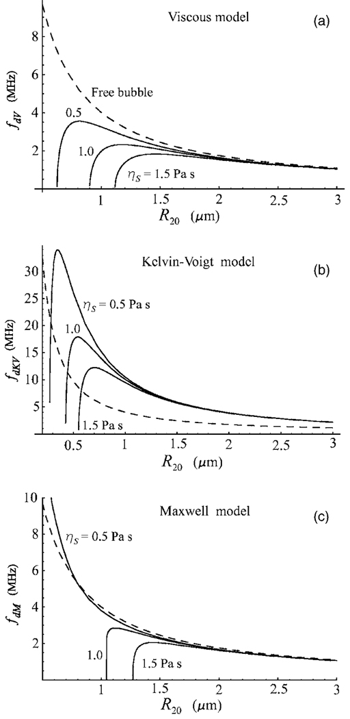
Figure 2 shows the damped resonance frequency of an encapsulated bubble as a function of equilibrium radius for the three shell models at three values of the shell viscosity, ηS=0.5, 1.0, and 1.5 Pa s. The values of the other shell parameters used in these calculations are RS=2 nm, μS=166.7 MPa, and λ=0.02 μs. The range of bubble radii was chosen to correspond to the size of contrast agent microbubbles used in ultrasound medical applications. The dashed line represents the damped resonance frequency of a free bubble, fdf=ωdf/2π, calculated from Eq. (50). Figure 2(a) demonstrates a well-known fact that a viscous shell decreases the resonance frequency with respect to that of a free bubble and leads to the utter extinction of resonance response for small bubbles. On the contrary, a viscoelastic solid shell increases the resonance frequency relative to a free bubble, see Fig. 2(b). For small bubbles, however, the viscous damping inside the shell again results in the absence of resonance. The Maxwell model, Fig. 2(c), shows a specific behavior that is not observed in the two previous cases, namely, if the shell viscosity is not too high, the resonance frequency of a bubble with a viscoelastic fluid shell can be both lower and higher than that of a free bubble. In other words, as could be expected from what was said following Eq. (10), the Maxwell shell can behave in both the viscous and elastic manner. The damped resonance frequency of a bubble with a Maxwell shell, fdM=ωdM/2π, becomes higher than that of a free bubble, fdf, when the elastic properties of the shell begin to predominate over its viscous properties. This takes place when ωdMλ is large enough. It is found that it is not necessary for this quantity to be large compared to unity. For example, from Fig. 2(c) it follows that fdM becomes higher than fdf at ωdMλ≈0.68, which corresponds to the resonant radius R20=0.79 µm at λ=0.02 μs and ηS=0.5 Pa s. With increasing λ, which means increasing elasticity of the shell, the critical value of R20 increases as well. For example, for λ=0.025 μs and the same shell viscosity, the critical radius R20=0.95 µm. Note also that if fdM>fdf and the Maxwell model goes into the elastic regime, the resonance response persists for arbitrarily small bubbles as the Maxwell model reduces to Hooke’s law which ignores viscous damping. In regard to the ηS=0.5 Pa s curve in Fig. 2(c), it is also interesting to note that, despite the presence of the encapsulating shell, this curve remains very close to the resonance curve for free bubbles within a wide enough range of radii.
Figure 2.
Damped resonance frequency as a function of equilibrium bubble radius for three values of the shell viscosity ηS. (a) Viscous model, fdV=ωdV/2π; (b) Kelvin-Voigt model, fdKV=ωdKV/2π, μS=166.7 MPa; (c) Maxwell model, fdM=ωdM/2π, λ=0.02 μs. The shell thickness RS=2 nm. The dashed line shows the damped resonance frequency of a free bubble.
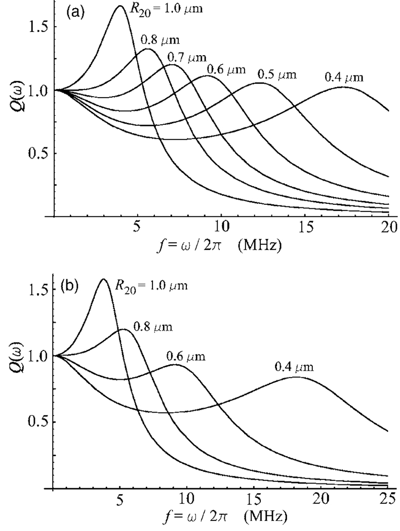
The form of the resonance function Q(ω) of the Maxwell shell model, Eq. (41), in the elastic regime is specific as well. The resonance functions of the two other models can be only of two types, either with a global resonance peak or, if the resonance response is suppressed by the shell viscosity, monotonically decreasing as the driving frequency increases. Figure 3 shows that the resonance function of the Maxwell model in the range of bubble sizes corresponding to the elastic regime can take the form of a curve with a local maximum. This effect gives rise to the resonance response for indefinitely small bubbles. However, the strength of the resonance oscillation of such bubbles can be smaller than the strength of their nonresonance oscillation at a lower driving frequency, see the R20=0.4 µm curve in Fig. 3(b).
Figure 3.
The resonance function Q(ω) of the Maxwell shell model for various values of the equilibrium radius R20. (a) λ=0.025 μs; (b) λ=0.02 μs. The shell viscosity ηS=0.5 Pa s and the shell thickness RS=2 nm.
B. Damping coefficients
For the Kelvin-Voigt and viscous models, the damping coefficients are identical, see Eq. (46). The difference with the Maxwell model is only in the shell viscosity term , cf. Eqs. (35) and (43). Due to the factor [1+(λω)2]−1, is always smaller than , the divergence increasing as frequency increases. This means that the total damping for a Maxwell shell is always smaller than that for the two other types of encapsulation. The totals of the damping constants of the shell models are shown in Fig. 4 as functions of frequency for equilibrium bubble radii of 0.5 µm, Fig. 4(a), and 1 µm, Fig. 4(b), assuming ηS=1.0 Pa s and RS=2 nm. The upper curve in both the parts of Fig. 4 corresponds to the Kelvin-Voigt and viscous models. The bottom (dashed) curve gives the total damping coefficient for a free bubble, δf, calculated from Eq. (48). The three intervening curves were obtained for the Maxwell model at three values of the relaxation time, λ=0.01, 0.02, and 0.03 μs. It is seen that the larger the relaxation time, the closer the Maxwell curve is to that for a free bubble. As with resonance frequencies, we again observe an interesting effect inherent in the Maxwell model, namely the damping of a bubble with a Maxwell shell can be fairly close to that for a free bubble.
Comparison of Figs. 4(a) and 4(b) shows that increasing the bubble size makes all the curves approach each other. This is an expected result since the relative contribution of the viscous damping decreases with increasing bubble size as follows from Eqs. (34), (35), (43), and (48). On the contrary, the relative contribution of the acoustic damping increases as is seen from Eq. (33). But the acoustic damping coefficient is the same for all the three shell models. Moreover, if the shell thickness is small as in our case, the result of Eq. (33) does not differ much from the acoustic damping for a free bubble, Eq. (48). As a consequence, the damping-frequency curves for all the shell models and the free bubble come closer together as the equilibrium bubble radius increases.
Both are linearly dependent on the shell viscosity ηS. Therefore variations in ηS cannot lead to qualitative changes in Fig. 4 and are not exemplified here. Note also that our analysis ignores the thermal damping. This neglect is justified for MHz frequencies and micron-sized bubbles which are used in ultrasound medical applications since the relative contribution of the thermal damping is negligible under such conditions.5,26
C. Scattering cross sections
The scattering cross section of a bubble is defined as
| (54) |
where Pa is the pressure amplitude of the incident acoustic wave and Ps is the pressure wave scattered by the bubble. In the case of linear oscillation, Ps can be written as
| (55) |
where ξ is defined by Eqs. (38)–(41), provided the expressions for the resonance frequency and the damping constant are changed to those needed for the shell model considered. Substituting Eq. (55) into Eq. (54), one finds
| (56) |
where, according to the model required, δ is δM, δKV, or δV, and ωm is ω0M, ω0KV, or ω0V, respectively. For a free bubble, one has
| (57) |
where R0=R20 in our calculations.
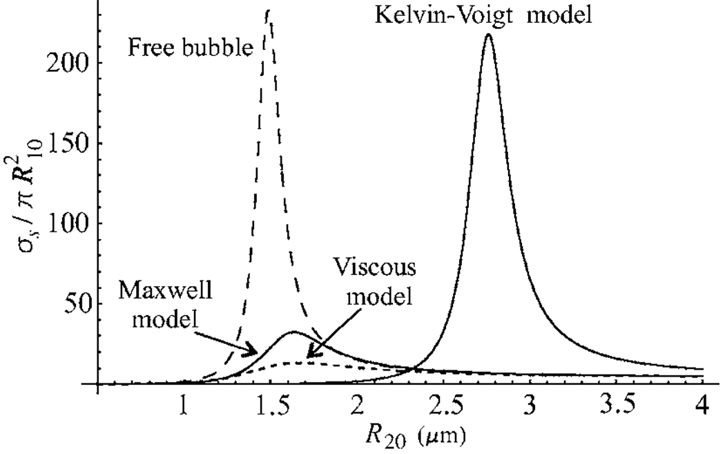
Calculated values for the linear scattering cross sections of the three shell models, normalized to the respective geometrical cross sections of bubbles, are given in Fig. 5 as a function of equilibrium bubble radius for a driving frequency of 2.5 MHz. The values of the shell parameters used in these calculations are RS=2 nm, ηS=1.0 Pa s, μS=166.7 MPa, and λ=0.05 μs. The scattering cross section for free bubbles is presented by the long-dashed line. It is seen that the Kelvin-Voigt model gives the vastly greater amplitude of the scattering cross section than the two other models. This occurs as the Kelvin-Voigt shell increases considerably the resonance radius of encapsulated bubbles, while the resonant scattering of larger bubbles is known to be of greater intensity. The resonance radii of bubbles with the Maxwell and viscous shells remain close to those for free bubbles, but unlike free bubbles, bubbles with the Maxwell and viscous shells undergo the additional damping due to the shell viscosity. As a result, the amplitudes of their scattering cross sections are much less than for free bubbles resonant at the same frequencies.
Figure 5.
Scattering cross sections as a function of equilibrium radius for the three shell models and free bubbles (long-dashed line) at a driving frequency of 2.5 MHz. The shell parameters are RS=2 nm, ηS=1.0 Pa s, μS=166.7 MPa, and λ=0.05 μs.
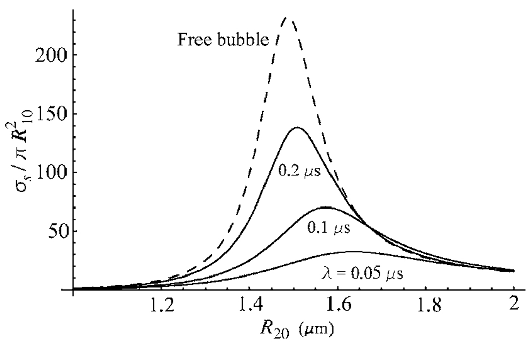
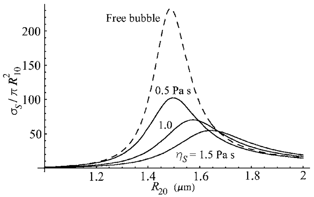
Figure 6 shows that increasing the relaxation time in the Maxwell model increases the amplitude of the scattering cross section, not giving rise, however, to an increase in the resonance radius of the encapsulated bubble. As one would expect, increasing the shell viscosity in the Maxwell model results in decreasing amplitude of the scattering cross section, see Fig. 7.
Figure 6.
Scattering cross sections as a function of equilibrium radius for the Maxwell shell model with λ=0.05, 0.1, and 0.2 μs, at a driving frequency of 2.5 MHz. The shell viscosity ηS=1.0 Pa s and the shell thickness RS=2 nm. The dashed line corresponds to free bubbles.
Figure 7.
Scattering cross sections as a function of equilibrium radius for the Maxwell shell model with ηS=0.5, 1.0, and 1.5 Pa s, at a driving frequency of 2.5 MHz. The relaxation time λ=0.1 μs and the shell thickness RS=2 nm. The dashed line corresponds to free bubbles.
IV. TRANSLATIONAL MOTION
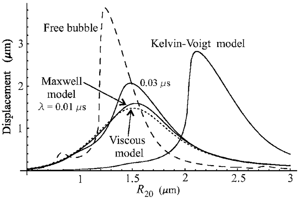
To compare predictions of the three shell models regarding the translational displacement of encapsulated bubbles, the values of the shell parameters were chosen as follows. The shell thickness and the shell viscosity were set equal to RS=2 nm and ηS=1.0 Pa s, respectively. The shear modulus μS responsible for the elastic properties of the Kelvin-Voigt model was set equal to μS=100 MPa. The relaxation time λ specifying the elastic properties of the Maxwell model was taken to be equal to λ=ηS/μS=0.01 μs. This choice allows one to reckon that the shell parameters of all the models are commensurable so that differences in the predictions of the models are due to qualitative rather than quantitative differences in their behavior. The values of the other physical parameters used in these calculations were the same as indicated after Eq. (53). It was assumed that bubbles were set in motion by a single 20-cycle acoustic pulse with a pressure amplitude of 100 kPa and a center frequency of 2.5 MHz. The translational displacement was fixed after the termination of the pulse. Simulations were carried out by numerically calculating Eqs. (16) and (18) for the Maxwell model, Eqs. (22) and (18) for the Kelvin-Voigt model, and Eqs. (25) and (18) for the viscous model. The translational displacement for free bubbles was calculated using the equations of motion presented in Ref. 27. The results obtained are given in Fig. 8. One can see that the peak displacement given by the Kelvin-Voigt model exceeds those predicted by the other two shell models. Since the Kelvin-Voigt shell increases the resonance frequency of an encapsulated bubble with respect to that of a free bubble of the same size, the bubble radius corresponding to the Kelvin-Voigt peak displacement is considerably larger than those for the other two shell models and free bubbles. It is interesting to note that the Maxwell model allows one to increase the value of the peak displacement by increasing the relaxation time, not changing the value of the shell viscosity and not increasing the value of the bubble radius corresponding to the peak displacement. This effect is illustrated in Fig. 8 by the upper Maxwell curve obtained at λ=0.03 μs, all the other parameters being the same.
Figure 8.
Translational displacement as a function of equilibrium bubble radius. Bubbles are insonified with a 20 cycle, 2.5 MHz, 100 kPa acoustic pulse. The displacement is fixed after the termination of the pulse. The shell parameters are RS=2 nm, ηS=1.0 Pa s, and μS=100 MPa. The curves for the Maxwell model are calculated at λ=0.01 and 0.03 μs.
V. CONCLUSIONS
Experimental data show that lipid-shelled contrast agents have properties that distinguish them from albumin- and polymer-shelled agents. Among such properties are low resonance frequencies of lipid-shelled bubbles, different destruction mechanisms, and the specific structure of lipid monolayer coatings being a combination of condensed phase domains surrounded by fluid-like regions. These experimental observations suggest that a viscoelastic fluid may be a better approximation for lipid shells than a viscoelastic solid or a simple viscous fluid. Based on this hypothesis, a new theoretical model for a lipid-shelled bubble has been proposed. The model assumes that the rheological behavior of the lipid shell follows the linear Maxwell constitutive equation. The model also incorporates the translational motion of the bubble and radiation losses due to the compressibility of the surrounding liquid. To reveal physical features of the new model, comparative analysis has been performed between this model and two existing models. One of them treats the encapsulation as a viscoelastic solid following the Kelvin-Voigt constitutive equation, and the other assumes that the encapsulating layer behaves as a viscous Newtonian fluid. Comparison between the three shell models was carried out for resonance frequencies, damping coefficients, and scattering cross sections in the regime of linear oscillation. Numerical simulations on the translational dynamics were made for weakly nonlinear excitation by using the general, nonlinearized equations of motion. Analogous results for free bubbles were used as a common basis to which calculations made for encapsulated bubbles can be related. It has been shown that the new model possesses specific physical features that are unavailable in the two other models.
ACKNOWLEDGMENTS
A. A. D. wishes to acknowledge the financial support of the International Science and Technology Center (ISTC) under Contract No. B-1213. P. A. D. acknowledges support from NIH R21EB005325. The authors wish to thank Mark Borden and Katherine Ferrara for helpful discussions regarding lipid-coated microbubbles.
Footnotes
PACS number(s): 43.25.Yw, 43.35.Ei, 43.80.Qf, 43.80.Ev [CCC]
Contributor Information
Alexander A. Doinikov, Institute of Nuclear Problems, Belarus State University, 11 Bobruiskaya Street, Minsk 220050, Belarus.
Paul A. Dayton, Department of Biomedical Engineering, University of California, 451 East Health Sciences Dr., Davis, California 95616
References
- 1.Roy RA, Church CC, Calabrese A. Cavitation produced by short pulses of ultrasound. In: Hamilton MF, Blackstock DA, editors. Frontiers of Nonlinear Acoustics: Proceedings of 12th ISNA. London: Elsevier; 1990. pp. 476–481. [Google Scholar]
- 2.de Jong N, Hoff L, Skotland T, Bom N. Absorption and scatter of encapsulated gas filled microspheres: Theoretical consideration and some measurements. Ultrasonics. 1992;30:95–103. doi: 10.1016/0041-624x(92)90041-j. [DOI] [PubMed] [Google Scholar]
- 3.de Jong N, Hoff L. Ultrasound scattering of Albunex microspheres. Ultrasonics. 1993;31:175–181. doi: 10.1016/0041-624x(93)90004-j. [DOI] [PubMed] [Google Scholar]
- 4.de Jong N, Cornet R, Lancee CT. Higher harmonics of vibrating gas-filled microspheres. Part one: Simulations. Ultrasonics. 1994;32:447–453. [Google Scholar]
- 5.Church CC. The effect of an elastic solid surface layer on the radial pulsations of gas bubbles. J. Acoust. Soc. Am. 1995;97:1510–1521. [Google Scholar]
- 6.Ye Z. On sound scattering and attenuation of Albunex bubbles. J. Acoust. Soc. Am. 1996;100:2011–2028. [Google Scholar]
- 7.Frinking PJA, de Jong N. Acoustic modeling of shell-encapsulated gas bubbles. Ultrasound Med. Biol. 1998;24:523–533. doi: 10.1016/s0301-5629(98)00009-x. [DOI] [PubMed] [Google Scholar]
- 8.Hoff L, Sontum PC, Hovem JM. Oscillations of polymeric microbubbles: Effect of the encapsulating shell. J. Acoust. Soc. Am. 2000;107:2272–2280. doi: 10.1121/1.428557. [DOI] [PubMed] [Google Scholar]
- 9.Morgan KE, Allen JS, Dayton PA, Chomas JE, Klibanov AL, Ferrara KW. Experimental and theoretical evaluation of microbubble behavior: Effect of transmitted phase and bubble size. IEEE Trans. Ultrason. Ferroelectr. Freq. Control. 2000;47:1494–1509. doi: 10.1109/58.883539. [DOI] [PubMed] [Google Scholar]
- 10.Allen JS, May DJ, Ferrara KW. Dynamics of therapeutic ultrasound contrast agents. Ultrasound Med. Biol. 2002;28:805–816. doi: 10.1016/s0301-5629(02)00522-7. [DOI] [PubMed] [Google Scholar]
- 11.Dayton PA, Allen JS, Ferrara KW. The magnitude of radiation force on ultrasound contrast agents. J. Acoust. Soc. Am. 2002;112:2183–2192. doi: 10.1121/1.1509428. [DOI] [PubMed] [Google Scholar]
- 12.Khismatullin DB, Nadim A. Radial oscillations of encapsulated microbubbles in viscoelastic liquids. Phys. Fluids. 2002;14:3534–3557. [Google Scholar]
- 13.Chatterjee D, Sarkar K. A Newtonian rheological model for the interface of microbubble contrast agents. Ultrasound Med. Biol. 2003;29:1749–1757. doi: 10.1016/s0301-5629(03)01051-2. [DOI] [PubMed] [Google Scholar]
- 14.Sarkar K, Shi WT, Chatterjee D, Forsberg F. Characterization of ultrasound contrast microbubbles using in vitro experiments and viscous and viscoelastic interface models for encapsulation. J. Acoust. Soc. Am. 2005;118:539–550. doi: 10.1121/1.1923367. [DOI] [PubMed] [Google Scholar]
- 15.Marmottant P, van der Meer S, Emmer M, Versluis M, de Jong N, Hilgenfeldt S, Lohse D. A model for large amplitude oscillations of coated bubbles accounting for buckling and rupture. J. Acoust. Soc. Am. 2005;118:3499–3505. [Google Scholar]
- 16.Doinikov AA, Dayton PA. Spatio-temporal dynamics of an encapsulated gas bubble in an ultrasound field. J. Acoust. Soc. Am. 2006;120:661–669. doi: 10.1121/1.2215228. [DOI] [PMC free article] [PubMed] [Google Scholar]
- 17.Bloch SH, Wan M, Dayton PA, Ferrara KW. Optical observation of lipid- and polymer-shelled ultrasound microbubble contrast agents. Appl. Phys. Lett. 2004;84:631–633. [Google Scholar]
- 18.Dayton PA, Morgan KE, Klibanov AL, Brandenburger GH, Ferrara KW. Optical and acoustical observations of the effects of ultrasound on contrast agents. IEEE Trans. Ultrason. Ferroelectr. Freq. Control. 1999;46:220–232. doi: 10.1109/58.741536. [DOI] [PubMed] [Google Scholar]
- 19.Landau LD, Lifshitz EM. Theory of Elasticity. Oxford: Pergamon; 1986. [Google Scholar]
- 20.Borden MA, Longo ML. Dissolution behavior of lipid monolayer-coated, air-filled microbubbles: Effect of lipid hydrophobic chain length. Langmuir. 2002;18:9225–9233. [Google Scholar]
- 21.Kim DH, Costello MJ, Duncan PB, Needham D. Mechanical properties and microstructure of polycrystalline phospholipid monolayer shells: Novel solid microparticles. Langmuir. 2003;19:8455–8466. [Google Scholar]
- 22.Borden MA, Pu G, Runner GJ, Longo ML. Surface phase behavior and microstructure of lipid/PEG-emulsifier monolayer-coated microbubbles. Colloids Surf., B. 2004;35:209–223. doi: 10.1016/j.colsurfb.2004.03.007. [DOI] [PubMed] [Google Scholar]
- 23.Borden MA, Martinez GV, Ricker J, Tsvetkova N, Longo M, Gillies RJ, Dayton PA, Ferrara KW. Lateral phase separation in lipid-coated microbubbles. Langmuir. 2006;22:4291–4297. doi: 10.1021/la052841v. [DOI] [PubMed] [Google Scholar]
- 24.Landau LD, Lifshitz EM. Fluid Mechanics. Oxford: Pergamon; 1987. [Google Scholar]
- 25.Landau LD, Lifshitz EM. Mechanics. Oxford: Pergamon; 1976. [Google Scholar]
- 26.Prosperetti A. Thermal effects and damping mechanisms in the forced radial oscillations of gas bubbles in liquids. J. Acoust. Soc. Am. 1977;61:17–27. [Google Scholar]
- 27.Doinikov AA. Equations of coupled radial and translational motions of a bubble in a weakly compressible liquid. Phys. Fluids. 2005;17 128101. [Google Scholar]


