1. Introduction
Fate mapping experiments provide direct information on the differentiation pathways normally taken by cells or tissues during embryogenesis. Systematic analyses of the developmental fate of cell populations localized in different parts of the embryo enables the construction of fate maps. A comparison of the expression pattern of lineage-specific genes and the fate map allows the identification of precursor tissue for cell lineages well before definitive histogenesis takes place. The ability to trace the early lineage history of cells greatly facilitates the elucidation of the forces and processes that lead to the specification of cell lineages and the determination (or commitment) of cell fate. The knowledge of cell fate may also assist the interpretation of the phenotype of mutant embryos produced by either spontaneous mutation or gene knockout experiments.
This chapter describes the technical aspect of fate mapping the mouse embryo during gastrulation (6.5 days post coitum = 6.5 d) (1–3) and organogenesis (8.5 d) (4–8). Two experimental strategies are used to study the developmental fate of cells. First, a specific population of cells can be marked by labeling with vital carbocyanine dyes in situ or by introducing genetic markers by electroporation (9), and second, the same population of cells can be isolated from a transgenic embryo followed by transplantation (grafting) to a host embryo. The pattern of tissue colonization and differentiation of the descendants of these marked or transplanted cells is then analyzed after a period of in vitro development to assay their development fate. This can be done by fluorescence imaging of live whole embryos under the dissecting microscope.
Cell labeling, electroporation, and grafting procedures have their special advantages. When grafting a genetically identifiable population of cells or electroporating a gene-expression construct, there is no dilution of the label owing to cell proliferation, so the contribution of transgenic cells to every available lineage can be assessed. Cell transplantation techniques can also be applied to the study of the developmental potency of a population of cells, by confronting the cells with novel tissue environmental or inductive signals (10). The usefulness of the cell grafting approach depends critically on the ability to isolate a defined cell population for transplantation and to place these cells at the appropriate site in the host. In contrast to cell transplantations, in situ labeling experiments do not require tedious dissection of tissue fragments. Fate mapping studies can be carried out directly after in situ marking of the cells with minimal disruption of the existing tissue architecture. However, the label must be noncytotoxic and should remain only among the descendants of the labeled cells. Similar to in situ labeling, embryo electroporation does not require dissection. By a series of electrical pulses that permeate the cell membrane, an expression plasmid encoding a genetic marker can be introduced to cells. A major advantage is that the marker is expressed by all the descendants that inherit the electroporated gene, thereby allowing the complete lineage to be tracked over a substantial length of time or number of cell divisions with no significant diminution of signal intensity. Genetic markers that have been used successfully include green fluorescent protein (GFP) and its spectral variants, β-galactosidase, and alkaline phophatase. Electroporation works most effectively on tissue with an epithelial architecture (such as the endoderm and the ectoderm of the embryo), since the basal lamina can prevent DNA from spreading to other tissue layers during labeling. Furthermore, electroporation enables marking of cells in a thin epithelium (such as the gut endoderm, surface ectoderm, or endothelium) when the conventional technique of transplantation of cells for fate mapping is not feasible.
2. Materials
2.1. Culturing 6.5–8.5-d Embryos
Roller/rotator bottle culture apparatus (B.T.C. Engineering, Milton, Cambridge, UK).
Water-jacketed CO2 incubator (Forma Scientific, Marietta, OH, Model 3336).
Four-well chamber slides (NUNC, Naperville, IL).
Glass culture bottles, thin-walled, 15-mL, 30-mL capacity (B.T.C. Engineering).
Refrigerated benchtop centrifuge, (CENTRA-7R, International Equipment Company, Needingham Heights, MA).
15-mL sterile centrifuge tubes (Corning, Cambridge, MA, cat. no. 25310–15).
Penicillin–streptomycin, 5,000 μg/mL (Trace Biosciences, Sydney, NSW, Australia).
Glutamine 200 μM (Trace Bioscience).
Dulbecco’s modified Eagle’s medium (DMEM) (Gibco-BRL, Grand Island, NY, cat. no. 12100–046, glucose 4.5 g/L).
Rat serum (RS) (see section 3, step 1).
Human cord serum (HCS) (see section 3, step 1).
2.2. Isolation of Tissue Fragments for Grafting
Alloy metal needles are made by electrolytically sharpening orthodontic wire (Rocky Mountain Orthodontics, Denver, CO) with a wire polishing unit (Dental Corporation of America, Hagerstown, MD).
Glass needles are made from “Microcaps” micropipets (Drummond Scientific Co., USA) using a vertical micropipette puller (David Kopf Instruments Model 720).
Dissecting microscope (Wild M3Z or MDG 17).
Tissue culture dishes (60 mm, Falcon).
Fetal calf serum (FCS; Trace Biosciences): The FCS is thawed and inactivated by heating at 56°C for 30 min immediately before use.
Polyvinylpyrrolidone (PVP; Sigma, St. Louis, MO). Dialyze a 0.5% aqueous PVP solution against water at 4°C overnight followed by lyophilization.
Enzymatic solution contains 0.5% trypsin (Trace Biosciences), 2.5% pancreatin (Boehringer Mannheim, Indianapolis, IN), 0.2% glucose (Sigma), and 0.1% PVP dissolved in calcium–magnesium-free phosphate-buffered saline (PBS; Flow Laboratory, Costa Mesa, CA).
Sodium pyruvate (Sigma): Dissolve 85 mg of sodium pyruvate in 10 mL of 0.9% NaCl. Dilute 1:50 in 0.9% (w/v) NaCl before use. It can keep for 2 wk at 4°C.
Phenol red: Add 129 mg NaHCO3 (Sigma) to 7.4 mL super quality H2O (Millipore) and add 2.6 ml of 0.5% phenol red solution (Sigma).
Penicillin (Sigma): Add 599 mg to 100 mL of 0.9% (w/v) NaCl. Sterilize with a 0.22-μm Millipore filter. Dilute 1:100 before use. Aliquot and store at −20°C.
PB1 is prepared according to the formulation in Table 1. Then, 130 mg of glucose and 520 mg of bovine serum albumin (crystallized, ICN Biomedicals Inc., USA) are added, and the solution is sterilized with a 0.22-μm Millipore filter. The solution is stored in 50-mL aliquots at 4°C.
Table 1.
The Composition of PB1 Medium for Handling Embryos and Tissue Fragments
| Stock solution (g/500 mL) | Volume (mL) to add to make 100 mL solution |
|---|---|
| NaCl (4.5) | 65.8 |
| KCl (5.75) | 1.8 |
| Na2HPO4 (10.93) | 5.2 |
| KH2PO4 (10.5) | 0.9 |
| CaCL2·2H2O (8.1) | 0.8 |
| MgCl2·6H2O (16.55) | 0.3 |
| Na pyruvatea | 21.4 |
| Phenol reda | 0.8 |
| Penicillina | 0.3 |
| Distilled H2O | 0.27 |
See text for method of preparation.
2.3. Labeling and Grafting of Cell in 6.5–8.5-d Embryos
Embryo culture requirement as in section 2.1.
Horizontal micropipette puller (Sutter Instrument Co., Novato, CA, Model P-79).
Microforge (Narishige Scientific Instrument Laboratory, Greenvale, NY, MF79).
Holding, injection, and grafting pipets. Holding pipets are made from thick-walled glass capillaries (Leica, cat. no. 520-119). Injection and grafting pipets are made from thin-walled glass capillaries (outer diameter, 1 mm; inner diameter, 0.75 mm; Drummond).
Microburner connected to a butane gas cylinder.
Transfer pipets made by pulling Pasteur pipets on a Bunsen flame.
Diamond glass-cutter (Thomas).
Micromanipulation apparatus (Fig. 1): base plate with fixing elements for both manipulators (Leitz, now Leica, cat. no. 335 520 139); manipulators (Leitz, cat. no. 335 520 137 and 335 520 138); instrument holders (Leitz, cat. no. 335 520 142 and 335 520 143), and instrument sleeves.
Laborlux S microscope with fixed mechanical stage (Leitz).
Dissecting microscope (Wild, MDG 17).
De Fonbrune syringe (Alcatel, Malakoff, France).
Micrometer syringe (Wellcome, London, UK).
Manipulation chamber (see Fig. 5 later).
Tissue-culture dishes (60 mm, Falcon).
Coverslips (24 × 50 mm, Mediglass, Sydney, NSW, Australia).
Light and heavy paraffin oil (BDH Chemicals).
1,1-Dioctadecyl-3,3,3′3′-tetramethylindocarbocyanine percholate (DiI; Molecular Probes, Eugene, OR) and 3,3′-dioctadecyloxacarbobyanide percholate (DiO; molecular probes): Stock dye solutions (0.5% w/v) were prepared by dissolving the crystals in 100% ethanol. Dilute 1:10 (by volume) for DiI and 1:5 (by volume) for DiO in 0.3 M sucrose (BDH Chemicals) immediately before use for cell labeling.
Platinum wire (similar to that from gel electrophoresis tank).
Tungsten needle.
Banana plugs and sockets
Plastic tubing (to fit around the platinum needle).
Positioner (World Precision Instruments Inc., FL, USA. Model Taurus-R).
Electro Square Porator (Genetronics Inc.Model, BTX, USA. Model ECM 830).
Petri dish (200 mm).
Tyrodes ringer saline is prepared according to the formulation in Table 2. After preparation the pH of the solution is adjusted to pH 7.3 with 1 M NaOH. The solution is sterilized with a 0.22-μm Millipore filter. The solution is stored at 4°C.
Fig. 1.
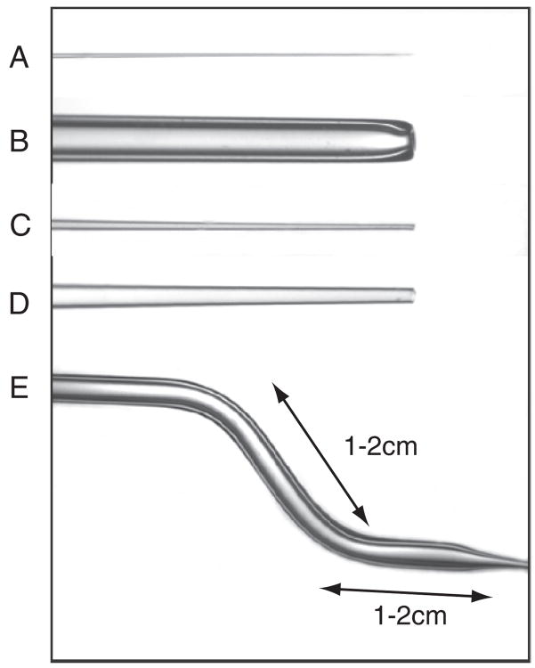
Tools used for micromanipulation of 6.5–8.5-d mouse embryos. A The glass needle, B the holding pipet, C the injection pipet used for delivering dye or DNA solution, D the pipet used for grafting cell clumps, and E the two bends produced in the pipet (shown in B–D) to enable the tip of the pipet to reach over the wall and access the medium drops sitting on the bottom of the culture dish during micromanipulation (for setting up, see Fig. 5B).
Fig. 5.
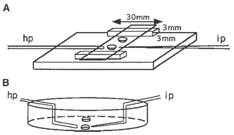
A The manipulation chamber used for manipulating 6.5-d embryos in hanging drops. The base of the manipulation chamber is made of glass of good optical quality supplied by an optometrist. The dimension of the glass strips supporting the cover slip is 3 × 3 × 30 mm. They are set between 4 and 6 mm from the edge. Two drops of solution are placed on the cover slip approximately 1 cm apart, then the coverslip is inverted over the paraffin oil-filled chamber: hp, holding pipet; ip, injection pipet. B The petri dish setup used for manipulating 7.5- and 8.5-d embryos. Two drops are placed approximately 1 cm apart in the center of the dish then covered with paraffin oil. Angled pipets are used: hp, holding pipet; ip, injection pipet.
Table 2.
The composition of Tyrodes ringer saline for electroporation of embryos
| Compound | g/500 mL |
|---|---|
| NaCl | 4.0 |
| KCl | 0.15 |
| NaH2PO4·2H2O | 0.0465 |
| KH2PO4 | 0.0125 |
| NaHCO3 | 0.5 |
| Glucose | 1.0 |
3. Methods
3.1. Culturing 6.5–8.5-d Embryos
3.1.1. Preparation of Culture Media
3.1.1.1. Preparation of DMEM
Dissolve the contents of one packet of powdered formula in 0.95 L super quality water (less 5% of the final volume required).
Stir gently at room temperature until the contents dissolve.
Add 2.2 g of NaHCO3.
Bring the volume up to 1 L.
Sterilize immediately with a 0.22-μm Millipore filter using positive pressure.
Test sterility of a 5-mL aliquot from each bottle by incubating at 37°C for 3–5 d.
Before DMEM is used for culture, add 400 μL each of glutamine and penicillin–streptomycin solution to 40 mL of DMEM. Fresh glutamine and penicillin–streptomycin should be added to the DMEM working solution after 2 wk. The working solution is good for 4 wk after preparation when kept at 4°C.
3.1.1.2. Collection of Rat Serum (RS)
Anesthetize the rat using 5% halothane in 1–1.5 L of O2.
Blood is collected from the anesthetized rat by drawing blood from the aorta into a nonheparinized syringe using a G20 hypodermic needle.
Dispense the freshly collected blood in 15-mL centrifuge tubes and centrifuge at 3,000 rpm for 10 min (Notes 1 and 2).
Grasp the fibrin clot with a flame-sterilized forceps, and spool it around the shaft of the forceps to squeeze out the serum trapped in the clot.
Transfer the serum to a new centrifuge tube using an autoclaved Pasteur pipet, and spin again at 3,000 rpm for 10 min.
Collect the serum from the second spin aseptically and store at −20°C.
3.1.1.3. Collection Of Human Cord Serum (HCS)
3.1.2. Static Culture in Four-Well Chamber Slides at 37°C in 5% CO2 in Air
Thaw the required volume of HCS and RS, and inactivate the sera on day of use by heating for 30 min in a water bath at 56°C, 3.2 mL of culture medium is required for one chamber slide, and this is made up of 0.8 mL HCS, 1.6 mL RS, and 0.8 mL DMEM (1:2:1 by volume). Alternatively, use 100% RS to culture 6.5–7-d embryos.
Put 0.5 mL in the first well (Note 3) and 0.9 mL in the remaining three wells. This volume is sufficient for culturing groups of 8–10 6.5-d embryos/well (Note 4) for up to 48 h (Note 5). The 7.5-d embryos can be cultured for up to 24 h by the static culture method (Note 6)
3.1.3. Roller Bottle Culture (with Continuous Gassing) for 7.5–8.5-d Embryos
The 7.5- or 8.5-d embryos are cultured for 24 h in a medium of DMEM:RS (1:3 by volume). Use 1 mL and 3 mL of culture medium per 7.5-d or 8.5-d embryo, respectively. Four to five 7.5-d and two to three 8.5-d embryos can be cultured in one 30-mL bottle. Bottles are maintained in a BTC embryo culture chamber at 37°C in 5% O2, 5% CO2, and 90% N2, and are rotated on a roller/rotator at 30 rpm.
Embryos are transferred to a fresh medium of DMEM:RS (1:3 by volume) if culturing beyond the first 24 h. The gas phase remains the same for 7.5-d + 24-h embryos. For 8.5-d + 24-h embryos, the gas phase is changed to 20% O2, 5% CO2, and 75% N2 (11).
3.2. Isolation of Tissue Fragments for Grafting
3.2.1. Making Glass Needles (Fig. 1A)
Attach a hypodermic syringe with a G20 needle to a bunsen burner connected to a butane gas cylinder. Adjust the gas flow by a regulator to produce a small flame.
Heat the “Microcaps” micropipets in the flame until the glass melts into a short solid segment.
Pull the fused segment of the capillary in a vertical pipet puller to produce two thinly drawn needles.
Coat the needle with Repelcote (BDH Chemicals, Poole, UK) to prevent the tissue from adhering during microdissection.
3.2.2. Isolation of Epiblast Fragment from 6.5-d Embryos
Position the embryo for easiest access to the epiblast cells required for transplantation. For example, if anterior or posterior epiblast cells are to be isolated, the embryo could be positioned with the sagittal plane in view (Note 7). However, to dissect cells from the lateral epiblast, the embryo is best oriented with the frontal view in sight.
Pin the embryo to the petri dish using a sharp metal needle. Hold it at the site immediately adjacent to the tissue fragment required for grafting. Another tungsten needle is used to slice through the epiblast in a scissorlike action against the first needle. Another cut is then made at an angle to the first, so that the tissue fragment is released from the epiblast. The dissection is shown in Fig. 2.
The endoderm usually remains attached to the epiblast. Make several scratch marks on the bottom of the petri dish with a metal needle. To remove the endoderm, place the tissue fragment, endoderm side down, on the grid and nudge the fragment onto the scratched surface. When the endoderm sticks to the surface, the epiblast layer can be torn away with metal or glass needles.
Cut the epiblast fragments into clumps of 5–10 cells for grafting using glass needles.
Fig. 2.
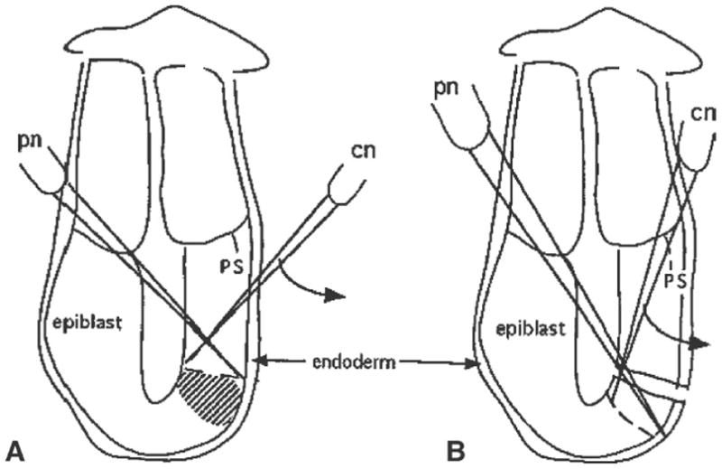
The steps taken to isolate epiblast fragments from sites adjacent to the distal cap region on the posterior side of a 6.5-d embryo. A Position of the pinning needle (pn) and the line of cut that will be made by the cutting needle (cn) just proximal to the required tissues (shaded area). B Second cut made to isolate the tissue fragment. Similar cutting actions are employed to isolate tissue fragments from other regions of the embryo. Curved arrows indicate the direction of slicing made by the cutting needle. Abbreviation: ps, primitive streak.
3.2.3. Separation of the Germ Layers of 7.0–7.5-d Embryos
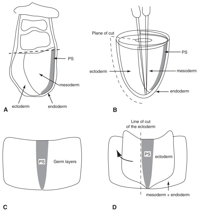
Cut the embryo at the junction between the embryonic and extraembryonic tissue (Fig. 3A).
Incubate the embryonic tissue in a trypsin–pancreatin solution (see section 2.2) for 5–10 min or until the endoderm is loosened from the mesoderm.
Transfer the embryonic fragment to three changes of PB1 + 10% FCS to stop the enzyme digestion.
Separate the germ layers as shown in Fig. 3B–D.
Cut the isolated germ layers into clumps of 5–10 cells using glass needles.
Fig. 3.
The steps of germ layer separation of 7.0–7.5-d embryos. A Tissue organization of the 7.5-d embryo. The dashed line marks the position of the first cut at the junction between the embryonic and extraembryonic parts of the egg cylinder. B The embryonic portion of the embryo that reveals the anatomical relationship of the three germ layers. A metal needle is pushed into the amniotic cavity and pins the egg cylinder in the upright position. The second metal needle is then brought inside the amniotic cavity, and the embryo is cut along the anterior side (indicated by the dashed line) by slicing the second needle through all germ layers. C The embryo opened out flat and ready for enzyme digestion. D The ectoderm layer that has been loosened by enzymatic digestion. The ectoderm can be lifted up and torn away from the mesoderm using needles. It is not possible to separate the germ layers at the site of the primitive streak. The ectoderm is therefore cut along the dashed line, where no further separation from the underlying primitive streak could be made. The mesoderm layer can be separated from the endoderm in the same manner, followed again by cutting them close to the primitive streak. The remaining tissue is the primitive streak (PS).
3.2.4. Isolation of Mesoderm and Premigratory Neural Crest Cells of 8.5-d Embryos
Remove the yolk sac and the amnion using fine watchmaker forceps.
Bisect the embryo using tungsten needles along its midline.
Make transverse cuts (using metal needles) along the neuromeric junctions to isolate wedge-shaped fragments containing the tissue to be transplanted by (7, 8). For example, to isolate somitomere IV and the middle hindbrain neural crest cells, transverse cuts should be made at the preotic sulcus and the otic sulcus.
Incubate the embryonic fragments in the trypsin-pancreatin solution for 20 min at 37°C. When the mesoderm and ectoderm layers are loosened, separate the tissue layers using glass needles.
Dissect the isolated mesoderm or neuroectoderm using glass needles into small clumps of five to ten cells (see Note 8).
3.3. Labeling and Grafting of Cells in 6.5–7.5-d Embryos
3.3.1. Making Pipets
3.3.1.1. Making Holding Pipets
The holding pipets are made using Leitz thick-wall glass capillaries. The internal diameter of holding pipets should be 10–50 μm, depending on the size of the embryo used for the experiment.
Attach a hypodermic syringe with a G20 needle to a bunsen burner connected to butane gas cylinder. Adjust the gas flow by a regulator to produce a small flame.
Hold the middle portion of the capillary over the flame until the glass starts to melt.
Take the capillary away from the flame, and pull from both ends to produce a thin segment of capillary.
Break the drawn capillary in the middle with a diamond pencil.
Polish the holding pipets on a microforge. A small glass bead is melted onto the platinum wire of the microforge. Heat the glass bead by increasing the electric current until the platinum wire glows red hot. Bring the tip of the pipet as close as possible to the glowing glass until it melts under the heat of the glass bead. Retract the pipet from the glass bead when a polished tip is produced (Fig. 1B; see Note 9).
3.3.1.2. Making Injection and Grafting Pipets
Injection pipets with an inner diameter of about 1–2 μm are made from thin-walled glass capillaries. The internal diameter of grafting pipets is larger and varies according to the size of the clumps of cells to be grafted.
Pull glass capillaries on a vertical or horizontal pipet puller to produce pipets with a fine tip, a long shaft, and a short shoulder (Note 10).
Break off the tip of the injection pipet by touching it against the cold glass bead on the filament of a microforge. This will produce a pipet for dye labeling (Fig. 1C).
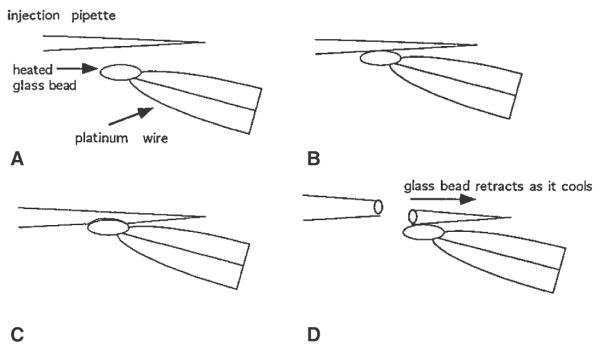
To make grafting pipets (Fig. 1D), pull the glass capillary as in step 1. Determine a position on the shaft of the pipet by measuring with a ocular micrometer on the eyepiece of the microscope of the microforge, where the glass capillary has an inner diameter appropriate for the size of the cell clumps. Break the shaft of the pipet (Fig. 4) by (1) bringing the pipet to the heated glass bead on the microforge filament so that the site of intended break just touches the bead; or (2) as the capillary begins to fuse with the glass bead, turn off the power supply to the filament to cool down the filament instantly. The retraction of the filament as it cools down will snap the pipet precisely at where the capillary fuses to the bead.
Beveled pipets are made from the grafting pipet made in step 3 (Fig. 3D; Notes 10 and 11). Touch one side of the pipet with the heated glass bead. When the pipet tip fuses with the bead, slowly withdraw the pipet to pull a sharp bevel of about 5 μm in length.
Fig. 4.
Making grafting pipets. A glass bead is attached to the tip of the heating filament of the microforge. The bead can be heated and cooled instantly by switching on and off the current of the heating filament. The current is adjusted to yield the optimal heating appropriate to the thickness and the thermal property of the glass capillary. A, B The heated glass bead contacts the shaft of the pipet at the position that gives the desired internal diameter. C Melting the capillary wall into the glass bead. D The resultant break in the pipet after the bead cools down and retracts when the current is switched off. This produces a pipet of the desired internal diameter and an even tip.
3.3.1.3. Angled Pipets
Make holding, grafting, and injection pipets as described in sections 3.3.1.1 and 3.3.1.2.
Heat the pipet, over a flame, 1–2 cm from the tip of the injection pipet. It is heated until it is bent to an angle of approx 100°.
Turn the pipet 180°, and heat the pipet at a position 1–2 cm further proximal of the first bend. Again the pipet is bent at an angle of approx 100°. (Fig. 1E).
3.3.1.4. Making Transfer Pipets for 6.5–7.5-D Embryos
Heat the shaft of the Pasteur pipet over a flame.
When the glass begins to melt, take the pipet away from the flame and hand-pull the pipet to produce a segment of thin capillary.
Break the capillary by bending the pipet. Check the size of the pipet tip under the dissecting microscope (0.5 mm for 6.5-d embryos and 1–1.5 mm for 7.5-d embryos).
Connect the pipet with a flexible plastic tube to a mouthpiece. The movement of fluid and embryo in the pipet is controlled by suction or blowing into the mouthpiece.
3.3.2. Labeling the Germ Layers of 6.5–7.5-d Embryos with Carbocyanine Dye
In labeling the germ layers, various techniques are employed, depending on the layer of interest. Carbocyanine dye is microinjected when labeling the epiblast or ectoderm and the mesoderm. This is done by pushing the dye-filled injection pipet into the appropriate layer of the embryo and expelling the dye. For labeling the endoderm, carbocyanine dye is painted onto the surface of the embryo.
Embryos are manipulated in a hanging drop under a Laborlux S microscope. Set up the micromanipulation chamber as in Fig. 5A.
Place a 5-μL drop of media (10% FCS in PB1) for holding the embryos during manipulation on a coverslip using a transfer pipet. A second 5-μL drop of dye is placed approximately 1 cm from the first drop (Note 12; Fig. 5A).
Invert the coverslip, and place it across the two glass strips of the chamber.
Fill the chamber with light paraffin oil.
To transfer embryos into the manipulation chamber, place the chamber under a dissecting microscope with the drops in focus. Pick up the embryos using a mouth-controlled transfer pipet. Pass the pipet through the oil to reach the drop and gently expel the embryo with a small volume of medium.
Set up the manipulation apparatus as shown in Fig. 6. Attach the holding pipet to the instrument holder on the left manipulator. Attach injection pipet to the instrument holder on the right manipulator. The holding pipet is controlled by the micrometer syringe on the right, whereas the injection pipet is controlled by the de Fonbrune syringe on the left. With this configuration, the positioning of the manipulator and the control of the syringe can be performed simultaneously.
Back fill the holding and injection pipets with heavy paraffin oil by adjusting the syringes.
Position the manipulation chamber, and adjust the microscope to focus on the medium drop containing the embryos.
Bring the holding pipet into the field of view by pushing it through the oil into the drop. Draw a small amount of medium into the holding pipet to create an oil medium meniscus.
Bring the injection pipet into view. Make sure that no medium is taken into the pipet, because contact with an aqueous solution causes precipitation of the carbo-cyanine dye (Note 12).
Retract the holding and injection pipets from the medium drop (Note 13). Bring the dye drop into the field of view by moving the stage of the microscope (Note 14).
Dip the tip of the injection pipet into the dye drop, and draw a small amount of dye into the pipet using the de Fonbrune syringe. Always keep the dye–oil meniscus in view, since this offers the only means for monitoring the flow of dye during labeling. Take the injection pipet out of the dye when the dye–oil meniscus stops moving.
Bring the medium drop containing the embryos back into the field of view.
Position the embryo by pushing it with the pipets and rotating it by lifting the pipet from beneath the embryo.
After the embryo is oriented correctly, bring the embryo into focus using the focusing control of the microscope, then bring the injection and holding pipets into focus using the control knob on the manipulators (Fig. 6). Touch the injection and holding pipets lightly against the embryo to confirm that they are in the same plane.
Bring the holding pipet into contact with the endoderm of the embryo next to the epiblast to be labeled. Apply a suction force using the micrometer syringe to draw the embryo against the holding pipet. Increase the suction so that a small area of the endoderm layer is partly drawn into the holding pipet (Fig. 7).
Push the injection pipet through the extraembryonic tissue into the amniotic cavity (Note 15). Then push the pipet tip into the epiblast layer (Fig. 7). When labeling the endoderm, the dye is partially expelled from the tip of the micropipette and the bolus of dye is then brought into contact with the apical surface of the endodermal layer and the cells are “painted” by moving the dye bolus against the cell surface.
Apply pressure via the de Fonbrune syringe to expel a small volume of dye into the epiblast. It is important to monitor the movement of the dye front to avoid injecting any oil into the embryo (Note 16).
Once the dye front has stopped advancing, retract the injection pipet.
Release the embryo from the holding pipet by applying a positive pressure via the micrometer syringe. Return the embryo to the culture medium (section 3.1).
Fig. 6.
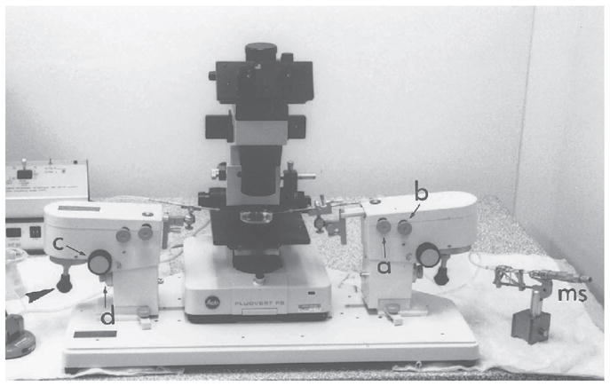
The micromanipulation assembly. The manipulators are clamped to the base plate. Each manipulator can hold up to two instrument holders. Movement of the instruments is controlled by screw-knobs (a and b) that allow positioning of the manipulator in the X–Y horizontal plane. There is a third control (c) by which the angle of inclination of the manipulator can be adjusted. Coarse and fine adjustment of the position of the manipulator in the Z-vertical plane is controlled by the fourth knob (d). Fine X–Y movement of the instrument under the microscope is controlled by joysticks (arrowhead). The holding instrument is on the left-hand side of the assembly and the suction and expulsion of fluid are controlled by the micrometer syringe (ms) on the right-hand side. Conversely, the manipulating (labeling or grafting) instruments are on the right-hand side, controlled by the de Fonbrune syringe (fs) on the left-hand side. This setup enables the positioning of the instruments and the control of syringe to be accomplished simultaneously.
Fig. 7.
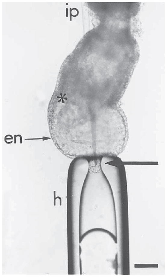
Labeling of the epiblast by microinjecting DiI into the distal cap of the embryo. To inject in the midline, the embryo is held at the distal tip of the egg cylinder by gentle suction with the holding pipet (h). The injection pipet (ip) is passed through the extraembryonic tissues of the egg cylinder. The injection pipet is brought to the site of labeling from within the pro-amniotic cavity to avoid inadvertent labeling of other embryonic germ layers. The arrow points to the tip of the labeling pipet in the epiblast layer: en, primitive endoderm; *primitive streak. Bar = 20 μm.
3.3.3. Electroporating Gene Expression Construct into Germ Layer of 7–7.5-d Embryos
3.3.3.1. Setup of Electroporation Apparatus
Flatten the end of a 3-cm platinum wire into a plate and solder the other end of the wire onto a banana socket.
Solder a tungsten wire onto a banana plug. Sharpen the end of the wire by dipping it in a 3-M NaOH bath connected to a 6-V lantern battery. Attach the banana socket fused to the platinum plate onto a 150-mm petri dish with plasticine. Make a hole on side of lid of a 60-mm petri dish, insert the platinum plate through hole, and attach a thin piece of plastic tubing covering the wire, leaving the plate exposed (Note 17).
Connect the platinum plate and tungsten wire to an Electro Square Porator, so that the platinum plate is the positive pole and the wire is the negative pole (this arrangement may have to be reversed with different electroporation experiments).
Set up the micromanipulation apparatus and attach the holding pipet as described in section 3.3.2, steps 6–9, except that an injection pipet and light paraffin oil is not used.
Place a drop of Tyrode’s Ringer saline over the platinum plate until it is completely immersed. Place a separate drop of PB1 on the petri dish.
Attach the banana plug holding the tungsten wire to a positioner. Bring holding pipet, platinum plate, and tungsten wire into the field of view on the micromanipulator apparatus. Position the tungsten wire until it is at same focal plane under the microscope as the platinum plate, but leave a small gap between them.
3.3.3.2. Electroporating Expression DNA Construct Into a Cell of the Endoderm of 7–7.5-D Embryos
Using a mouth-controlled transfer pipet place about seven embryos in PB1 in smallest drop possible (5–10 μL) on the petri dish.
Add (5 μL) concentrated plasmid DNA solution (aqueous, concentration ranges from 2–5 μg/μL) onto the pool of embryos and pipet the solution up and down to mix the two solutions together so that the final DNA concentration is 1–2 μg/μL Incubate the embryos for at least 5 min.
Using a mouth-controlled pipet carefully pick up one embryo from the drop with minimal amount of DNA solution and transfer the embryo to the electroporation drop of Tyrode’s Ringer saline (Note 18).
Bring the electrodes into the field of view around the embryo
Position the embryo between the two electrodes using the holding pipet as in section 3.3.2, steps 14–16, except that the embryo is held on the side opposite the site of electroporation (Note 19).
Position the embryo between the platinum plate and tungsten wire so that the embryo touches both the plate and the wire (the latter with the endoderm at the site of electroporation).
Move the wire and the plate slightly apart and reposition the embryo so that the embryo stays in the gap between the wire and the plate but not touching either electrode (Fig. 8A; Note 20). Set the Electro Square Porator to deliver five pulses at 15 V at 50 ms apart. Switch on the electroporator.
Release the embryo from the holding pipet by applying a positive pressure via the micrometer syringe. Pick up the embryo using a Pasteur pipet and place it in the drop of PB1 (Note 21).
Repeat steps 1–7 for each embryo until all are electroporated (Note 22).
Culture the embryos initially for 3 h in static culture medium as in section 3.1.2 in 100% RS (for 7.0-d embryos) and DMEM:RS (1:3 by vol; for 7.5-d embryos) (Note 23).
After 3 h, the embryos are photographed as in section 3.5.3 to visualize the location of the electroporated cells if fluorescent constructs are employed for labeling (Fig. 8B; Note 24)
Transfer embryos to the roller culture incubator as in section 3.1.3 and culture for the required duration of the specific experiment.
Fig. 8.
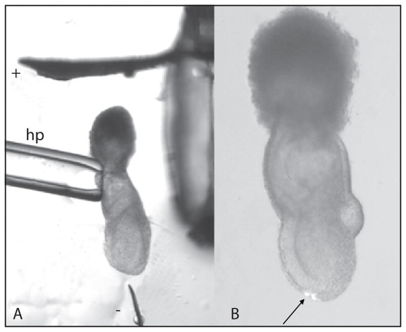
Labeling the endoderm of 7.0-d embryo by electroporation. A The embryo is first bathed in plasmid DNA solution before transfer to the electroporation drop on the culture dish. To electroporate the distal tip, the embryo is held at the extraembryonic ectoderm by suction using the holding pipet (hp) and positioned between the platinum plate (cathode) and tungsten needle (anode). The electrodes are connected to an Electro Square Porator and the electroporation is focused at the tissue closest to the needle tip. B Fluorescent cells in the distal region of the embryo following electroporation with a β-actin-eGFP construct and cultured for 3 h.
3.3.3.3. Electroporating Gene Construct Into a Cell of the Epiblast or Ectoderm in 7–7.5-D Embryos
Assemble the electroporation apparatus and the micromanipulation apparatus as in section 3.3.3.1, steps 1–6, except that the plate is set as the negative pole and the wire is set as the positive pole. Targeting the epiblast or ectoderm requires that the polarity arrangement is reversed, so that the DNA enters via the apical surface of the epiblast or ectoderm as it is driven toward the needle electrode.
Inject plasmid DNA into the amniotic cavity as in section 3.3.2, steps 1–20, except that the plasmid DNA solution is injected instead of carbocyanine dye. It is easier if another manipulator is used for injecting, so the injecting pipet does not interfere with the electroporation apparatus if they are set up on the same micromanipulator.
Pick up the embryo using mouth-controlled transfer pipet and place into the drop containing Tyrodes ringer saline.
Position, electroporate, and culture the embryo as in section 3.3.3.2, steps 4–9, and take images of fluorescent embryo (if a fluorescent gene constructs are used) at 3 h and other appropriate times as in section 3.5.3.
3.3.4. Grafting Epiblast Fragments to 6.5-d Embryos
Place two drops of PB1 (+10% FCS) medium approximately 1 cm apart on the coverslip, and set up the manipulation chamber as section 3.3.2, steps 1–4.
Set up the manipulation apparatus, and position the pipets as described in section 3.3.2, steps 5–9.
Position and hold the embryo as in section 3.3.2, steps 14–16, except that the embryos is held on the side opposite to the site of grafting (Fig. 9).
Pick up the cell clumps into the grafting pipet with a small amount of medium. Draw the cell clumps about 20 μm into the grafting pipet.
Insert the grafting pipette by a sharp jabbing action through all tissue layers into the pro-amniotic cavity at the site of transplantation. If necessary, a beveled pipet may be used.
Apply a positive pressure to the de Fonbrune syringe to expel the graft from the pipet as the pipet is slowly withdrawn from the embryo (Notes 25–27). A coordinated movement of the pipet and the expulsion of the graft is critical to the precise positioning of the graft in the epiblast.
Return the embryo to the culture medium (section 3.1).
Fig. 9.
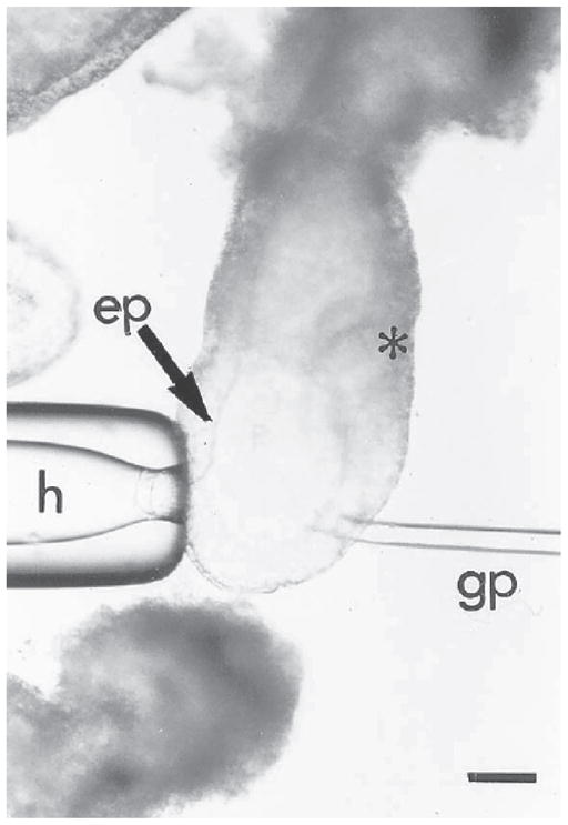
Grafting of cells to a 6.5-d embryo. The embryo is held on the anterior side opposite the intended site of grafting by the holding pipet (h). The cells are grafted into the epiblast (ep) on the posterior side of the embryo (*marks the position of the primitive streak) immediately proximal to the margin of the distal cap. Bar = 20 μm.
3.3.5. Grafting of Cells
Place a 50-μL drop of medium (the manipulation drop) slightly off-center in the lid of a petri dish. Place another drop of medium (for holding cells for grafting) next to the first drop (Fig. 5B).
Fill the petri dish with light paraffin oil to cover the drops.
Transfer embryos from the culture to the manipulation drop in the petri dish by mouth pipeting.
Angled pipets are used for holding and grafting cells into the embryos. Place the pipets in the instrument holders of the manipulator. Tilt the manipulators so that the tips of the pipets are immersed in the paraffin oil and point to the bottom of the petri dish. Figure 6 shows the setup for manipulating 7.5-d embryos.
Focus the microscope on the embryos in the manipulation drop. Lower the pipets into the drop. Manipulation is carried out according to section 3.3.2, steps 7–20; section 3.3.4, steps 3–7; and Note 28.
3.4. Transplanting and Labeling Cells in the Cranial Region of 8.5-d Embryos
3.4.1. Making Transfer Pipets
Embryos that are 8.5 d old are transferred using Pasteur pipets that are cut at the shaft to give an internal diameter of about 3–4 mm. This allows the embryos to be transferred without damage to the yolk sac.
3.4.2. Manipulation
Embryos that are 8.5 d old are manipulated in a petri dish in the same way as described in section 3.3.5, steps 1–4.
Orient the embryo using fine watchmaker forceps.
Hold the embryo by the yolk sac with the holding pipet by applying negative pressure to the micrometer syringe. The embryo is positioned so that a clear silhouette of the cranial neural fold is visible.
Insert the injection and grafting pipet through the yolk sac then the amnion into the amniotic cavity.
Push the pipet gently into the cranial neural fold or further into the cranial mesoderm.
Expel the cell clumps or dye by applying a positive pressure to the de Fonbrune syringe. Expulsion of the cell clumps is accompanied by the simultaneous withdrawal of the pipet.
For dye delivery, the pipet remains in position until the dye front has stopped moving toward the tip.
Return the embryo to culture (section 3.1.3).
3.5. Analysis of Labeled Embryos
Dye-labeled embryos are analyzed by fluorescence microscopy. Fluorescent detection indicates the location of the labeled cells within the embryos. More detailed analysis can be carried out by confocal microscopy.
3.5.1. Preparation of Embryos for Confocal Microscopy
For confocal microscopy, embryos are analyzed in whole mount. Embryos that are 8.5 d old and older need to have the extraembryonic tissues dissected away. Embryos that are 6.5 and 7.5 d old are analyzed intact.
Embryos are mounted flat under a coverslip (cover glass number 1½). To allow sufficient space for the embryos between the slide and the coverslip, small bluetac feet are placed at the four corners of the coverslip (Note 29).
The slide is filled with PBS and sealed with nail polish.
3.5.2. Confocal Analysis
A confocal microscope allows one to obtain an image of the fluorescent label and a transmission image of the embryo. The two images can be overlaid to identify where along the anterior posterior axis of the embryo the labeled cells are located. The depth of the sections of the fluorescent label gives some indication of which tissue layer contains the labeled cells.
3.5.3. Imaging Live Embryos Using Fluorescence Microscopy
As indicated previously, expression of fluorescent protein can be visualized by fluorescence microscopy.
Live or fixed embryos are examined using a fluorescence stereomicroscope system (Leica MZ FLIII) using excitation filter GFP-1 filter set, 425 nm.
Photographs are taken using a SPOT Advanced digital camera (version 3.5.9.1).
During photography, live embryos are kept in warmed PB1(~37°C) while fixed embryos (in 4% paraformaldehyde) are in PBS.
For each specimen, both bright field and fluorescent images are captured.
From the bright field image, a red-color scan is extracted by selecting for the red channel capture. This red-channel image is merged with the true-color fluorescent image by Adobe Photoshop 7.0 for showing the position of the fluorescent cells in the embryonic structures (Note 30).
3.5.4. Analysis of Grafted Embryos
The distribution of graft-derived cells may be analyzed in whole mount or on serial sections of the embryo if the cells are marked by lacZ transgene. For protocols used to visualize the transgenic cells, see Chapter 10.
Footnotes
It is important that the rat and cord blood are spun as soon as possible after collection, preferably before clotting commences. The serum obtained by squeezing the fibrin clot is known as the immediately centrifuged serum.
Serum used as medium supplement should have a low lipid content (clear instead of cloudy). Hemolyzed serum does not support normal culture of mouse embryos.
The medium in the first well of the NUNC slide is used to wash the embryo once before transferring to the culture wells.
Growth rates decline if the embryos are overcrowded and, likewise, if they are cultured alone.
Best development for 48 h is achieved with embryos explanted shortly after the appearance of the primitive streak.
The successful culturing of 5.5-d embryos was recently described using similar culture medium. Using a micromanipulator, hold the 5.5-d embryo with a holding pipet and remove the Reichardt membrane a glass needle. Culture in a medium of DMEM:RS (1:1 and 1:3 by volume) for up to 48 h (11).
The appearance of the primitive streak provides an unequivocal indication of the anterior–posterior axis and helps with the orientation during dissection. Early gastrulation embryos are therefore used in experiments that demand knowledge of the source of cells in the anterior–posterior and medial–lateral axis. However, if only a distinction between proximal and distal epiblast is required, both pre- (without the primitive streak) and early gastrulation embryos can be used.
The choice of developmental stage is important to avoid contamination of the cranial mesoderm by migrating neural crest cells. Previous studies have established that the first population of neural crest cells to leave the neural plate are those of the mesencephalon at the 5–6 somite stage (12–16). Therefore, in experiments involving the cranial mesoderm, only embryos having ≤5 somites are used, so that the mesodermal explants are free of any migrating neural crest cells. To obtain an enriched neural crest cell population for cell fate analysis, premigratory neural crest cells are isolated from the lateral region of the neural plate of these embryos for transplantation experiments.
It is important that the holding pipette has a smooth surface so that the embryo is not damaged when it is held against the tip by suction.
If the internal diameter of the grafting pipet is large relative to the size of the embryo, it may be difficult to puncture the tissue layers with the pipet during grafting. Beveled pipets can be used in this situation. The sharp point of the beveled pipet slices the tissue layers to create a passage for the grafting pipet.
Do not overheat the glass bead, since this may cause distortion and constriction of the pipet tip. It is useful to mark the side of the pipet with the bevel for later orientation.
The drops should be placed far enough apart to avoid mixing of contents as the pipets are moved around in the chamber.
When moving between the dye drop and the media drop, the holding pipet should be retracted, so that its tip does not become contaminated with the dye.
When drawing up the dye solution, it is best to keep the edge of the dye drop in sight, so that only the tip of the pipet is dipped into the dye drop. Pushing the pipet too far into the drop results in an excessive amount of dye adhering to the outer surface of the pipet.
Labeling of the embryonic tissue is best accomplished through the extraembryonic route, because it reduces the chance of accidentally labeling other germ layers. Even if dye is leaking from the pipet or coming off the surface of the pipet during the passage of the pipet, only the extraembryonic tissues are inadvertently labeled.
The pipets may clog with precipitate of the dye after repeated uses. The clogged pipet can be recovered by breaking its tip by brushing against the holding pipet while in the chamber or by wiping it gently with a lint-free tissue when it has been taken out of the chamber.
The lids of petri dishes are used because the rim has a lower clearance, which gives better accessibility of the angled pipets to the embryos and tissues in the dish.
Fill the mouth-controlled pipet with Tyrode’s ringer saline first, so that the embryo and only a small amount of DNA solution enter the pipet by capillary action. Also release the embryo into the electroporation drop with minimal DNA solution.
Holding the embryo at the ectoplacental cone or the extrambryonic ectoderm is preferred to holding the embryo proper, so the embryo’s outer germ layers are not disturbed. The holding pipet need not be as close on the opposite side of the embryo as for injecting dye or cells. However, during pulses, the current flowing can cause the embryo to swing, which could be overcome by holding the embryo closer to the site of electroporation.
Air bubbles emit from the tungsten wire, indicating the current has been generated. It is essential that the embryo is correctly spaced between the plate and wire such that large bubbles emitting from the plate and wire do not touch and burn the embryo and also that the targeted embryo site is close to the wire to allow focused point of electroporation.
A separate pipet is used, so the mouth controlled pipet is reserved for transferring embryos from DNA solution, thus reducing dilution of DNA solution.
Electroporation has to be done fairly swiftly to minimize the time spent by the embryo in DNA solution or Tyrode’s solution.
Initial culture in static culture may improve the viability of the embryo, which may have sustained damage by electroporation.
Our data show that it requires 2–3 h for sufficient protein to be synthesized to enable detection of fluorescence.
If the cell clumps become sticky, they will follow the grafting pipet out of the embryo. Leave the pipet with the graft partly out of the tip at the transplantation site for 10–30 s to allow the graft to adhere to the surrounding tissue. Following that, a snappy retraction of the grafting pipet or tapping gently on the base plate of the manipulator may dislodge the graft from the pipet tip. Siliconizing the injection glassware also stops the cell clumps from adhering to the injection pipets.
Occasionally, the host embryos collapse because of fluid leakage through the wound made to accommodate the graft. Inflating the embryonic cavity by injecting a small amount of medium to replenish the loss of fluid during transplantation may improve the development of the embryo.
A small graft is readily incorporated into the host embryo. Larger grafts may be squeezed out of the embryo as the wound closes. Pushing the tip of the grafting pipet against the graft that has been lodged in the germ layer for approximately 10–30 s helps the retention of the graft.
The principle for manipulating 7.5-d embryos is the same as for 6.5-d embryos. However, manipulations are carried out in a petri dish and therefore require the use of the fluovert FS inverted microscope.
Despite the blue-tac feet, the embryos are squashed to some extent. With 6.5- and 7.5-d embryos, it can be difficult to orient the embryos once they have been squashed. For ease of analysis, mount the embryos in the sagittal plane, and mark the direction of the anterior–posterior axis on the slide.
A red bright field image allows for better visualization of the fluorescent cells by providing a stronger contrast between the cells and the embryos
References
- 1.Lawson KA, Meneses JJ, Pedersen RA. Clonal analysis of epiblast fate during germ layer formation in the mouse embryo. Development. 1991;113:891–911. doi: 10.1242/dev.113.3.891. [DOI] [PubMed] [Google Scholar]
- 2.Quinlan GA, Williams EA, Tan S-S, Tam PPL. Neuroectodermal fate of epiblast cells in the distal cap region of the mouse egg cylinder: implication for body plan organisation during early embryogenesis. Development. 1995;121:87–984. doi: 10.1242/dev.121.1.87. [DOI] [PubMed] [Google Scholar]
- 3.Parameswaran M, Tam PPL. Regionalisation of cell fate and morphogenetic movement of the mesoderm during mouse gastrulation. Develop Genet. 1995;17:16–28. doi: 10.1002/dvg.1020170104. [DOI] [PubMed] [Google Scholar]
- 4.Tam PPL, Beddington RSP. The formation of mesodermal tissues in the mouse embryo during gastrulation and early organogenesis. Development. 1987;99:109–126. doi: 10.1242/dev.99.1.109. [DOI] [PubMed] [Google Scholar]
- 5.Tam PPL, Beddington RSP. Establishing and organisation of germ layers in the gastrulating mouse embryo. Postimplantation development in the mouse, Ciba Foundation Symp; Chichester, UK: Wiley; 1992. pp. 27–49. [DOI] [PubMed] [Google Scholar]
- 6.Tam PPL. Regionalisation of mouse embryonic ectoderm: allocation of prospective ectodermal tissue during gastrulation. Development. 1989;107:55–67. doi: 10.1242/dev.107.1.55. [DOI] [PubMed] [Google Scholar]
- 7.Trainor PA, Tan S-S, Tam PPL. Cranial paraxial mesoderm: regionalisation of cell fate and impact upon craniofacial development in mouse embryos. Development. 1994;120:2397–2408. doi: 10.1242/dev.120.9.2397. [DOI] [PubMed] [Google Scholar]
- 8.Trainor PA, Tam PPL. Cranial paraxial mesoderm and neural crest cells of the mouse embryo: co-distribution in the craniofacial mesenchyme but distinct segregation in branchial arches. Development. 1995;121:2569–2582. doi: 10.1242/dev.121.8.2569. [DOI] [PubMed] [Google Scholar]
- 9.Davidson BP, Tsang TE, Khoo P-L, Gad JM, Tam PPL. Introduction of cell markers into germ layer tissues of the mouse gastrula by whole embryo electroporation. Genesis. 2003;35:57–62. doi: 10.1002/gene.10166. [DOI] [PubMed] [Google Scholar]
- 10.Beddington RSP. Induction of a second neural axis. Development. 1994;120:613–620. doi: 10.1242/dev.120.3.613. [DOI] [PubMed] [Google Scholar]
- 11.Miura S, Mishina Y. Whole-embryo culture of E5.5 mouse embryos: development to the gastrulation stage. Genesis. 2003;37:38–43. doi: 10.1002/gene.10229. [DOI] [PubMed] [Google Scholar]
- 12.Sturm K, Tam PPL. Isolation and culture of whole postimplantation embryos and their germ layer derivatives. In: Wassarman P, DePamphilis M, editors. Methods in enzymology:. guide to techniques in mouse development. Academic Press; New York: 1992. pp. 164–190. [Google Scholar]
- 13.Jacobson AG, Tam PPL. Cephalic neurulation in the mouse embryo analysed by SEM and morphometry. Anat Rec. 1982;203:375–395. doi: 10.1002/ar.1092030308. [DOI] [PubMed] [Google Scholar]
- 14.Chan WY, Tam PPL. A morphological and experimental study of the mesen-cephalic neural crest cells in the mouse embryo using wheat germ agglutinin-gold conjugates as the cell marker. Development. 1988;102:427–442. doi: 10.1242/dev.102.2.427. [DOI] [PubMed] [Google Scholar]
- 15.Serbedzija GN, Bronner-Fraser M, Fraser SE. A vital dye analysis of timing and pathways of avian neural crest cell migration. Development. 1989;106:809–816. doi: 10.1242/dev.106.4.809. [DOI] [PubMed] [Google Scholar]
- 16.Kinder SJ, Tan S-S, Tam PPL. Cell grafting and fate mapping of the early-somite-stage mouse embryo. Methods in molecular biology. 2000;1:425–437. doi: 10.1385/1-59259-685-1:425. [DOI] [PubMed] [Google Scholar]; Developmental Biology Protocols. 135 [Google Scholar]


