Abstract
The effect of focus splitting after propagation of focused ultrasound through a rib cage is investigated theoretically. It is shown that the mechanism of this effect is caused by the interference of waves from two or more spatially separated sources, such as intercostal spaces. Analytical estimates of the parameters of splitting are obtained, i.e., the number of foci, their amplitudes, diameter, and the distance between them, depending on the transducer parameters, as well as the dimensions of the rib cage and position of ribs relative to the radiator. Various configurations of the relative positioning of ribs and radiator are considered; it is shown which of them are the most effective for real surgical operations.
INTRODUCTION
In recent decades, the use of focused ultrasound in medicine for noninvasive destruction of deeply located tissues is a technology increasingly expanding in clinical practice. High-intensity focused ultrasound (HIFU) has found broad application in ultrasonic surgery [1--3]. For example, in China since the end of 1997 to the present, more than 10 000 extracorporeal (i.e., performed with a focused radiator located outside of the body) operations have been carried out in connection with treatment of tumors of liver, breast, bones, kidney, pancreas, and uterus. Outside China, more than 1000 similar operations have been performed as well. Long-term studies of side effects have demonstrated a rather low level of postoperative complications.
A substantial limitation to wider clinical spread of HIFU is the presence of strongly reflecting or strongly absorbing acoustic obstacles in tissues of the human body. These obstacles are primarily bones, in particular, chest bones, that complicate ultrasound surgical operations on the liver or heart. As it is known, the acoustical properties of bones differ strongly from the properties of soft tissues; bones absorb ultrasound much more readily, and strong reflection of ultrasound energy occurs at the bone-tissue interface. These effects lead to overheating of bones and overlying tissues, including skin [4]. Another complication, for the same reasons, is that the intensity in the focus significantly decreases and may be insufficient for destruction of tissues behind the rib cage.
In a number of studies dealing with the use of focused ultrasound in the presence of ribs, authors showed the effect of splitting of the main focus when, after ultrasound passed through the rib cage, secondary intensity maxima were observed along with the main focus. In addition, appreciable variation was observed in the structure of intensity distributions in the focal plane depending on whether the beam axis passed through a rib or through the intercostal space. For example, in [5], the source of ultrasound was a focusing radiator with a relatively small aperture, and the model simulating ribs was either one or two rectangular bars. Both calculations and experiments have shown that, in the case when the radiator axis crossed a rib, a complex interference pattern consisting of five intensity maxima was observed in the focal plane, and the value of the intensity in the main maximum significantly decreased. In the case when the radiator axis passed through the intercostal space, the effect of splitting was not observed and the peak value of intensity in the focal spot was considerably higher.
Some research groups tried to solve the problem on how to minimize heating of ribs and to increase the intensity in the focus in liver tissues in the presence of a rib cage on the HIFU propagation path. For example, in [6], numerical modeling of the ultrasound field radiated by the phased array was performed behind the rib cage. To minimize the effect of ultrasound on ribs, the elements in this virtual array for which the vectors normal to the surface of the element crossed a rib, were switched off. Modeling has shown that, along with the main focus, two secondary maxima appeared. In [7, 8] it was suggested to use the time reversal method to overcome distortions introduced in by a rib cage located on the propagation path of the focused ultrasound. It has been shown that the combined use of the time reversal method and multi element phased arrays makes it possible to achieve a substantial reduction in heating of thorax bones. However, focus splitting was still observed behind the ribs.
In relatively few publications dealing with focused ultrasound in the presence of ribs [4--8], we did not find neither discussion of the effect of focus splitting, nor references to the nature of occurrence of secondary maxima. Possible influence of this effect on safety and efficiency of ultrasound treatment were not considered either. Clearly, the occurrence of secondary intensity maxima leads to tissue overheating in undesired areas, and the intensity in the main maximum decreases in comparison to the case when there are no ribs on the ultrasound propagation path.
These questions became the subject of detailed studies presented in our recent publications [9, 10]. To prevent overheating of bones and overlying tissues, we used an approach based on switching off a part of the array elements located in front of the ribs [6]. As a source, a phased array with randomly distributed elements on the array surface (so-called random array) was used [11--16]. The effect of focus splitting after HIFU passed through bones was predicted in theory and observed in experiments [10]. The use of a random array has made it possible to steer electronically the focus and create combinations of several foci without grating lobes caused by the regular distribution of the array elements. This has made it possible to confirm in experiment the effect of splitting for a shifted focus and for a combination of several foci. The analytical model proposed in [10] has made it possible to obtain simple estimates of the parameters of splitting; and good agreement between theory and experiment has been shown.
The aim of this study was to generalize the results obtained in [10] to various practical situations that can arise in using focused ultrasound systems in surgery and to offer more detailed theoretical analysis of focus splitting for different parameters of the radiator, rib cage dimensions, and position of ribs relative to the radiator. To describe focusing of ultrasound through ribs, three models of different degree of complexity are proposed. In one of them, parabolic approximation of diffraction theory is used in calculating the acoustic field and for setting boundary conditions in the plane of ribs. Such an approach makes it possible to obtain a simple analytical solution for the field in the focal plane and to estimate the parameters of splitting s, i.e., the number of foci, their amplitude, diameter, and the distance between them. Numerical modeling of the field using the Rayleigh integral was also carried out for two types of radiators: a focused piston radiator with uniform distribution of oscillatory velocity over its surface, and the phased array described in [10, 15, 16]. In the conclusion of the paper, experimental data are presented showing the effect of focus splitting in the ablation of tissues in vitro.
THEORETICAL MODELS
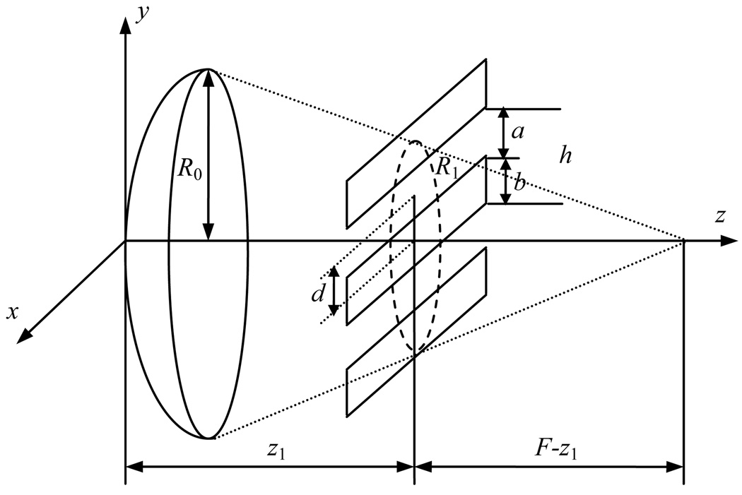
Figure 1 shows the diagram of focused ultrasound propagation through ribs. The model simulating a rib cage represents infinitely thin, absolutely absorbing parallel strips of width b with distance a between them; h = a + b is the period of the spatial structure of ribs. Notations in the figure: z1 is the distance between the center of the radiator and the plane of ribs, F is the focal length, d is the position of the middle of the intercostal space relative to the radiator axis, and R0 is the radiator radius. The dashed line represents an ultrasonic beam crossing the rib plane at the distance z1, and R1 is the effective beam radius. Ultrasound propagation in water is considered.
Fig. 1.
Geometry of propagation of focused ultrasound through ribs.
In the first model, the analytic approach based on parabolic approximation of diffraction theory was used [17, 18]. The complex amplitude of the wave oscillatory velocity was set in the intercostal spaces between the ribs within a beam aperture of radius R1:
| (1) |
and was assumed equal to zero on the ribs and outside the beam aperture. Here, k = 2πf/c0 is the wave number, f is the operation frequency of the array, and c0 is the sound speed in the medium. The amplitude of wave V0 is constant, and the phase change in the transverse coordinate providing focusing at distance F − z1 is given in the parabolic approximation. As it is known, in this case, the pressure amplitude in the focal plane is determined in a paraxial approximation by a spatial spectrum of the initial (at z = z1) distribution of the wave amplitude [17--19]. In this case, the initial spatial spectrum of the distribution (1) is the convolution V/V0 = 2πP1 (kx, ky)⊗P2(kx, ky) of spectra of the piston distribution of a round aperture with a radius R1,
| (2) |
and of the periodic function of intercostal spaces,
| (3) |
The distribution of the pressure amplitude in the focal plane can be written, having replaced kx = kx/(F − z1),ky = ky/(F − z1) [15], as
| (4) |
Then, for the intensity of a wave in the focal plane I(x, y, F) = p2 / 2ρ0 c0, the solution will be
| (5) |
where is the beam intensity in the rib plane.
In the second model, a piston radiator in the form of a spherical segment with the radius of curvature F and diameter of 2R0 was considered as an ultrasound source. In this case, it is not possible to obtain an analytical solution and the field was calculated numerically using the Rayleigh integral. At the first stage, the distribution of complex pressure amplitude pribs was calculated between the ribs:
| (6) |
Here, V0 is the amplitude of oscillatory velocity on the spherical surface of a radiator S, ρ0 is the density of the medium, and is the radius vector from point (x′, y′, z′) of the radiator surface S to point (x, y, z1) lying in the rib plane. Further, the given distribution was used as a boundary condition for calculating the pressure distribution in the focal plane:
| (7) |
In this case, R is the radius vector from point (x1, y1, z1) lying in the rib plane to point (x, y, F) in the focal plane, where the acoustic field was calculated. Intensity distribution I in the focal plane was calculated in the approximation of quasi-plane wave propagation I (x, y) = |pF (x, y)|2 / 2ρ0 c0 from the solution (7).
In the third model, as an ultrasound source, we used a phased array with an operation frequency of 1 MHz, consisting of 254 elements 7 mm in diameter each [16]. The elements were randomly distributed on the surface of a spherical shell with a curvature radius of 130 mm and a diameter of 170 mm. The minimum distance between the centers of elements was 7.9 mm, and the largest, was 9.4 mm. In the center of the array was a hole of 40 mm in diameter to mount an imaging transducer. Methods of calculating the acoustic fields created by such arrays given in [11--15, 20, 21] have been modified in [10] in application to the problem of HIFU propagation through rib cages. Intensity distributions created by the array were calculated here numerically similar to calculating the field of the piston transducer (6, 7).
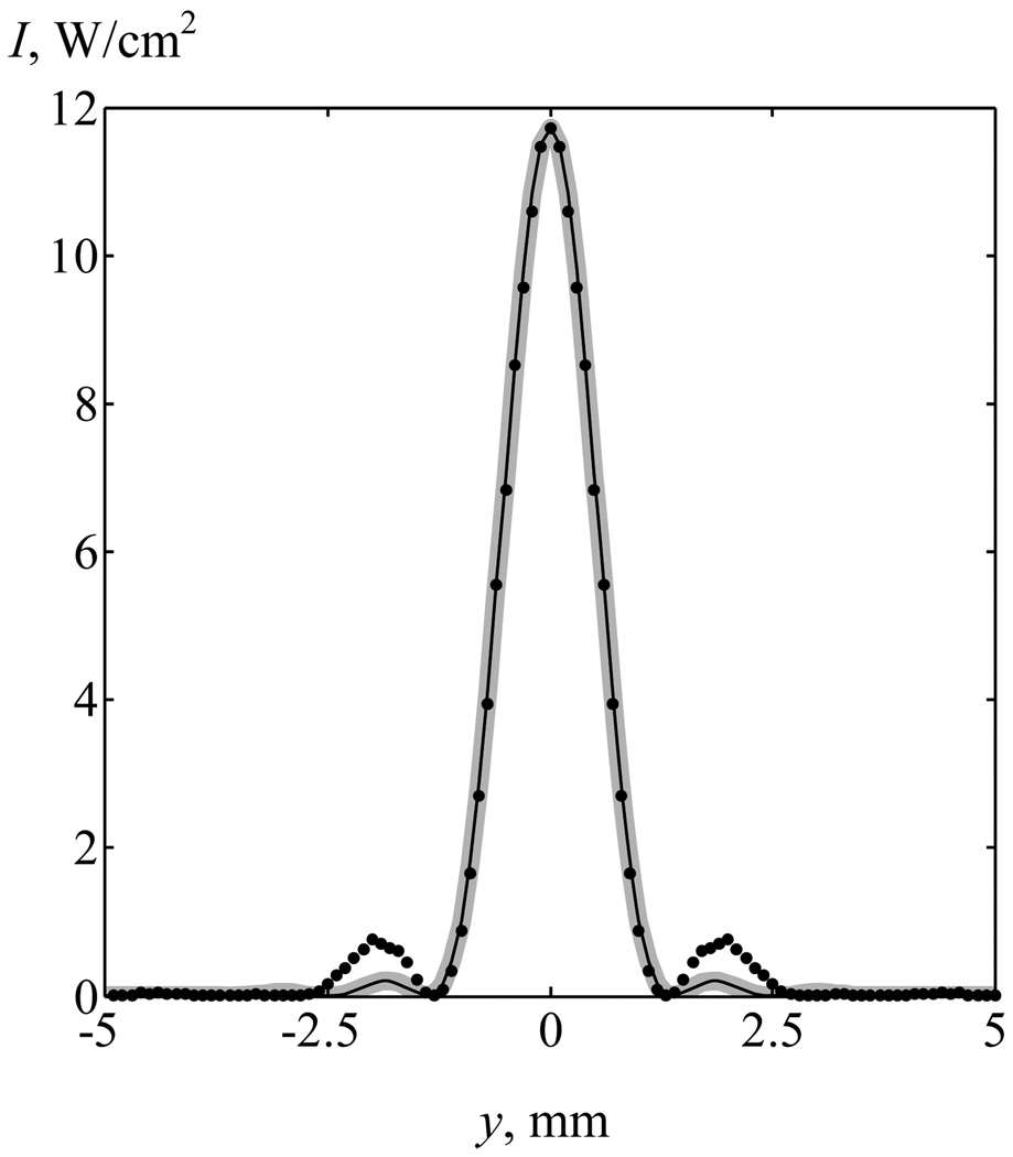
For comparison of the results, the parameters of the piston transducer and the boundary condition in analytical solution (5) were chosen such that in the absence of ribs, the intensity distributions obtained in the focal plane most closely approximated the field of the array. As a basis, the field of the array with intensity I0 = 5 W/cm2 on the surface of each element was considered. Figure 2 shows the corresponding intensity distributions for the array (points), the piston radiator with R0 = 87 mm and initial intensity I0′ = 0.9 W/cm2 (gray curve), and the analytical solution at z1=45 mm, R1 = 58 mm, and I0″ = 1.7 W/cm2 (black curve). It is seen that by selecting the dimensions and initial intensity for the piston source and the boundary condition in the analytical solution, it is possible to achieve good agreement between all three intensity distributions within the main diffraction maximum.
Fig. 2.
Intensity distributions in the focal plane in the absence of ribs for an array (a), a piston radiator (b), and analytical solution (c).
Clearly, in the analytical solution, the values of effective radius of the beam in the rib plane R1 and intensity I0″ depended on the position of the rib plane z1. In further calculations, three cases will be considered: when the rib plane is located close to the radiator (z1 = 45 mm, Fig. 2) and closer to the focus (z1 = 94 and 106 mm). For each position z1, parameters R1 and I0″ were chosen such that the analytical solution was the closest to the field of the array and the piston radiator. At z1 = 94 mm, the values of parameters were R1 = 24 mm and I0″ = 10.5 W/cm2; at z1 = 106 mm, R1 = 16 mm and I0″ = 23.5 W/cm2. Intensity distributions for the given boundary conditions coincided with the distribution for z1 = 45 mm, shown in Fig. 2.
ANALYSIS OF THE ANALYTICAL SOLUTION
Simple analytical solution (5) makes it possible to analyze the structural features of the intensity field in the focal plane depending on the ratio of the dimensions of the beam and ribs, as well as the position of the beam axis relative to the middle of the intercostal space. In terms of practical application, it is important to estimate how strongly the intensity in the focus decreases after HIFU propagates through ribs and what the intensity in the arising secondary maxima is. Consider now the first problem. Assuming x = y=0 in the solution (5) and normalizing the intensity to its quantity in the absence of ribs, , a dimensionless quantity of intensity in the focus is obtained:
| (8) |
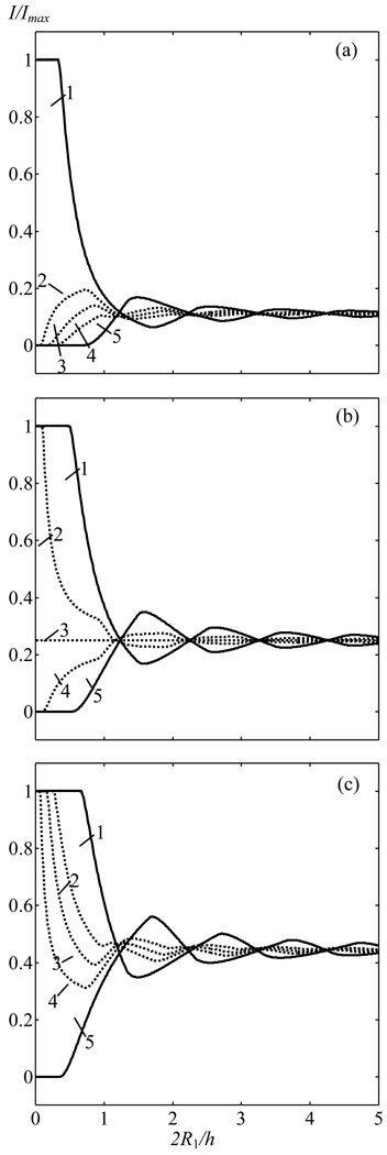
From solution (8), it is seen that a change in the intensity in the focus in the presence of ribs with respect to the case of focusing a beam in a free field depends on three parameters: the position of the beam axis relative to middle of the intercostal space (parameter d), the ratio of the width of the intercostal space to the spatial period of rib structure (a/h), and the number of periods of a grating of ribs that fits the beam aperture (2@R@1/h). Figure 3 shows the dependence of the intensity in the focus on quantity 2R1/h for characteristic values a/h: a = b/2 = h/3 (a), a = b = h/2 (b), and a = 2b =2h/3 (c). Each of the graphs (a)--(b) shows the curves corresponding to various shifts in the beam axis relative to ribs: curve 1 (d = 0) is the case when the radiator axis crosses the middle of the intercostal space, curves 2--4 are intermediate cases d = h/5 (2), h/4 (3), Зh/10 (4), and curve 5 (d = h/2) is the case when the radiator axis intersects the middle of a rib.
Fig. 3.
Dependences of the intensity in the focus on the ratio of the beam aperture to the period of the spatial structure of ribs 2R1/h for various ratios of the dimensions of intercostal spaces and ribs a=b/2 (a), a=b (b) and a=2b (c). Curves 1--5 correspond to various positions of the middle of the intercostal space relative to the beam axis: d=0 (1); h/5 (2); h/4 (3); 3h/10 (4) and h/2 (5). Intensity is normalized to its quantity in the focus in the absence of ribs.
As it is seen from the graphs, when there are less than two spatial periods of ribs within the beam aperture, i.e., 2R1/h≤2, the peak intensity value strongly depends on the value of the shift d. Such a situation occurs in practice when the depth of penetration into tissue is small and there are only one or two ribs on the beam aperture. As the ratio 2R1/h increases, the intensity in the focus tends to some constant value; at 2R1/h > 5, dependence on d becomes insignificant.
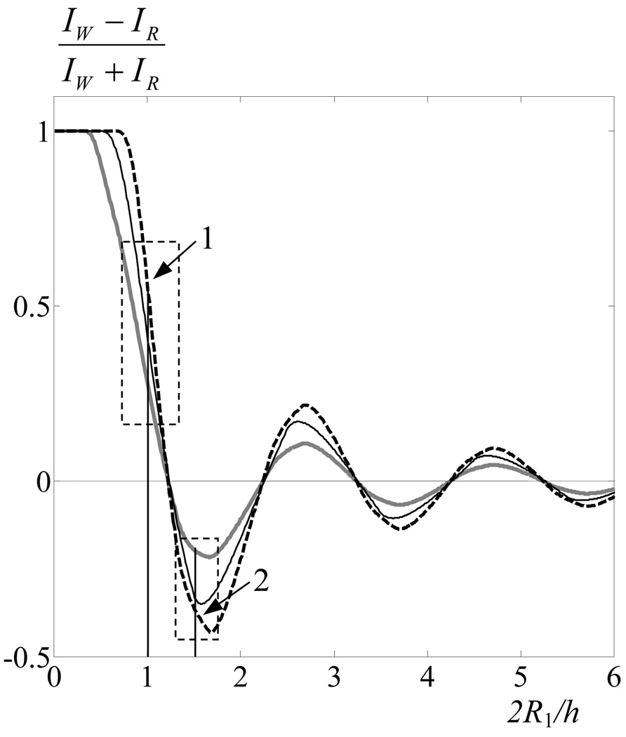
It is also seen that the maximum values of intensity in the focus are achieved when the beam axis intersects either the middle of a rib (IR)) or the middle of the intercostal space (IW) (solid curve in Fig. 3). These cases are analyzed in more detail in Fig. 4, which shows the dependences of the relative difference in intensities (IW−IR)/(IW+IR) on the quantity 2R1/h for various values of a=b/2, a=b and a=2b. Positive values (IW−IR)/(IW+IR) correspond to the situation when intensity is higher if the beam axis intersects the intercostal space; negative values - if a rib is intersected. As is seen from the figure, in intervals of values 2R1/h < 1.2 or 2.2<2R1/h < 3.2, the intensity in the focus will be higher in the case when the axis intersects the middle of the intercostal space. For the values 1.2<2R1/h < 2.2, the intensity in the focus will be higher when the axis intersects the middle of a rib. Thus, if the beam aperture covers less than two periods of the spatial structure of ribs, to achieve the maximum intensity in the focus, it is necessary to carefully select the relative positioning of the radiator and the rib cage.
Fig. 4.
Dependence of the relative difference between the intensities in the focus for the cases when the array axis crosses the middle of a rib (IR) or the middle of the intercostal space (IW) for a=b/2 ( ), a=b (—), a=2b (- -).
An increase or reduction of intensity in the focus when the beam axis is shifted results from a change in the relative area of the beam covered by ribs. So, for example, if the width of a rib and the intercostal space are identical, and the axis passes through the edge of a rib (a = b = h/2, d= a/2= h/4), the area of overlapping a beam by ribs is always identical and is 50%, and the intensity in the focus does not depend on the relation 2R1/h (Fig. 3b, curve 3). If the beam aperture includes several periods of the spatial structure of ribs, the intensity in the focus depends hardly at all on where the beam axis passes (at 2R1/h > 4.2, it is a difference of less than 10%), and the value of intensity as well is proportional to the area of a beam not covered by ribs (33% in the case a = b/2, 50% in the case a = b, and 66% in the case a = 2b). Such a situation is described in [7, 8, 10]; for example, in [10], 2R1/h = 3.5.
If we consider the beam dimensions to be substantially larger than the period of the spatial structure of ribs b and neglect the influence of shift d, we can simplify expression (5) and obtain the intensity distribution in the focal plane along the axis y (in the direction perpendicular to the direction of ribs) in the following form:
| (9) |
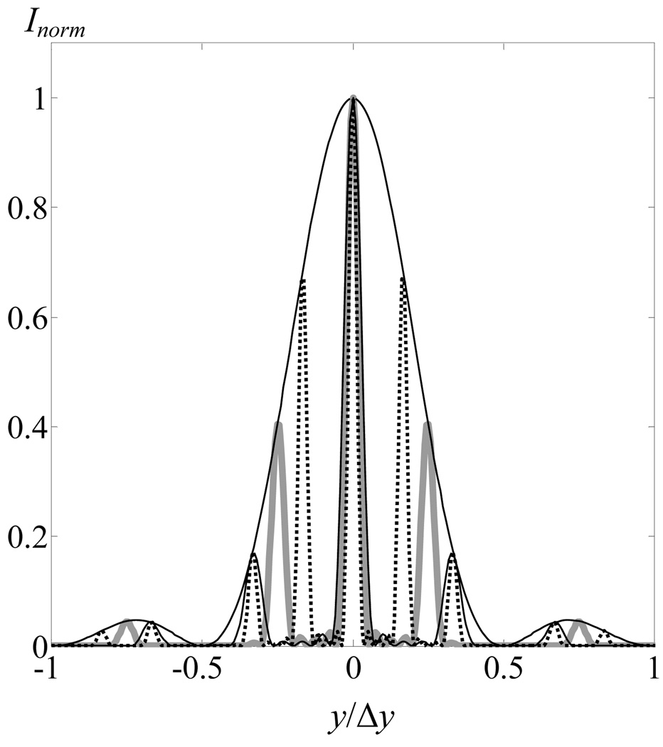
Here notations dy = λ (F − z1)/ h and Δy = 2λ(F − z1)/a were introduced. Solution (9) represents the set of narrow peaks located at distance dy from each other. The widths of peaks are determined by the decay of the Bessel function J1, and the amplitude level is determined by a wider envelope function sinc2, shown in Fig. 5 by the solid line. From expression (9) it is possible to obtain simple analytical estimates for the main parameters of splitting, i.e. the number of secondary maxima, their amplitudes, diameters, and distances between them.
Fig. 5.
Focus splitting in the focal plane after focused ultrasound passes through ribs. Ratio of the dimensions of the intercostal space a and ribs b varied. Cases a = b/2 (--), a = b ( ), a = 2b (—), are shown, in each case the value of intensity is normalized to the maximum value Inorm. The curve of the envelope is determined by the function s sinc2 (2πy/Δy).
As follows from (9), the distance between secondary maxima in the focal plane dy = λ(F − z1)/ h is determined by the wavelength and the ratio of the distance between the rib plane and the focus to the period of the spatial structure of ribs. The diameter of each maximum is determined by the first zeros of the Bessel function δy = 4λ (F − z1)/πR1 and depends on the wavelength and the ratio of the distance between the rib plane and the focus to the radiator aperture. The width of the envelope sinc2 (2πy/Δy) is determined by the directivity diagram of one intercostal space, and the distance between the first zeros is Δy = 2λ(F −z1)/a. Then the number of secondary maxima M situated between the first zeros of the envelope will be determined by the ratio Δy/dy = 2h/a. So, if the dimensions of ribs and intercostal spaces are the same (a=b=h/2), there will be four periods on the width of the envelope; i.e., three maxima arise---in the main focus and one at each side (Fig. 5, gray curve). If the size of the intercostal space is twice smaller than the size of a rib, five maxima will be observed (Fig. 5, points), and if the dimensions of a rib are twice smaller than the size of the intercostal space, only one main maximum will be observed (Fig. 5, dark curve under the envelope).
The ratio of the intensity in the maximum with number m to the intensity in the main maximum is . Here m = 0 corresponds to the main maximum, and the first secondary maxima have indices m=±1. For the cases shown in Fig. 5, I1/I0 = 0.7 at a=b/2, I1/I0 = 0.4 at a=b, and I1/I0 = 0.2 at a=2b.
EFFECT OF FOCUS SPLITTING FOR VARIOUS RADIATORS
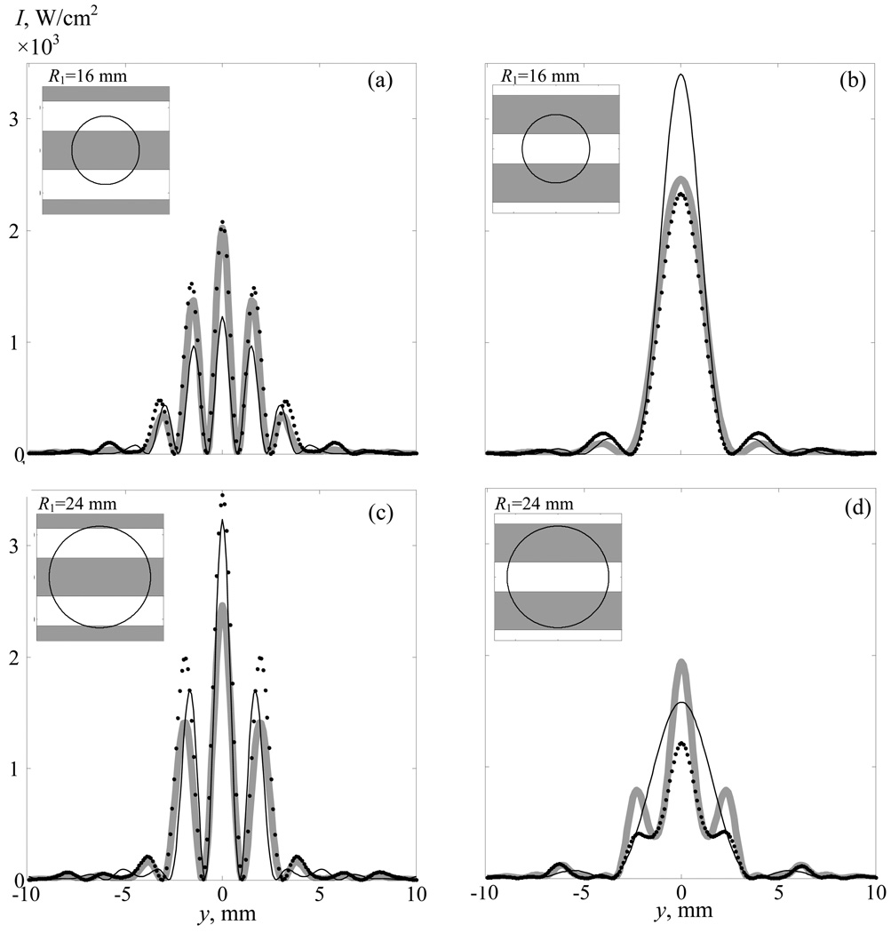
Let us compare now the results obtained within the limits of the approximate analytical model (5) with the results of numerical calculations for more realistic models of a piston radiator and an array. Consider here the limiting cases of ribs of a large size, when there are one to two ribs (2R1/h <2) on the beam aperture, and small size, when there are three to four ribs (2R1/h = 3.5) for a rib cage with dimensions of a = 14 mm and b = 18 mm (a ≈ b). As has been shown above, in the case 2R1/h <2, the type of intensity distribution in the focal plane strongly depends on quantity d characterizing the displacement of ribs perpendicular to the beam axis. This case has been considered in [5], where only one period of the spatial structure of ribs was located on the beam aperture. However, from Fig. 4 it is seen that the distinction between cases 2R1/h =1, as in [5], and 2R1/h = 1.5 is substantial. In the case 2R1/h = 1 (area 1 in Fig. 4), the peak intensity value will be higher if the radiator axis intersects the middle of the intercostal space and the relative difference in the intensities is (IW−IR)/(IW+IR) = 0.47. In the case 2R1/h = 1.5 (area 2 in Fig. 4), in contrast, the peak intensity value will be higher if a rib is intersected and the relative difference in intensities is (IW−IR)/(IW+IR)= −0.34 (Fig. 4).
Let us consider now the field of an array and a piston radiator and compare them with the analytical solution for these two cases. The situation when 2R1/h = 1 corresponds to the position of the rib plane at a distance of z1 = 106 mm, and the situation when 2R1/h = 1.5, at a distance of z1 = 94 mm. In order that, in the absence of ribs, the fields for all three radiators coincided, we use in the analytical solution the parameters chosen above, R1 and I0″. The corresponding curves are shown in Figs. 6a and 6b for 2R1/h = 1 and Fig. 6c and 6d for 2R1/h = 1.5. As it is seen from Fig. 6, the analytical solution well describes the diameter of arising maxima, their position, and the number; a certain distinction is observed only in their amplitude values.
Fig. 6.
Field of the array (•••), field of the piston radiator ( ), and the analytical solution (—) in the focal plane in the presence of ribs when the array axis crosses the middle of a rib d=h/2 (left) and the middle of the intercostal space d=0 (right), (a), (b)--- one period of the spatial structure of ribs (2R1/h =1 is on the beam aperture); (c), (d)--- one and a half periods of the spatial structure of ribs (2R1/h = 1.5 is on the beam aperture).
In the case 2R1/h = 1, if the radiator axis intersects the middle of the intercostal space, a single maximum forms (Fig. 6b). If the center of a rib is intersected, a complex interference pattern of five maxima forms (Fig. 6a), and the peak intensity value decreases. This case has been demonstrated theoretically and experimentally in [5]. Certainly, the situation when the axis passes between ribs (Fig. 6b) is more preferable in clinical use of HIFU. With an insignificant increase in 2R1/h to a value of 1.5, the situation changes substantially and the peak value appears higher for the case when a rib is intersected. The difference is explained by the fact that in the case 2R1/h = 1, the beam area not covered by ribs will be larger if the intercostal space is intersected, and in the case 2R1/h = 1.5, in contrast, the area is larger if a rib is intersected. This is illustrated in the upper left corner of Figs. 6a--6d, where the intensity distributions of a beam in the rib plane are shown schematically. Ribs are shown in gray, intercostal spaces in white; a circle shows the area of intersection of the rib plane by the ultrasonic beam.
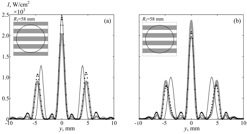
The case of large values of 2R1/h, when on the beam aperture in the rib plane there are 3.5 periods of the spatial structure of ribs, was investigated theoretically and experimentally in [10]. We will consider this case here for the piston radiator, the phased array, and the analytical solution. Corresponding intensity distributions in the focal plane are shown in Fig. 7, where Fig. 7a represents the case when the radiator axis intersects the middle of a rib, and Fig. 7b when the middle of the intercostal space is intersected. It is seen that in both methods of directing the radiator axis, the structure of distributions is very similar. Three intensity maxima are observed: one main maximum, and two secondary ones. Their diameter is identical in all three suggested models and does not depend on whether the radiator axis intersects a rib or the intercostal space. The amplitudes of the main and secondary maxima also change slightly when the beam axis is shifted relative to ribs.
Fig. 7.
Intensity distributions in the focal plane in the presence of ribs for an array (•••), a piston radiator ( ), and the analytical solution (—) when the array axis crosses the middle of a rib d=h/2 (a) and the middle of the intercostal space d=0 (b). Ribs are in a plane z1= 45 mm.
The distances between the maxima calculated in the field of an array and a piston radiator also appeared identical; the analytical solution gives a somewhat smaller, but sufficiently close value. The data shown in Fig. 7 confirms the conclusion made in the discussion of the analytical solution, that if there are more than three to four ribs in the beam aperture, there is no substantial difference in which way to direct the radiator axis---at a rib or at the intercostal space. The structure of the field depending on it hardly changes at all, and the maximum intensity values differ by less than 10%.
FOCUS SPLITTING IN AN IN VITRO EXPERIMENT
In recent experiments with the use of a random therapeutic array, the possibility has been investigated of applying HIFU to ablate soft tissues located behind acoustic obstacles like a rib cage [10]. As a model, phantoms of ribs and samples of the porcine rib cages in vitro were used. The phantom of rib cage contained five strips 5 mm in thickness and 18 mm in width made from the absorbing material Aptflex F48 (Precision Acoustics, Dorchester, UK). The total transmission losses of ultrasound at a frequency of 1 MHz after propagation through this material were 25 dB, and reflection was − 20 dB. The distance between the strips was 14 mm. These dimensions correspond approximately to the typical dimensions of ribs and intercostal spaces in the samples of porcine rib cages that were also used in the experiments. In real samples, the width of ribs was ~16--20 mm, and the distance between them was ~13--16 mm. It is worth noting that the ratio between the dimensions of intercostal spaces and ribs for pigs is much less favorable for propagation of HIFU in comparison with the corresponding characteristic of humans.
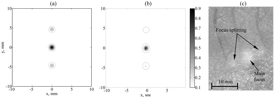
Acoustic power of the array was measured by the radiation force balance method, and the intensity distributions in the focal plane and in the rib plane were obtained with the use of an infrared camera by a technique developed in [16]. Figure 8 shows the intensity distributions in the focal plane of a radiator in water after propagation of ultrasound through the phantom, which was positioned at a distance of z1 = 45 mm from the center of the radiator. Figure 8a shows the intensity distribution obtained in numerical modeling, and Fig. 8b shows the one measured with the IR camera [10]. Each of the distributions is normalized to its maximum value and consists of five contours located every 0.2 Imax from 0.1 to 0.9 Imax.
Fig. 8.
Effect of focus splitting in in vitro experiment. Intensity distribution in the focal plane of a radiator in water after ultrasound propagation through the phantom calculated theoretically (a) and measured in experiment (b). Ablations in soft tissue in vitro (c) at the acoustic power of the array of 120 W and exposure of 5 s.
A characteristic example of ablations induced in soft porcine tissues in vitro after HIFU propagation through phantoms of rib cages is presented in Fig. 8c. The lesions are obtained at the acoustic power of the array of 120 W and duration of 5 s. Focus splitting is well seen in the photograph. The distances between foci, their amplitudes, and dimensions agree well with the parameters calculated using the formulas shown above. These data confirming the ability to ablate tissue after propagation of HIFU through the phantom of a rib cage and to provide acceptable focusing quality demonstrate the feasibility of applying such a method in clinical practice for destruction of tissues behind the ribs.
CONCLUSIONS
In this study, the effect of splitting of the main focus caused by the propagation of focused ultrasound through rib cages is investigated theoretically. The mechanism of this effect is caused by the interference of waves from two or more spatially separated sources, such as intercostal spaces.
This effect is not only of cognitive interest, but also of substantial practical value, since it can influence the safety and efficiency of the ultrasonic method to ablate tissues located behind an acoustic obstacle. The occurrence of secondary intensity maxima along with the main focus can lead to overheating and even destruction of tissues in undesired areas, which should be accounted for in estimating the safety of the ultrasonic treatment. Reduction in intensity in the main maximum in comparison to the case when there are no ribs on the ultrasound propagation path decreases the amplification factors of focusing radiators and, as a consequence, influences the efficiency of ultrasound impact on tissue.
The obtained analytical solution makes it possible to analyze the structure of ultrasound field behind ribs and the parameters of splitting, i.e. the number of foci, their diameter, and distance between them, taking into account the dimensions of the rib cage, position of ribs relative to the radiator, and the radiator parameters. In particular, it is shown that the number of secondary maxima in the focal plane depends only on the ratio of the width of the intercostal space to the period of the spatial structure of ribs. If the intercostal space occupies half of this period, then three foci are observed---the main focus and two secondary intensity maxima; if it occupies one-third, five maxima are observed; and if two-thirds, only one main maximum. The diameter of each maximum coincides with the diameter of the focal spot in the absence of ribs, and the distance between maxima is equal to the result of multiplying the wavelength by the ratio of the distance between the rib plane and the focus to the period of the spatial structure of ribs.
The obtained analytical solution also makes it possible to determine the most appropriate way to direct the radiator axis for arbitrary geometry of bones and with known radiator parameters. It is shown that the intensity in the focus in the presence of ribs in comparison to the case of focusing a beam in a free field depends on three parameters: the position of the radiator axis relative to the middle of the intercostal space, the ratio of the width of the intercostal space to the period of the spatial structure of ribs, and the number of ribs within the beam aperture. The intensity maximum in the focus is reached when the beam area covered by ribs is minimal. To fulfill this condition, it may be expedient to direct the radiator axis not only through the intercostal space, which seems the most natural, but also through a rib.
If the number of ribs is sufficiently large, and less than two periods of the spatial structure of ribs fits the beam aperture, the relative area of overlapping a beam strongly depends on the position of the axis relative to the ribs. If the beam aperture contains more than three to four ribs, the overlapping area is approximately identical for any position of an axis and there is no substantial difference in which way to direct the radiator axis---through a rib or the intercostal space. The structure of the field hardly changes either, and the maximum intensity values differ by less than 10%.
Absorption of ultrasound on the ribs themselves and the effect of focus splitting lead to substantial reduction in the beam energy delivered to the area of the main maximum. When three foci form (identical dimension of ribs and spaces), 50% of the beam energy is lost as ribs are passed, the energy in each secondary maximum is equal to half of the main one, and thus, the energy in the main maximum will be only 25% in comparison to the case of focusing in a free field.
When planning surgical treatments with irradiation through ribs, it is necessary to take into account the effect of focus splitting and reduction in intensity and energy in the main focus accompanying this phenomenon. Since the main objective of ultrasound surgery is usually destruction of relatively large volumes of tissues, the effect of focus splitting described above would hardly be a factor substantially limiting the application of this method. However, in certain cases, for example, when the dimensions of the irradiated volume are small in comparison to the distance between the secondary foci, this phenomenon can be a limiting factor.
ACKNOWLEDGMENTS
The authors are grateful to their colleagues J. Hand (Imperial College, London) and A. Shaw (National Physical Laboratory, Teddington, Great Britain) for the opportunity to carry out joint experiments with the random array, as well as to O.A. Sapozhnikov for useful discussions. The study was partially supported by the grants NSh-4590.2010.2; UMNIK; RFBR 09-02-00066, 09-02-01530; PICS 10-02-91062, and NIH R01EB007643.
Contributor Information
V. A. Khokhlova, Email: sveta@acs366.phys.msu.ru.
S. M. Bobkova, Email: vera@acs366.phys.msu.ru.
L. R. Gavrilov, Email: gavrilov@akin.ru.
REFERENCES
- 1.Bailey MR, Khokhlova VA, Sapozhnikov OA, Kargl SG, Crum LA. Physical mechanisms of the therapeutic effect of ultrasound. Acoust. Phys. 2003;49(4):369–388. [Google Scholar]
- 2.Wu F, Chen WZ, Bai J, Zou JZ, Wang ZL, Zhu H, Wang ZB. Pathological changes in human malignant carcinoma treated with high-intensity focused ultrasound. Ultrasound Med. Biol. 2001;V. 27(№ 8):1099–1106. doi: 10.1016/s0301-5629(01)00389-1. [DOI] [PubMed] [Google Scholar]
- 3.Kennedy JE, Wu F, ter Haar GR, Gleeson FV, Phillips RR, Middleton MR, Cranston D. High-intensity focused ultrasound for the treatment of liver tumours. Ultrasonics. 2004;V. 42(№ 1–9):931–935. doi: 10.1016/j.ultras.2004.01.089. [DOI] [PubMed] [Google Scholar]
- 4.Li F, Gong X, Hu K, Li C, Wang Z. Effect of ribs in HIFU beam path on formation of coagulative necrosis in goat liver. Therapeutic Ultrasound: 5th International Symposium on Therapeutic Ultrasound; AIP Conference Proceedings; Boston, USA; 2006. pp. 477–480. 2005. [Google Scholar]
- 5.Li J-L, Liu X-Zh, Zhang D, Gong X-F. Influence of ribs on nonlinear sound field of therapeutic ultrasound. Ultrasound Med. Biol. 2007;V. 33(№ 9):1413–1420. doi: 10.1016/j.ultrasmedbio.2007.05.001. [DOI] [PubMed] [Google Scholar]
- 6.Liu H-Li, Chang H, Chen W-S, Shih T-C, Hsiao J-K, Lin W-L. Feasibility of transrib focused ultrasound thermal ablation for liver tumors using a spherically curved 2D array: A numerical study. Med Phys. 2007;V.34(№9):3436–3448. doi: 10.1118/1.2759888. [DOI] [PubMed] [Google Scholar]
- 7.Tanter M, Pernot M, Aubry J-F, Montaldo G, Marquet F, Fink M. Compensating for bone interfaces and respiratory motion in high-intensity focused ultrasound. Int. J. Hyperthermia. 2007;V. 23(№ 2):141–151. doi: 10.1080/02656730701209996. [DOI] [PubMed] [Google Scholar]
- 8.Aubry J-F, Pernot M, Marquet F, Tanter M, Fink M. Transcostal high-intensity-focused ultrasound: ex vivo adaptive focusing feasibility study. Phys. Med. Biol. 2008;V. 53:2937–2951. doi: 10.1088/0031-9155/53/11/012. [DOI] [PMC free article] [PubMed] [Google Scholar]
- 9.Bobkova S, Shaw A, Gavrilov LR, Khokhlova VA, Hand JW. Feasibility of HIFU tissue ablation in the presence of ribs using a 2D random phased array. Proceedings ISTU. 2009 Sept 23–26;2009 [Google Scholar]
- 10.Bobkova S, Gavrilov L, Khokhlova V, Shaw A, Hand J. Focusing of high intensity ultrasound through the rib cage using therapeutic random phased array. Ultrasound Med Biol. 2010 doi: 10.1016/j.ultrasmedbio.2010.03.007. (in press) [DOI] [PMC free article] [PubMed] [Google Scholar]
- 11.Gavrilov LR, Hand JW. A theoretical assessment of the relative performance of spherical phased arrays for ultrasound surgery and therapy. IEEE Trans. Ultrason. Ferroelec. Freq. Contr. 2000;V. 41(№ 1):125–139. doi: 10.1109/58.818755. [DOI] [PubMed] [Google Scholar]


