Abstract
The paper presents a robotic method of performing low dose rate prostate brachytherapy under magnetic resonance imaging (MRI) guidance. The design and operation of a fully automated MR compatible seed injector is presented. This is used with the MrBot robot for transperineal percutaneous prostate access. A new image-registration marker and algorithms are also presented. The system is integrated and tested with a 3T MRI scanner. Tests compare three different registration methods, assess the precision of performing automated seed deployment, and use the seeds to assess the accuracy of needle targeting under image guidance. Under the ideal conditions of the in vitro experiments, results show outstanding image-guided needle and seed placement accuracy.
Index Terms: Brachytherapy, IGI, image-guided robot, MR Compatible
I. INTRODUCTION
Prostate cancer is the most common cancer detected in males. It is estimated that approximately thirty three percent of the new cancer cases identified in 2006 will be prostate cancer [1]. Also, it is estimated that prostate cancer will be responsible for ten percent of cancer related deaths in the male population of the United States [1]. Radical surgery or radiotherapy are the most commonly used curative treatment options for prostate cancer [2]. Radiotherapy kills cancer cells by delivering ionizing radiation to the prostate. The radiation can be delivered using external beam irradiation, by high dose radiation sources temporarily delivered percutaneously, or by implanting radioactive pellets (brachytherapy).
Prostate brachytherapy is usually performed under transrectal ultrasound (TRUS) image guidance. The radioactive pellets (seeds, 125I or 103Pd isotopes) are deployed through transperineally inserted needles guided by a template according to a plan [3]–[5]. This pretreatment plan (dosimetry) should ensure that the prostate will receive a radiation dose high enough to destroy the cancer while sparing healthy surrounding tissues as much as possible. Long-term oncological results indicate that brachytherapy is a good treatment option for properly selected patients [6]–[8].
An important factor that influences the outcome of the brachytherapy treatment is the accuracy of seed placement [9]. For example, if a cancer spot does not receive the adequate irradiation, this may lead to relapse of the disease. Accurate seed placement requires a good intra-operative image as well as a good delivery method. Arguably, the best prostate image is provided by MR imaging [10]. Moreover, studies showed promising results in prostate cancer imaging using MR spectroscopy [11]. Therefore, the use of MR imaging for treatment planning and guiding the delivery of therapy could potentially improve clinical outcomes compared to traditional methods
Currently, the needle placement is performed with the use of a template presenting a rectangular pattern of holes used to guide the needles. This allows for placing the needles only at the locations of the holes (usually 5 mm apart) and with parallel needle trajectories. In some patients, this impedes accessing part of the gland due to the interference of the needles with the pubic bone [12]. These problems may be overcome by replacing the needle template with a robotic device for manipulating the needle. Several research groups reported prototypes for robotic assisted brachytherapy of various levels of integration and complexity.
The systems reported for robotic assisted prostate interventions can be classified by the imaging modality used for guidance (i.e., US-guided and MR-guided). An example of an ultrasound-guided system is the one developed by Wei et al. [13]. Their system uses an industrial robot, and a TRUS probe with automated scanning motion. The coordinates of the ultrasound probe with respect to the robot are computed using a calibration procedure. This allows for orienting the robot to any target specified in the ultrasound image. In the first reported prototype, the robot was used only as a needle holder, with the physician being responsible for needle insertion and seed deployment.
MR-guided interventions require needle manipulators that are MR compatible. Building MR robotic systems is a challenging task due to the restrictions imposed by the high intensity magnetic fields of the MR as well as the EM/RF interference that can deteriorate the image signal-to-noise ratio [14], [15]. For example, the ubiquitous electromagnetic actuators may not be used in the MR environment. The use of electricity and some electronic devices in the magnet room may be possible, under certain specifications and shielding.
Several electrically actuated systems for MR-guided interventions were reported. Chinzei et al. developed a MR compatible manipulator for prostate needle interventions [16]. This system automatically positions a needle guide allowing for prostate biopsies and radioactive seed placement under MR guidance in an open MRI scanner. The system is actuated using piezoelectric motors located outside the MR field.
Other MR compatible robotic systems using piezoelectric actuators were reported by Larson et al. [17], Tsekos et al. [18], and by Hempel et al. [19]. The first system was developed for breast interventions and the later two were developed for general chest and abdominal interventions. All three manipulators use piezoelectric actuators to manipulate needle guides for manual needle insertion. The system developed by Hempel et al. was subsequently modified to use pneumatic pistons for actuation and a commercial version is presently being developed (Innomedic GmbH, Germany).
Krieger et al. presented a device for transrectal needle placement in the prostate under MR guidance [20]. Their device is manually operated but uses special localization coils to track the real-time position of the device in the MR image space. The system was successfully tested in animal and human studies at the NIH.
In contrast with the previously reported needle-guide systems, the one presented in this paper is more complex allowing for fully automatic needle insertion and seed deployment under MR guidance. In addition, this fully actuated system is entirely made of nonmagnetic and dielectric materials, and is electricity free exclusively using pneumatics and optics. The system consists of an end-effector mounted on a MR compatible robotic manipulator [21] (MrBot) and it incorporates a new type of pneumatic actuators (PneuStep) developed for fully MR compatible actuators [22]. This paper presents the MR compatible automated seed placement end-effector, image registration and guidance algorithms. The results of an accuracy study for MR-guided seed placement in agar and ex vivo models are also presented. The key novelty of the reported system is the automatic seed deployment under MR guidance.
II. SYSTEM DESIGN
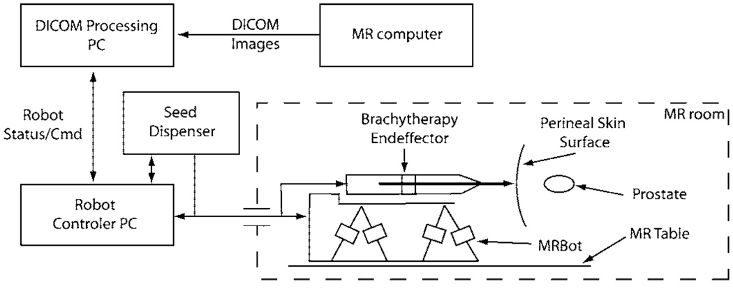
In conventional prostate brachytherapy, a number of needles preloaded with seeds are inserted into the prostate under US guidance. Alternatively, a single needle can be used to place all seeds according to a treatment plan [23]. In this case, the needle is sequentially placed at the desired seed locations and the radioactive seed is deployed through the cannula of the needle. The seeds located on the same needle trajectory can be deployed sequentially in the same needle insertion starting from the deepest location. Therefore, prostate seed placement requires for the robotic system to perform the following tasks: 1) needle orientation; 2) needle insertion; 3) seed deployment. The overall system diagram is presented in Fig. 1. Needle orientation is performed using the MR compatible manipulator, MrBot. Needle insertion and seed deployment are performed by a special brachytherapy end-effector.
Fig. 1.
System Diagram.
A. MR Compatible Manipulator
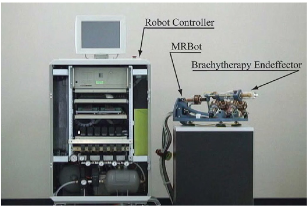
The MrBot robot is a 5 degree of freedom (DOF) (3T+2R) MR compatible manipulator presented in Fig. 2 [21]. It allows for positioning the needle injector end-effector in all directions (3T) and its orientation about two directions normal to the needle axis (2R). Its workspace allows the placement and alignment of the needle towards any prostate target, assuming that initially the robot is roughly aimed towards the prostate.
Fig. 2.
MR compatible automated brachytherapy system components.
The manipulator is pneumatically driven using custom designed MR compatible actuators, PneuStep [22]. The PneuStep is a new type of pneumatic motor, developed especially for MRI compatible robots. This achieves easily controllable precision of motion (0.055 mm in the design used here) by using a stepper motor principle. Position feedback is implemented using fiber-optic sensors. The manipulator is commanded from a control cabinet through a bundle of 6-m-long air hoses and optic fibers. Each PneuStep motor requires 3 air hoses, 4 fibers for incremental encoding, and 2 fibers for a limit switch sensor. During the intervention, the cabinet resides outside the MR room. The cable connecting the control cabinet to the manipulator is passed through the access port of the imager’s room.
B. MR Compatible Automatic Seed Placement System
The seed placement mechanism includes a MR compatible needle injector end-effector and the non MR compatible components that are attached to the control cabinet. Like for the robot, pneumatics and optics are used for the actuation and respectively sensing.
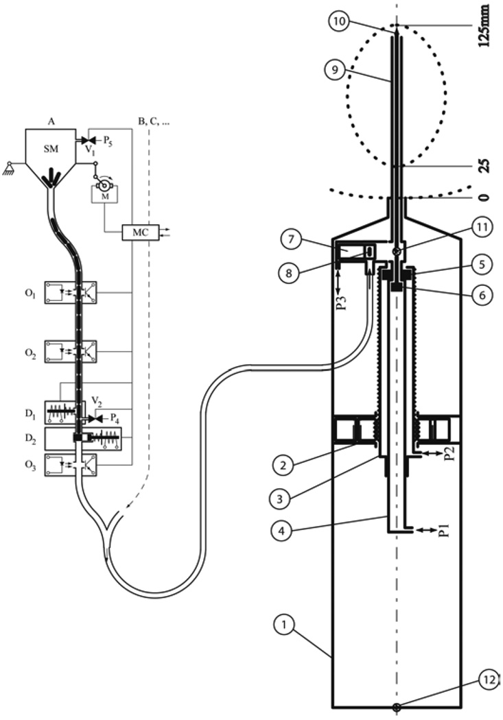
The needle injector was designed using the observation that high speed needle insertion reduces soft-tissue deflection. This was experimentally tested ex vivo and was also reported by other researchers [24]. The injector schematically represented in Fig. 3(b) is composed of two concentric cylinders ➂ and ➃ translated with respect to the case ➀ by the PneuStep motor ➁. The case ➀ is attached to the robot. The motor ➁ allows the adjustment of the insertion depth by shifting needle cylinder and thus its stroke. The needle cylinder ➂ allows for the rapid needle insertion, while the cylinder ➃ allows for maneuvering the stylet of the needle for seed deployment. The insertion speed is be determined by the pressure applied to the piston ➂ through the port P2. Currently, during insertion the applied pressure with a value of 40PSI. This provides an insertion speed of approximately 0.5 m/s. A third pneumatic piston is used for the seed drawer 7. Several holes were placed on the drawer mechanism to allow the possible piston leakage to be discharged in the air. These discharge holes will prevent blood and seeds from being aspired into the mechanism.
Fig. 3.
Seed injector diagram; a) Seed dispenser b) Seed placement end-effector b.1) case; b.2) MR compatible actuator (PneuStep); b.3) needle cylinder; b.4) stylet cylinder; b.5) needle piston; b.6) stylet piston; b.7) seed drawer and cylinder; b.8) seed in the drawer; b.9) needle; b.10) stylet; b.11) seed fiber optic sensor; b.12) retract fiber optic sensor.
The seed dispenser presented in Fig. 3(a) is composed of a jar with a funneled bottom that is shaken using a motor, the motor controller and the seed locking, sending and counting mechanisms. The seeds are preloaded into the jar and they drop into the funnel as the jar is shaken. The funnel proceeds to a tube leading to the sending system. The tube also serves as a sending buffer. Two photoelectric sensors O1 and O2 are used by the controller (MC) to detect the status of the seed column. MC actuates the motor M when O2 is open, and stops the jar shaking when O1 is obstructed. The sensor O3 is used to latch a bistable when a seed passes through. This provides a positive indication that a seed left the seed dispenser. It is possible to connect multiple seed dispenser channels to the same controller and sending tube, allowing for the programmatic use of different types of seeds. In the current implementation, the seed dispenser has two channels. The controller MC is connected to the main computer allowing the user to command the operations required for seed sending.
The procedure for deploying a seed comprises the following steps.
MrBot is moved such that the tip of the needle is at the skin entry point and the injector is aligned towards the target.
The insertion depth is set by positioning the needle cylinder b.3. with the PneuStep motor b.2.
The stylet is inserted into the needle by applying pressure on port b.P1.
The needle is inserted to the desired depth by applying pressure on port b.P2.
The stylet is retracted by applying vacuum on port b.P1.
The seed drawer b.7 is already aligned with the seed transport tube, vacuum being applied on port b.P3.
- Bring one seed from the dispenser:
- The column of seeds in the seed dispenser is blocked by actuating the plunger a.D1. This holds the second seed in the column thus allowing for only one seed to be sent.
- The first seed from the column is released by opening the gate a.D2.
- The seed is sent through the feeding tube to injector by applying pressure on port a.P4. The seed reaches the drawer b.7.
Push the drawer to bring the seed at the axis of the needle by applying pressure on P3.
- Restore the dispenser:
- Release the pressure on P4.
- Lock the seed column by releasing D2 and D1.
Retract the needle one seed length by actuating the PneuStep motor b2.
Slowly push the seed through the needle with the stylet by applying flow limited pressure on P1.
Retract the stylet by applying vacuum on port P1.
Lift the drawer by applying vacuum on port P3.
If there are more seeds to be deployed on the same trajectory then adjust the needle position using the PneuStep 2 and go to Step 7).
Retract the needle by applying vacuum on port P2.
If there are more seeds to be deployed on a different needle path then go to Step 1)
The actuation, seed sending tube, and sensors are included in the 6-m-long bundle of hoses connecting the robot to the control cabinet. The described deployment system was implemented and tested with several thousands of seeds.
The robot-seed injector ensemble was tested by automatically placing patterns of seeds in agar and ex vivo models at arbitrary locations [21]. Then, registration and image guidance algorithms were integrated to place the seeds at targets specified in the image.
C. MRI – Robot Registration and Image Guidance Algorithms
In order to place an instrument to a location selected in a MR image, it is necessary to compute the 6 DOF transformation from the robot space to the image space. The registration is computed using a special marker embedded in the end-effector.
Image to robot registration methods have been previously reported by other authors and are frequently used in computed tomography (CT)-guided interventions. Susil et al. [25] reported a registration method for CT-guided interventions that uses one single image for computing the parameters. The method was generalized by Lee et al. to an algorithm that allows the registration of a plane to a set of lines [26]. The method requires the placement of at least six line markers on the robot. Since the MRI does not raise radiation exposure problems, this one-slice CT method is not as appealing.
Registration methods have been developed purposely for the MR based on the image [27] or by using special coils [20]. While the coil-based registration is accurate and provides real-time data, it is not easily portable from one scanner to another. Image-based registrations are also accurate and imager independent, thus simplifying portability, but are not real-time. This, however, is not an issue because the MrBot is fully encoded.
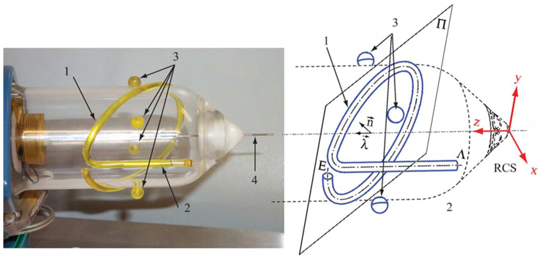
A special marker, fitted to the seed injector end-effector, was developed, Fig. 4. The marker is composed of a line and an ellipse. The intersections of the marker with the planes of the MR slices are used to construct the registration transformation from the robot to the image.
Fig. 4.
MR Registration marker attached to the seed injector; 1) Ellipse, 2) Line, 3) Control Points, 4) Needle.
Three different registration algorithms were implemented and tested. 1) line-ellipse (LE) algorithm. This algorithm automatically segments the image and computes the median point for each trace, then the set of points is matched to the line and the ellipse. 2) line-plane (LP) algorithm. This algorithm is similar with LE, the only difference is that instead of fitting an ellipse the intersection points are fitted to the plane of the ellipse. 3) image-model registration (IMR) algorithm. This registration works in two steps; first, an approximation of the registration is computed using the LP algorithm; second, the transformation computed in the first step is subsequently enhanced using an image to model registration.
The first two algorithms start by binarizing the DICOM acquired MR volume and finding the marker intersections within each image slice. Each image blob is analyzed and the median point is selected. The x and y in slice coordinates and the z position of the slice provide a point in the 3D space. The collection of points is divided in two sets 𝒫L and 𝒫E; 𝒫L containing all the points belonging to the line and 𝒫E containing all the points belonging to the ellipse. These two sets are the primary data for the LE and LP algorithms.
1) Line-Ellipse Algorithm: comprises two main steps. In the first step, the coordinates of the line are reconstructed from the set 𝒫L. This provides 4 DOF of the transformation. The remaining 2 DOF, namely a rotation about the line and the translation along the line, are resolved by fitting the ellipse over the set 𝒫E. The algorithm for computing the transformation from the robot space to the image space is outlined in Appendix A.
2) Line- Plane Algorithm: Line-plane algorithm uses the points 𝒫L to identify a line and the set of points 𝒫E to identify a plane. The line is described by a position vector v1 and a unitary direction vector d1. The plane is identified by a position vector vP and a unitary plane normal nP. The line and plane parameters are identified using a least-squares fitting. Then, taking into account the particular configuration of the marker, the robot coordinate system vectors are expressed in image coordinates as
The rotation matrix from the robot space to the image space becomes
The translation from RCS to ICS is computed by matching the intersection point vi between the ellipse plane and the line in ICS and RCS. The intersection point in ICS, vii, is computed from the two sets of points 𝒫E and 𝒫L. The position of the intersection in RCS, vir is known from the marker construction. The translation between the RCS and ICS is computed as
3) Image-Model Registration: tries to match the 3D marker model over the image. This method uses the registration algorithm implemented by the class ImageToModelRegistration class from the Insight Toolkit [28]. The initial approximation of the registration transform was computed using the LP-algorithm. The class required the implementation of a model to image error metric used in the optimization process. The metric was defined as
where Pixel (p) is the value of the pixel at the position p.
Once the registration information is available the user needs to specify the entry point for the robot and the target point . These two points completely specify the trajectory of the needle and the last seed placement position. The user will also specify the number of seeds and the spacing between seeds. The points are translated in RCS using the registration transformation. Then, are used to compute the desired robot coordinates
The joint positions are computed from TR, αx, αy, and d using the inverse kinematics of the robotic manipulator.
III. RESULTS
A. Image Registration Tests
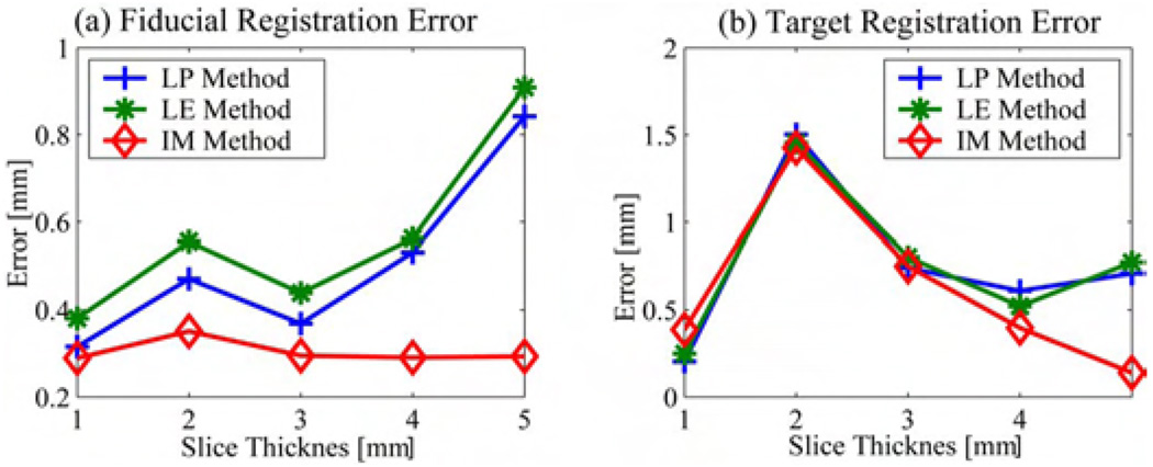
The three registration methods were implemented and tested. The following procedure was carried through. The robot was placed in the MRI scanner. Six volumes were acquired with slice thicknesses of 0.5, 1, 2, 3, 4, and 5 mm with the end-effector in the same position. The registration was performed using the datasets with 1-, 2-, 3-, 4-, and 5-mm slice thickness and the registration transformation was verified using the traces of the control points in the 0.5-mm dataset. The registration error was computed as follows; the registration transformation was used to compute the center of each control point. The result was compared against the control marker center retrieved from the .5-mm dataset. Usually, the registration accuracy is evaluated in terms of fiducial localization error (FLE), fiducial registration error, and the target registration error [29]. The FLE degrades with the slice thickness. Specifically, the localization along the Z-axis of the scanner can not be less than the slice thickness. However, thin slices require a long acquisition time in order to obtain a good signal to noise ration. Therefore, it is desirable to be able to compute an accurate registration with thick slices. The FLE for the verification scan was in the order of half millimeter. Therefore, the spatial localization of the control points is very accurate. The FRE was estimated as the mean localization error for the four control points. Fig. 5(a) shows the FRE computed for the different datasets and for each registration algorithm presented above.
Fig. 5.
Registration Error.
The TRE was estimated assuming that the target is usually placed along the needle at a distance of 125 mm from the RCS. The position of the target was computed using the control points retrieved from the .5-mm scan and by using the registration transformation computed from the other five datasets. Fig. 5(b) presents the estimated TRE corresponding to different registration algorithms used. The graphs show that all three methods performed reasonably well. We noticed that the accuracy deteriorates as the slice thickness increases for LP and LE methods while the IMR method is more robust. However, the computational cost of the IMR method is significantly higher than the others. The decrease in performance with the increase in slice thickness can be explained by the fact that the FLE increases with the slice thickness. Therefore, the user will have the option of choosing the registration method to be used but the default will be set to the LP registration. Our results also show that 3- and 4-mm-thick slices are suitable for registration.
B. Image-Guided Seed Placement Tests
The following tests assessed robots ability to place seeds at random locations in a gel model. The gel used for these tests was purposely prepared such that it is firmer than the regular tissue. This prevented the gel to deflect during needle insertion. The goal of these tests was to test the robot in an ideal setup which is relevant for this development stage. For this the following procedure was used.
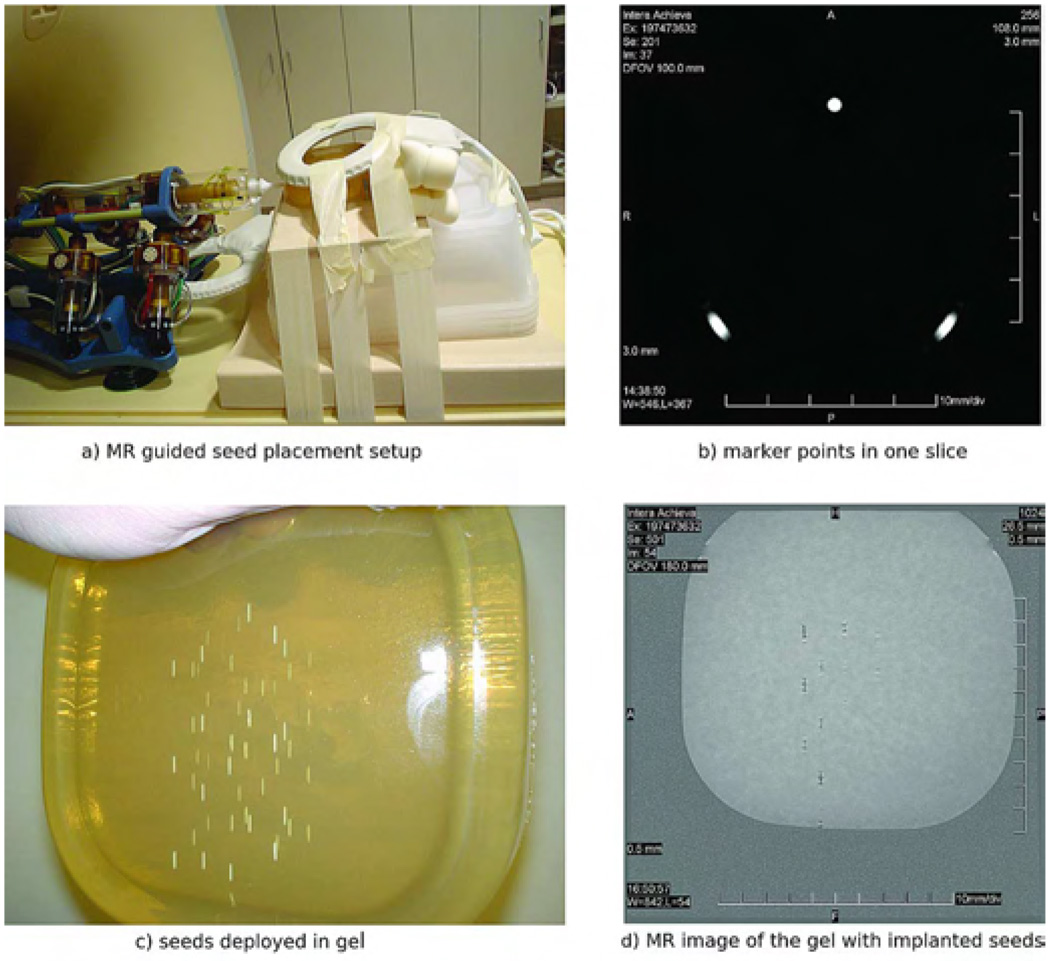
The robot was placed on the MR table together with an agar model as shown in Fig. 6(a).
After an initial scout image with a coarse resolution, the position of the markers was registered with a 3D gradient echo acquisition with the following parameters: repetition time TR/echo time TE = 7.7/2.3 ms; field of view FOV = 100 mm; matrix = 192 × 256; 60 slices with a slice thickness ST = 3 mm; acquired/reconstructed voxel size 0.52 × 0.52 × 3 mm3/0.39 × 0.39 × 3 mm3; acquisition bandwidth BW = 687 Hz/pixel; scan duration dur = 90 s. The robot and the gel were scanned and the registration transformation was computed using the LP algorithm described in Section II-C. Fig. 6(b) shows the image of the marker in an axial MR slice.
Random target positions were chosen in the image. These were uniformly distributed and limited to the workspace of the robot.
Seeds were deployed at the selected targets. Fig. 6(c) presents the agar model with ceramic seeds deployed.
A verification scan was acquired. The localization of the ceramic seeds in the gel was determined with a three dimensional gradient echo acquisition with the following acquisition parameters: TR/TE = 8.0/2.3 ms; FOV = 180 mm; matrix = 512 × 512; 80 slices with a ST = 0.5 mm; acquired/reconstructed voxel size 0.35 × 0.44 × 0.5 mm3/0.18 × 0.18 × 0.5 mm3; BW = 145 Hz/pixel; dur = 336 s Fig. 6(d) illustrates one seed localization slice. In this slice, one can notice that the image artifacts are minimal allowing for accurate seed localization. Custom made ceramic seeds were used for this purpose.
The seeds positions from the control scan were compared against the desired seeds locations.
Fig. 6.
Seed placement setup.
The system was able to deploy all seeds without incidents. This shows that the automatic seed delivery system was properly designed and built.
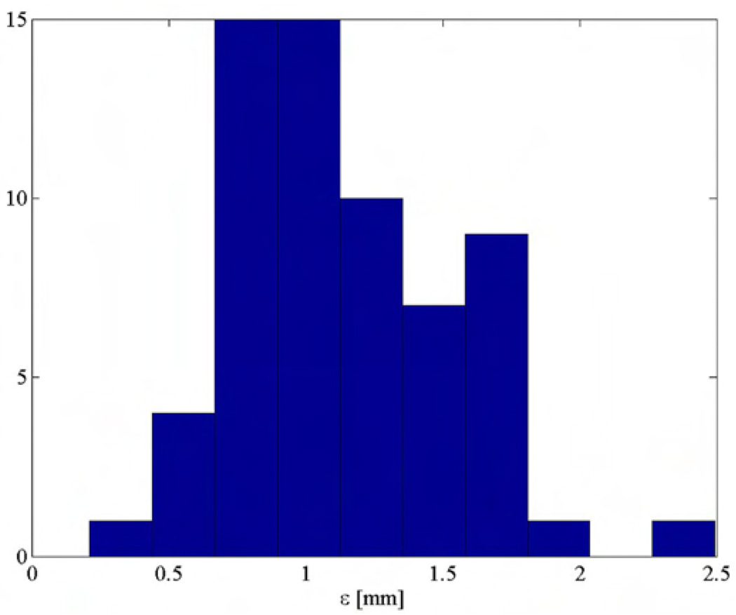
Fig. 7 presents the placement error computed over sixty seeds. The tests showed that the mean seed placement error is less than 1.2 mm. This value cumulates all system errors including imaging, registration, robot positioning, and seed deployment errors. Table I presents the mean values and standard deviations for each component of seed placement error. Table I indicates also that the main error component is in the direction of the needle. This is likely to be caused by seed migration along the needle tract, phenomenon common in brachytherapy procedures. Without this component, the XY positioning error is 0.6 mm mean with 0.2-mm standard deviation.
Fig. 7.
Seed error placement distribution (gel tests).
TABLE I.
Seed Placement Accuracy
| Spatial Componenets | Overall Error [mm] |
|||
|---|---|---|---|---|
| X[mm] | Y[mm] | Z[mm] | ||
| Mean | 0.42 | 0.17 | 0.79 | 1.14 |
| Standard Deviation | 0.30 | 0.38 | 0.64 | 0.41 |
The accuracy computed in these tests can be considered the intrinsic system accuracy, meaning that the system, under ideal conditions, can place seeds within 1.2 mm from the specified target. In living tissues, this accuracy will likely worsen due to soft tissue deflection and seed migration. We conjecture that fast needle insertion will overcome some of the tissue deflection problems. However, the system presented in this paper has an excellent intrinsic accuracy. This justifies the continuation of testing with animal models.
IV. CONCLUSION
The paper presents a robotic system for prostate brachytherapy under MRI guidance. Even though the system is entirely constructed of nonmetallic components and does not use classic actuation methods, it is fully actuated and allows for automated needle manipulation, insertion, and seed deployment. The position of the robot in MR coordinates is computed using a special registration marker and algorithm. The registration algorithm provides sub-millimeter registration accuracy. The mean seed placement accuracy in agar models was approximately 1.2 mm with a 0.4-mm standard deviation. The system shows remarkable accuracy and has the potential to improve the precision of radioactive seeds implantation. Currently, the system is evaluated in animal studies.
Acknowledgments
This work was supported in part the National Institutes of Health (NIH) under Grant CA088232 and in part by the American Foundation of Urologic Disease. The work of A. Patriciu was supported in part by the AFUD/AUAER Research Scholar Program and Dornier MedTech.
Biographies

Alexandru Patriciu (M’00) received the B.Sc. degree in computer science from the University of Craiova, Craiova, Romania, in 1994 and the Ph.D. degree in mechanical engineering from The Johns Hopkins University, Baltimore, MD, in 2004.
From 1994 to 1996, he was a Researcher with the Institute for Computers, Craiova. From 1996 to 1999, he was instructor in the Computer Science Department of the University of Craiova. From 2004 he was AFUD Postoctoral Fellow with the Urology Department, The Johns Hopkins University, Baltimore, MD. His current research interests include medical robotics, image-guided minimally invasive interventions, MR compatible mechatronics and robot control.
Dr. Patriciu is a member of the Association for Computing Machinery and the Society for Urology and Engineering.

Doru Petrisor received the M.S. degree in mechanical engineering from the University of Craiova, Craiova, Romania, in 1988, the Ph.D. degree from the University of Petrosani, Petrosani, Romania, in 2002,
He completed a research fellowship in urology at The Johns Hopkins University, Baltimore, MD. His specialty is CNC manufacturing and design of surgical robotics. Between 1991–1994 he was Assistant Professor at the University of Craiova and Lecturer since 1994. In 2002, he joined the URobotics research group at The Johns Hopkins University.

Michael Muntener was born in Zurich, Switzerland, in October 1970. He received the M.D. degree from the University of Zurich in 1997.
He completed his urological residency in Zurich. He went on to do a Research Fellowship in the Department of Urology at The Johns Hopkins Medical Institutions, Baltimore, MD, where he is currently a Clinical Resident in the Department of Urology. His research interests include urologic oncology as well as robotics in urologic surgery.
Dr. Muntener is a member of the Endourological Society, the Engineering & Urology Society, the Swiss Society of Urology, the German Society of Urology, and the European Association of Urology. He became a Fellow of the European Board of Urology in 2005. He won the best paper award of the Engineering & Urology Society in 2006.

Dumitru Mazilu (M’03) received the B.S./M.S. and Ph.D. degrees in mechanical engineering from the University of Craiova, Craiova, Romania, in 1984 and 1998, respectively.
From 1990 to 1999, he was with the Mechanical Engineering Department, University of Craiova, Craiova, Romania. From 1999 to 2002, he was Postdoctoral Research Fellow with the Urology Department, The Johns Hopkins University, Baltimore, MD, under an American Foundation for Urological Diseases fellowship, where he is currently a Research Associate. His primary research area is medical robotics.

Michael Schär received the diploma in physics and the Ph.D. degree in electrical engineering from the Swiss Federal Institute of Technology (ETH), Zurich, Switzerland, in 2001 and 2005, respectively.
He is currently a Clinical Scientist with Philips Medical Systems, Cleveland, OH, with a Visiting Scientist position with the Department of Radiology, The Johns Hopkins University, Baltimore, MD. The focus of his research activities is on cardiac magnetic resonance spectroscopy and imaging using scanners at a magnetic field of 3 Tesla.

Dan Stoianovici, received the Ph.D. degree in mechanical engineering from Southern Methodist University, Dallas, TX, in 1996.
He completed a medical research fellowship at The Johns Hopkins Medical School, Baltimore, MD in 1998. Currently he is Associate Professor of Urology and Mechanical Engineering and Director of the URobotics Laboratory, The Johns Hopkins Medical School. His specialty is surgical robotics, in particular robotic hardware with extensive hands-on experience. In his career, he developed several robotic systems and devices some of which are presently used in the operating room. His bibliography includes numerous articles, presentations, and 14 patents of invention.
Dr. Stoianovici is the New Technologies section editor for the Journal of Endourology, associate editor for the International Journal of Medical Robotics and Computer Assisted Surgery, consulting editor for the Journal of Robotic Surgery, and co-president of the Engineering and Urology Society.
APPENDIX
LINE ELLIPSE REGISTRATION ALGORITHM
The line is parameterized as
Parameters v1 and d1 are computed from 𝒫L using a classic line fitting method. Then, the registration is fixed up to a rotation about the line and a translation along the line. These two unknowns are solved by fitting the points 𝒫E over the ellipse. The ellipse points are parameterized as
where
θ ∈ [0, 2π] is the ellipse parameter;
δ is the translation along the direction d1 such that v1 + δd1 = vii;
R (v1, v2) ∈ SO (3); ‖v1‖2 = ‖v2‖2 =1 is the rotation matrix that transform in v1 in v2;
e3 = (0 0 1)T;
Rz (α) ∈ SO (3) is the matrix that implements a rotation about the z-axis with the angle α;
ce is the position of the ellipse center in a coordinate system parallel with RCS and centered at vir;
The ellipse is the result of the intersection between a plane and a cylinder of diameter D. The cylinder axis is the robot z-axis and the plane makes a 45° angle with the robot z-axis.
With the previous notations the rotation matrix from RCS to ICS is . Assuming that there are available initial approximations δ0 and α0 for δ, respectively, α, the following algorithm can be used to compute the registration transformation.
Step 1) For each point pj ∈ 𝒫E find the closest point on the ellipse. The vector from an ellipse point to pj is
where R0 = R (e3, d1) Rz (α). Then, the closest ellipse point to pj is u (θj) with
Step 2) If δ = δ0 + δε, α = α0 + αε and αε and δε are small then,
where Skew(v); v ∈ R3 is the skew symmetric matrix associated with the vector v
Therefore, the following equation holds:
This equation can be rearranged in
| (1) |
Equation (1) can be stacked in an over constrained linear system with 2 unknowns and 3nE equations
| (2) |
where
The system 2 is solved in a least-squares sense for δε and αε.
Step 3) The registration transformation is updated using the values computed at Step 2)
If |δε| + |αε| > MinUpd then go back to Step 1); otherwise, follow to Step 4).
Step 4) The registration transformation is
Footnotes
Color versions of one or more of the figures in this paper are available online at http://ieeexplore.ieee.org.
REFERENCES
- 1.Jemal A, Siegel R, Ward E, Murray T, Xu J, Smigal C, Thun MJ. Cancer statistics, 2006. CA Cancer J. Clin. 2006;vol. 56:106–130. doi: 10.3322/canjclin.56.2.106. [DOI] [PubMed] [Google Scholar]
- 2.Naitoh J, Zeiner RL, Dekernion JB. Diagnosis and treatment of prostate cancer. Am. Family Physician. 1998;vol. 57:1531. –+, [PubMed] [Google Scholar]
- 3.Ash D, Bottomley DM, Carey BM. Prostate brachytherapy. Prostate Cancer Prostatic Dis. 1998;vol. 1:185–188. doi: 10.1038/sj.pcan.4500238. [DOI] [PubMed] [Google Scholar]
- 4.Langley SEM, Laing R. Prostate brachytherapy has come of age: A review of the technique and results. BJU Int. 2002;vol. 89:241–249. doi: 10.1046/j.1464-4096.2001.01610.x. [DOI] [PubMed] [Google Scholar]
- 5.Vicini FA, Kini VR, Edmundson G, Gustafson GS, Stromberg J, Martinez A. A comprehensive review of prostate cancer brachytherapy: Defining an optimal technique. Int. J. Radiation Oncol. Biol. Phys. 1999;vol. 44:483–491. doi: 10.1016/s0360-3016(99)00047-4. [DOI] [PubMed] [Google Scholar]
- 6.Sylvester JE, Blasko JC, Grimm PD, Meier R, Malmgren JA. Ten-year biochemical relapse-free survival after external beam radiation and brachytherapy for localized prostate cancer: The seattle experience. Int. J. Radiation Oncol. Biol. Phys. 2003;vol. 57:944–952. doi: 10.1016/s0360-3016(03)00739-9. [DOI] [PubMed] [Google Scholar]
- 7.Stock RG, Cesaretti JA, Stone NN. Disease-specific survival following the brachytherapy management of prostate cancer. Int. J. Radiation Oncol. Biol. Phys. 2006;vol. 64:810–816. doi: 10.1016/j.ijrobp.2005.09.005. [DOI] [PubMed] [Google Scholar]
- 8.Ragde H, Elgamal AAA, Snow PB, Brandt J, Bartolucci AA, Nadir BS, Korb LJ. Ten-year disease free survival after transperineal sonography-guided iodine-125 brachytherapy with or without 45-gray external beam irradiation in the treatment of patients with clinically localized, low to high Gleason grade prostate carcinoma. Cancer. 1998;vol. 83:989–1001. doi: 10.1002/(sici)1097-0142(19980901)83:5<989::aid-cncr26>3.0.co;2-q. [DOI] [PubMed] [Google Scholar]
- 9.Potters L, Morgenstern C, Calugaru E, Fearn P, Jassal A, Presser J, Mullen E. 12-year outcomes following permanent prostate brachytherapy in patients with clinically localized prostate cancer. J. Urol. 2005;vol. 173:1562–1566. doi: 10.1097/01.ju.0000154633.73092.8e. [DOI] [PubMed] [Google Scholar]
- 10.Yu KK, Hricak H. Imaging prostate cancer. Radiologic Clin. N. Am. 2000;vol. 38:59–85. doi: 10.1016/s0033-8389(05)70150-0. [DOI] [PubMed] [Google Scholar]
- 11.Kurhanewicz J, Swanson MG, Nelson SJ, Vigneron DB. Combined magnetic resonance imaging and spectroscopic imaging approach to molecular imaging of prostate cancer. J. Magn. Reson. Imag. 2002;vol. 16:451–463. doi: 10.1002/jmri.10172. [DOI] [PMC free article] [PubMed] [Google Scholar]
- 12.Pathak SD, Grimm PD, Chalana V, Kim Y. Pubic arch detection in transrectal ultrasound-guided prostate cancer therapy. IEEE Trans. Med. Imag. 1998 Oct.vol. 17(no. 5):762–771. doi: 10.1109/42.736032. [DOI] [PubMed] [Google Scholar]
- 13.Wei ZP, Wan G, Gardi L, Mills G, Downey D, Fenster A. Robot-assisted 3D-TRUS-guided prostate brachytherapy: System integration and validation. Med. Phys. 2004;vol. 31:539–548. doi: 10.1118/1.1645680. [DOI] [PubMed] [Google Scholar]
- 14.Chinzei K, Kikinis R, Jolesz FA. MR compatibility of mechatronic devices: Design criteria; Proc. Medical Image Computing and Computer-Assisted Intervention—Miccai’99; 1999. pp. 1020–1030. Lecture Notes in Computer Science. [Google Scholar]
- 15.Stoianovici D. Multi-Imager compatible actuation principles in surgical robotics. Int. J. Med. Robot. Comput. Assist. Surg. 2005;vol. 1:86–100. doi: 10.1002/rcs.19. [DOI] [PMC free article] [PubMed] [Google Scholar]
- 16.Chinzei K, Hata N, Jolesz FA, Kikinis R. MR compatible surgical assist robot: System integration and preliminary feasibility study; Proc. Medical Image Computing and Computer-Assisted Intervention— Miccai 2000; 2000. pp. 921–930. Lecture Notes in Computer Science. [Google Scholar]
- 17.Larson BT, Erdman AG, Tsekos NV, Yacoub E, Tsekos PV, Koutlas LG. Design of an MRI-compatible robotic stereotactic device for minimally invasive interventions in the breast. J. Biomech. Eng.—Trans. ASME. 2004;vol. 126:458–465. doi: 10.1115/1.1785803. [DOI] [PubMed] [Google Scholar]
- 18.Tsekos NV, Ozcan A, Christoforou E. A prototype manipulator for magnetic resonance-guided interventions inside standard cylindrical magnetic resonance imaging scanners. J. Biomech. Eng.—Trans. ASME. 2005;vol. 127:972–980. doi: 10.1115/1.2049339. [DOI] [PubMed] [Google Scholar]
- 19.Hempel E, Fischer H, Gumb L, Hohn T, Krause H, Voges U, Breitwieser H, Gutmann B, Durke J, Bock M, Melzer A. An MRI-compatible surgical robot for precise radiological interventions. Comput. Aided. Surg. 2003;vol. 8:180–191. doi: 10.3109/10929080309146052. [DOI] [PubMed] [Google Scholar]
- 20.Krieger A, Susil RC, Menard C, Coleman JA, Fichtinger G, Atalar E, Whitcomb LL. Design of a novel MRI compatible manipulator for image-guided prostate interventions. IEEE Trans. Biomed. Eng. 2005 Feb.vol. 52(no. 2):306–313. doi: 10.1109/TBME.2004.840497. [DOI] [PMC free article] [PubMed] [Google Scholar]
- 21.Muntener M, Patriciu A, Petrisor D, Mazilu D, Bagga H, Kavoussi LR, Cleary K, Stoianovici D. MRI compatible robotic system for fully automated brachytherapy seed placement. Urology. 2006 doi: 10.1016/j.urology.2006.08.1089. to be published. [DOI] [PMC free article] [PubMed] [Google Scholar]
- 22.Stoianovici D, Patriciu A, Mazilu D, Petrisor D, Kavoussi L. A new type of motor: Pneumatic step motor; IEEE/ASME Trans. Mechatronics; 2006. Feb., pp. 98–106. [DOI] [PMC free article] [PubMed] [Google Scholar]
- 23.Van Gellekom MPR, Moerland MA, Battermann JJ, Lagendijk JJW. MRI-guided prostate brachytherapy with single needle method – A planning study. Radiother. Oncol. 2004;vol. 71:327–332. doi: 10.1016/j.radonc.2004.03.002. [DOI] [PubMed] [Google Scholar]
- 24.Lagerburg V, Moerland MA, Konings MK, van de Vosse RE, Lagendijk JJW, Battermann JJ. Development of a tapping device: A new needle insertion method for prostate brachytherapy. Phys. Med. Biol. 2006;vol. 51:891–902. doi: 10.1088/0031-9155/51/4/009. [DOI] [PubMed] [Google Scholar]
- 25.Susil RC, Anderson JH, Taylor RH. A single image registration method for CT-guided interventions; Proc. Medical Image Computing and Computer-Assisted Intervention—Miccai’99; 1999. pp. 798–808. Lecture Notes in Computer Science. [Google Scholar]
- 26.Lee S, Fichtinger G, Chirikjian GS. Numerical algorithms for spatial registration of line fiducials from cross-sectional images. Med. Phys. 2002;vol. 29:1881–1891. doi: 10.1118/1.1493777. [DOI] [PubMed] [Google Scholar]
- 27.Krieger A, Metzger G, Fichtinger G, Atalar E, Whitcomb LL. A hybrid method for 6-DOF tracking of MRI-compatible robotic interventional devices. presented at the 2006 IEEE International Conf. Robotics and Automation; Orlando, FL. 2006. [Google Scholar]
- 28.Ibanez L, Schroeder W, Ng L, Cates J. The ITK Software Guide. Clifton Park, NY: Kitware Inc.; 2003. [Google Scholar]
- 29.Fitzpatrick JM, West JB, Maurer CR. Predicting error in rigid-body point-based registration; IEEE Trans. Med. Imag; 1998. Oct., pp. 694–702. [DOI] [PubMed] [Google Scholar]


