Abstract
Investigations are reported on the x-ray scintillation and imaging application of CdTe quantum dots (QDs) and their polymer nanocomposites. Aqueous CdTe QDs with emissions ranging between 510 and 680 nm were prepared and incorporated into polyvinyl alcohol or polymethyl methacrylate polymer matrices. The x-ray luminescent properties were evaluated and a resolution of 5 lines∕mm was obtained from the nanocomposite films. Additionally, the fast decay time, nonafterglow, and superior spectral match to conventional charge coupled devices, show that CdTe QD nanocomposites have high promise for x-ray imaging applications.
High-performance x-ray phosphor screens are a key device component for applications such as x-ray crystallography and mammography. For example, the current generation of charge coupled devices (CCDs) based x-ray crystallography detectors are mosaic arrays of individual modules, each consisting of a phosphor screen, to convert incident x-rays to light, a fiber-optic taper to couple the light into a CCD sensor, and the CCD, which converts the light into an electronically readable format.1, 2 However, these x-ray detectors are still not as fast, sensitive, efficient, or have high enough resolution as required by some applications and existing limitations restricts their usefulness in many biological and medical applications. In order to improve the performance of these detectors, x-ray phosphor screens with excellent properties including: high stopping power, high spatial resolution, very fast decay times, minimum afterglow, detector spectral match, and excellent x-ray conversion efficiency are required.
In this letter, CdTe quantum dot (QD) based polymer nanocomposites were studied for x-ray scintillation and imaging applications. QD nanomaterials can be advantageous for x-ray applications compared to traditional phosphors. Current x-ray phosphor screens are made using micron-sized powder phosphors such as Gd2O2S:Tb, ZnSe:Cu,Cl, or CsI:Tl, which are efficient and bright x-ray converters.3 They provide good results with regards to efficiency (ratio of visible light output to x-ray absorption), stopping power (x-ray absorption efficiency), and time response (decay time and afterglow). However, large-sized phosphor particles give rise to a great deal of scatter, which limits their spatial resolution (minimum distinguishable features in the image). There is ample theoretical argument to suggest that nanometer-sized particles, such as QDs, in a transparent polymer-matrix screen will exhibit significantly higher spatial resolution than micron-sized phosphor particles.4, 5 In addition, the fast decay time and nonafterglow features of QDs will ensure faster time response than that of existing powder phosphors. Also, QDs can be made from high-Z and high density compounds such as CdTe, CdHgTe, PbSe, and PbTe to increase stopping power relative to that of low-Z and less-dense phosphor materials. Moreover, the narrow emission band of QDs can be tuned such that their visible light emission spectrum exactly matches the peak spectral sensitivity of CCD sensors to improve the overall detection efficiency.
With regard to x-ray conversion efficiency, QD materials are also promising from the viewpoint of band gap (Eg) energy. The x-ray conversion efficiency of phosphor materials is higher for small band gap materials than for large band gap ones, because the energy required to create one electron-hole pair or one emitting photon is at least equal to the host band gap Eg. Although the x-ray excitation mechanism in QD is still not clear, charge carrier multiplication has been observed and reported for high energy UV excited QD.6, 7 For example, seven excitons and photons can be generated in PbSe QD by exciting with one UV photon with energy 7.8 times higher than the QD band gap energy.7 If the energy of the incident x-ray photon is Ex-ray, the quantum gain geh of the phosphor is given by the following:8
where β is an inefficiency parameter which is larger than unity due to energy loss from phonon scattering; ηeh is the fraction of electrons and holes that recombination at active luminescent centers; QEl is the quantum efficiency of photon generation from excited centers. The smaller the host band gap, the higher the gain of the phosphor due to formation of more electron-hole pairs. For QDs, their band gap is strongly dependent on the particle size. Since the particle size can be controlled by manipulating the crystal growth conditions, the band gap of QDs can be tuned to produce smaller band gap QD materials that emit red to infrared light. This matches well to the spectral sensitivity of CCD sensors, which typically are most sensitive in the red and near-infrared regimes with peak efficiency about 1.8 eV. Thus, each x-ray photon generates more electron-hole pairs and thus more photons in a small band gap QD, compared to conventional phosphors with larger band gaps, and this light is more efficiently captured by CCD sensors.
Recently, research interests have emerged regarding what QDs can do for scintillation applications. Some early demonstrations of QD scintillators have been reported when irradiated with low energy gamma ray but not x-rays.9 For example, CdSe∕ZnS core∕shell QDs suspended in Vycor glass plates yielded a strong response under 59 keV gamma ray irradiation. A photon yield of 70 600 was predicted at 1 MeV compared to the typical value of 40 000 obtained with a standard NaI:Tl detector, suggests a high efficiency and better resolution is possible with QD based scintillators. Another example that has been investigated is radiation detection using a spin-coated QD∕organic polymer composite.10
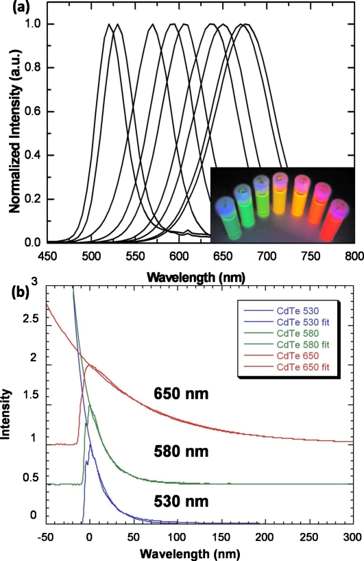
In this letter CdTe QDs with controlled particle size and emission wavelength were prepared using a synthesis technique as reported by Zhang et al.11 Colloidal CdTe solutions were synthesized by adding freshly prepared NaHTe solution to N2-saturated Cd(ClO4)2 solutions in the presence of mercaptopropionic acid (MPA) as the stabilizing agents and water as the solvent. The solutions were then heated to the boiling temperature and refluxed for different times to obtain a controlled dot size. A series of MPA-capped CdTe QDs were synthesized in water with controlled emission colors from green to red as shown in Fig. 1a. Photoluminescence (PL) measurements were conducted using a Cary Eclipse Fluorescence Spectrometer. A shift of the PL peak from 520 to 680 nm occurs with increasing refluxing times indicating an increase in particle size during the growth stage. For 680 nm emitting CdTe QDs, the peak emission matched its spectral sensitivity of a typical CCD sensor very well and thus higher detection efficiency was expected compared to blue and green emitting particles. While the PL emission wavelength was controlled by the particle size due to quantum confinement effects, the PL efficiency was controlled by the surface passivation. Surface coverage with Cd–thiol complexes contributed greatly to both PL enhancement and the stability of the resulting particles.
Figure 1.
(a) Normalized PL spectra for a series of MPA-capped CdTe QDs shows peak emissions between 520 and 680 nm; the inset shows the luminescence image of various CdTe QDs under 365 nm UV light excitement. (b) Measured and fitted exponential decay from CdTe QDs emitting at 530 nm, 580 nm, and 650 nm with decay time of 19 ns, 21 ns, and 87 ns, respectively.
The time response of an imaging system is affected by the luminescence decay time of the phosphor. Slow response and a long decay time can seriously slow down the experimental readout of a CCD imaging system or degrade image quality by causing blurring of the acquired image. Therefore, for high resolution x-ray imaging applications, the fastest possible phosphor decay time is preferred. The PL decay curves of CdTe QDs with different size and emission peaks were investigated and shown in Fig. 1b. CdTe QDs emitting at 530 nm, 580 nm, and 650 nm exhibited decay time of 19 ns, 21 ns, and 87 ns, respectively. This is three orders of magnitude faster than ZnSe:Cu,Cl, which exhibits a 1∕e decay time of 8.9 μs; and five orders of magnitude faster than Gd2O2S:Tb with a decay time of 470 μs. In addition to the decay time, another very important temporal property of x-ray phosphors which affects image resolution is the afterglow, especially when used in a scanning imaging system. For CdTe QDs, no afterglow was observed. Therefore, the fast decay time and nonafterglow features of QDs will ensure faster time response than that of existing powder phosphors.
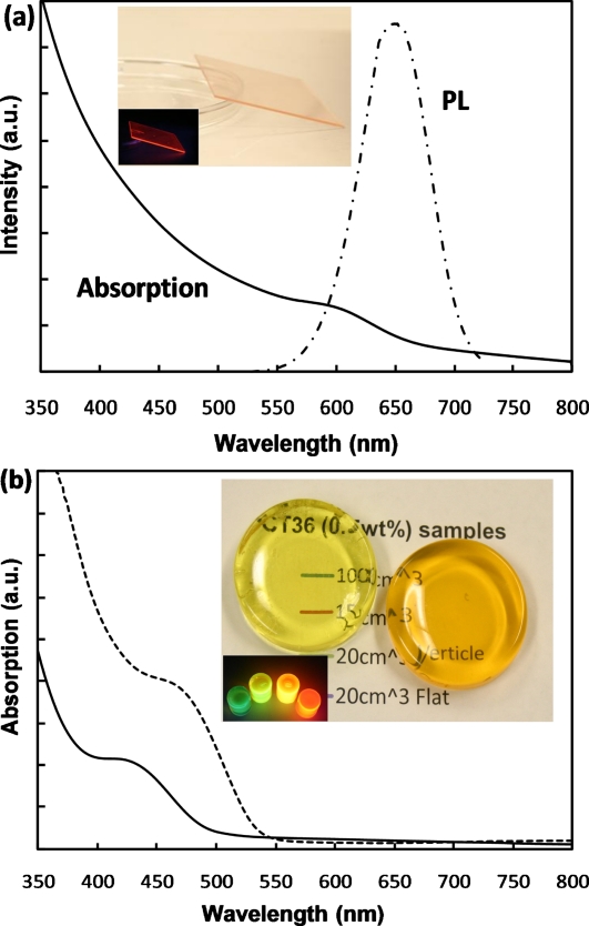
To investigate the x-ray imaging application, the synthesized CdTe QDs were incorporated into a polymer matrix to make a nanocomposite film with QD loading between 0.1 and 10 wt %. By mixing the QD solution with a water soluble polymer, polyvinyl alcohol (PVA), a well-dispersed composite solution was obtained. The concentration of aqueous QD solutions were easily controlled by first precipitating the synthesized QDs using nonsolvent 2-proponal, following which the dried QD powders were redispersed in DI water to obtain a high concentration. The viscosity of the solution was controlled by the proportion of polymer content in the solution. This solution was spin-coated on a glass substrate, following which the solvent was evaporated, thus yielding a nanocomposite film. For example, a transparent 2 wt % CdTe∕PVA film with thickness of ∼30 μm is shown in the inset of Fig. 2a. The PL spectrum shows an emission peak at 650 nm from the encapsulated CdTe QDs. Absorption measurements were performed using a Cary 5000 UV-Vis-NIR Spectrophotometer and indicated the first excitonic absorption peak at ∼600 nm from the QDs.
Figure 2.
(a) Absorption and PL spectra of a 2 wt % CdTe/PVA nanocomposite film deposited on a glass substrate; the inset shows images of the sample under room light and 365 nm UV light. (b) Absorption spectra of a 0.2 wt % CdTe (510 nm)/PMMA and a 0.5 wt % CdTe(565nm)/PMMA nanocomposite sample; the highly transparent samples were shown in the inset photograph. Samples with various emission colors under a 365 nm UV lamp were also shown.
The transparency of phosphor screen is critical for high spatial resolution x-ray imaging. By direct mixing QD solution with PVA, the transparency of the obtained nanocomposite film decreased when the film thickness and QD concentration increased due to segregation of QDs. As shown in Fig. 2a, the linear increase in absorption from 800 to 650 nm was actually caused by the scattering from segregated QDs. To obtain a highly transparent nanocomposite, CdTe-polymethyl methacrylate (PMMA) composite samples were also prepared using a bulk polymerization method reported by Zhang et al.12 To avoid agglomeration and maintain transparency, a polymerizable surfactant, octadecyl-p-vinylbenzyl dimethylammonium chloride (OVDAC), was used to link to the surface ligands of the nanoparticles to the polymer matrix and to immobilize them during the polymerization process. In this process, OVDAC was first used to extract the QDs from the water solution into a methyl-methacrylate monomer. Then the monomer solution was polymerized in an oil bath at 65 °C for ∼20 h using 0.1 wt % 2,2′-azobisisobutyronitrile as the initiator. Figure 2b shows the image of several transparent CdTe-PMMA composite samples with thickness between 10 and 20 mm. The inset shows their various emission colors stimulated by a 365 nm UV lamp. The samples are transparent to light with wavelengths equal or longer than the emission color. A sufficient density of nanoparticles must be incorporated into the polymer matrix so that the x-ray detection efficiency of the phosphor screen is adequate for the task.
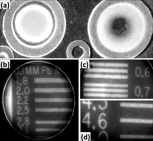
Both QD solution and nanocomposite samples were investigated for x-ray scintillation and imaging applications. The QD solutions were loaded into a tubular container and placed into the x-ray imaging machine for x-ray excitation. The emitted light from the QD samples were recorded with a CCD detector. Figure 3a shows the x-ray image of a synthesized CdTe and a commercial CdSe QD (from Evident Technologies, Inc.) solution. The brighter image from the 650 nm emitting CdTe QD sample at the left side indicated a higher detection efficiency compared to the 540 nm emitting CdSe QD sample with similar concentration. The intrinsic higher stopping power of CdTe compared to CdSe due to larger Z number (50∕41) and higher density (5.86∕5.66 g cm−3) may contribute to the brighter x-ray luminescence. It was also observed for both the CdTe and CdSe samples that with increasing the QD concentration, the x-ray luminescence intensity increased due to the increase in stopping power. Figures 3b, 3c, 3d show the imaging resolution of a CdTe QD∕PVA nanocomposite film. A resolution of 5 lines∕mm could be resolved approximately twice that of an optimized commercial Gd2O2S:Tb screen with a resolution of 2.8 lines∕mm. Further improvements in the performance of this material will, therefore, be of great benefit in enhancing the sensitivity of x-ray detectors and allowing higher resolution imaging systems.
Figure 3.
(a) X-ray image of CdTe and CdSe QD solution samples in containers (left: CdTe; right: CdSe). [(b)–(d)] X-ray imaging resolution study on a CdTe∕PVA nanocomposite film; a 0.1 mm thick Pb mask was used. (b) Area with resolution of 1.8–3.1 lines∕mm. (c) Low resolution area with 0.6 lines∕mm. (d) Enlarged image of higher resolution area with 4.3–5.0 lines∕mm.
In conclusion, CdTe QDs and their polymer nanocomposites were studied for x-ray scintillation and imaging applications. The excellent x-ray luminescence results including: high resolution, fast decay, nonafterglow, high stopping power, and superior spectral match to the CCD detector, indicated that CdTe nanocomposite is a promising nanophosphor candidate for x-ray imaging applications.
Acknowledgments
This research was supported by the National Institute of Health under Contract No. NIH R43RR026166-01, with additional support from Radiation Monitoring Devices, Inc. and the Georgia Institute of Technology.
References
- Ealick S. E., Nat. Struct. Biol. 5, 620 (1998). 10.1038/1314 [DOI] [PubMed] [Google Scholar]
- Ban N., Nissen P., Hansen J., Moore P. B., and Steitz T. A., Science 289, 905 (2000). 10.1126/science.289.5481.905 [DOI] [PubMed] [Google Scholar]
- Phosphor Handbook, edited by Shionoya S. and Yen W. (CRC, Boca Raton, Florida, 1999). [Google Scholar]
- McKigney E. A., Del Sesto R. E., Jacobsohn L. G., Santi P. A., Muenchausen R. E., Ott K. C., McCleskey T. M., Bennett B. L., Smith J. F., and Cooke D. W., Nucl. Instrum. Methods Phys. Res. A 579, 15 (2007). 10.1016/j.nima.2007.04.004 [DOI] [Google Scholar]
- Milbrath B. D., Peurrung A. J., Bliss M., and Weber W. J., J. Mater. Res. 23, 2561 (2008). 10.1557/jmr.2008.0319 [DOI] [Google Scholar]
- Schaller R. D., Sykora M., Pietryga J. M., and Klimov V. I., Appl. Phys. Lett. 87, 253102 (2005). 10.1063/1.2142092 [DOI] [Google Scholar]
- Schaller R. D., Sykora M., Pietryga J. M., and Klimov V. I., Nano Lett. 6, 424 (2006). 10.1021/nl052276g [DOI] [PubMed] [Google Scholar]
- Inoue M., J. Appl. Phys. 55, 1558 (1984). 10.1063/1.333414 [DOI] [Google Scholar]
- Létant S. E. and Wang T. -F., Nano Lett. 6, 2877 (2006). 10.1021/nl0620942 [DOI] [PubMed] [Google Scholar]
- Campbell I. H. and Crone B. K., Adv. Mater. (Weinheim, Ger.) 18, 77 (2006). 10.1002/adma.200501434 [DOI] [Google Scholar]
- Zhang H., Wang L., Xiong H., Hu L., Yang B., and Li W., Adv. Mater. (Weinheim, Ger.) 15, 1712 (2003). 10.1002/adma.200305653 [DOI] [Google Scholar]
- Zhang H., Wang C., Li M., Zhang J., Lu G., and Yang B., Adv. Mater. (Weinheim, Ger.) 17, 853 (2005). 10.1002/adma.200401303 [DOI] [Google Scholar]


