

Abstract
Many aquatic organisms swim by means of an undulating fin. These undulations often form a single wave travelling from one end of the fin to the other. However, when these aquatic animals are holding station or hovering, there is often a travelling wave from the head to the tail, and another moving from the tail to the head, meeting in the middle of the fin. Our study uses a biomimetic fish robot and computational fluid dynamics on a model of a real fish to uncover the mechanics of these inward counter-propagating waves. In addition, we compare the flow structure and upward force generated by inward counter-propagating waves to standing waves, unidirectional waves, and outward counter-propagating waves (i.e. one wave travelling from the middle of the fin to the head, and another wave travelling from the middle of the fin to the tail). Using digital particle image velocimetry to capture the flow structure around the fish robot, and computational fluid dynamics, we show that inward counter-propagating waves generate a clear mushroom-cloud-like flow structure with an inverted jet. The two streams of fluid set up by the two travelling waves ‘collide’ together (forming the mushroom cap) and collect into a narrow jet away from the cap (the mushroom stem). The reaction force from this jet acts to push the body in the opposite direction to the jet, perpendicular to the direction of movement provided by a single travelling wave. This downward jet provides a substantial increase in the perpendicular force when compared with the other types of fin actuation. Animals can thereby move upward if the fin is along the bottom midline of the body (or downward if on top); or left–right if the fins are along the lateral margins. In addition to illuminating how a large number of undulatory swimmers can use elongated fins to move in unexpected directions, the phenomenon of counter-propagating waves provides novel motion capabilities for systems using robotic undulators, an emerging technology for propelling underwater vehicles.
Keywords: fish swimming, fin propulsion, wake structure, fluid dynamics, particle image velocimetry
1. Introduction
Many groups of aquatic organisms undulate portions of their body to swim, such as margins of the body mantle in the case of cuttlefish or elongated fins on fish. In the case of elongated fins on bony fish, there are three typical configurations. First, an elongated anal fin, which can run most of the body length along the belly, as shown in figure 1a. Second, an elongated dorsal fin, which again runs most of the length of the body along the midline of the back, as in the African aba aba (Gymnarchus niloticus) and deep sea oarfish such as the giant oarfish (Regalecus glesne). Third, a combination of dorsal and anal fins, as seen in triggerfish. These fins are moved with a variety of patterns, but during steady swimming one common pattern is a single, continuous travelling wave from one end of the fin to the other [1,2]. In other cases, when the fish is not swimming continuously in one direction or is moving slowly, more than one wave can be simultaneously present on different elongated fins on the body. For example, Blake [1] reported that triggerfishes (Rhinecanthus aculeatus and Odonus niger) hover by propagating waves from anterior to posterior on the dorsal fin and in the opposite direction on the anal fin.
Figure 1.

The black ghost knifefish (Apteronotus albifrons) and robotic knifefish. (a) Photograph courtesy of Per Erik Sviland. (b) Video sequence of oppositely travelling waves during A. albifrons hovering. The translucent strips connect across the peaks of two counter-propagating travelling waves. The white lines show the bottom edge of the ribbon fin. (c) The robotic knifefish: a physical model to study undulatory fin propulsion. (d) Bottom view of the robotic knifefish showing the peaks of two counter-propagating travelling waves and the bottom edge of the ribbon fin.
To ground our study, we focus on the undulatory ribbon fin of one type of South American weakly electric knifefish, the black ghost Apteronotus albifrons (figure 1a). It is one of approximately 170 species of weakly electric knifefish [3], all of which swim in a similar fashion. The black ghost knifefish hunts and navigates in complete darkness through the geometrically complex environment of Amazon Basin rivers. There are two key capabilities that enable this behaviour. First, the fish can sense objects in all directions around the body [4] through an active sensing system based on self-generated discharges of electricity. Second, the fish propels itself in a manner that facilitates rapid movement in many directions, and rapid changes in direction of movement, such as sub-second reversals in swimming direction [5,6]. Propulsion is accomplished by means of undulating an elongated fin on the belly that runs nearly the entire length of the fish. Typically, during forward or backward swimming, the undulations mostly proceed from one end of the fin to the other. However, as shown in figure 1b and the electronic supplementary material, movie S1, the black ghost can also send a series of travelling waves from the head to the tail, simultaneous with a series of travelling waves moving from tail to head, meeting around the middle of the fin. We refer to this style of ribbon fin movement as ‘inward counter-propagating waves’. The fish exhibits inward counter-propagating waves typically when it is hovering–staying stationary with active stabilization against perturbations.
Using high-fidelity computational fluid dynamics on a fish model and digital particle image velocimetry (DPIV) to capture the flow structure around a robotic bio-mimetic knifefish, we show the underlying mechanical principles of counter-propagating waves. In addition, we compare the fluid structure and force generated by the robotic fish using inward counter-propagating waves against standing waves, unidirectional waves and outward counter-propagating waves (i.e. oppositely travelling waves generated from the middle of the fin towards the head and tail of the fish). Even though standing waves or outward counter-propagating waves have not been reported in fish swimming, this comparison sheds light on the mechanical advantage of inward counter-propagating waves. The computational fluid dynamics simulations were matched to the Reynolds number (number that quantifies the ratio between inertial to viscous forces) of A. albifrons, and provided the three-dimensional structure of the flow. Subsequent experiments with the biorobotic knifefish were used to obtain experimental measurement of the flow structures and forces for a variety of travelling wave kinematic regimes established in prior studies of ribbon fin kinematics [2,6]. Although our study uses the black ghost, the principles we demonstrate have broad applicability to understanding the phenomenon of counter-propagating waves along undulatory fins, a mechanism that is likely to be widespread among aquatic animals that swim by undulating their ventral, dorsal or lateral fins. Indeed, even in a very rare deep sea video of the giant oarfish (R. glesne), a fish that can grow to 11 m [7], counter-propagating waves can be clearly seen along the dorsal fin [8].
2. Material and methods
Figure 2 shows a model of the black ghost knifefish along with the Eulerian reference frame (x, y and z) and the body reference frame (surge, heave and sway). Also shown are four key fin variables: fin length (Lfin), fin height (hfin), angular deflection (θ) and lengthwise coordinate frame for the fin (xfin).
Figure 2.

Perspective and bottom view of the fish model used for the computational fluid dynamics. The fin length (Lfin), the fin height (hfin), the angular fin deflection (θ), the Eulerian reference frame for the fluid simulations (x, y, z) and the fish body frame (surge, heave and sway) are also shown.
2.1. Behavioural observations and fish density measurement
Observations of black ghost knifefish (A. albifrons) hovering were obtained while the fish was in stationary refuge. The refuge was used to facilitate the positioning of the fish with respect to the camera, as the fish prefers confined spaces (the fish stays within the refuge without any type of training). The length of the fish was approximately 12.6 cm. The refuge was made of transparent plexiglas and had dimensions of 15 × 3.8 × 5.2 cm in the x, y and z directions, respectively. The motion of the fish was recorded with a high-speed camera (Casio Exilim, Shibuya-ku, Tokyo, Japan) at 300 frames s−1. The water tank for the experiment had dimensions of 50 × 24.75 × 28.5 cm in the x, y and z directions, respectively.
The density of the fish was estimated by anaesthetizing three fish with a 100 ppm solution of tricane methanesulphonate (MS-222, Western Chemical Inc, Ferndale, Washington, USA), then weighing them and measuring the water volume displaced by their bodies. The delay between the administration of MS-222 and the volume measurement was approximately 5–10 min long.
2.2. Computational fluid dynamics simulation
An accurate cast of A. albifrons from a prior study [9] was used to obtain the fish model for the computational simulation (figure 2). The fish model was 12.6 cm long with a ribbon fin length, Lfin, of 8.7 cm, and a fin height of 0.9 cm. Although the ribbon fin height on actual fish tapers towards the front and rear part for the fin, we considered a constant fin height.
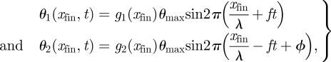
Based on empirical observations of hovering and by qualitative inspection of our behavioural data, we approximated the ribbon fin motion as two counter-propagating waves travelling towards the middle of the fin. The angular deflection of the fin was given by θ = θ1 + θ2, where θ1 and θ2 are the angular deflection of two counter-propagating waves. θ1 and θ2 were defined as follows:
 |
2.1 |
where xfin is the fin distance along the axial direction, t is time, θmax is the maximum angular deflection, λ is the fin wavelength, f is the wave frequency, ϕ is the phase difference and g1(xfin) and g2(xfin) are the shape functions for θ1 and θ2, respectively. Figure 3 depicts the angular deflection, θ, at three different time instants and the inset shows the shape function for g1(xfin) and g2(xfin). For all travelling waves the phase difference was ϕ = π.
Figure 3.

Simulated angular deflection of the ribbon fin at three time instants. The inset shows the shape function for g1(xfin) and g2(xfin).
We performed the computational simulation using the fully implicit iterative self-propulsion algorithm (FIISPA) [10] to solve for the translational swimming velocity of the fish and the flow surrounding it. The rotation of the fish was locked as the pectoral fins were not modelled. The deformation of the ribbon fin with the respect to the fish body frame, given by equation (2.1), was the only input to FIISPA. The deformation kinematics were based on the experimental observation of the ribbon fin (figure 1b).
The travelling waves on the ribbon fin had a frequency, f, of 3 Hz, a wavelength, λ, of 4.35 cm (for two full wavelengths along the fin) and a maximum angular deflection, θmax, of 40°. Those parameters are similar to those we observed in our video observations of black ghosts, and to prior studies of knifefish fin kinematics and hydrodynamics [2,6]. The fluid domain size for the computational simulation was 30 × 5 × 10 cm in the x, y and z directions, respectively. The fluid velocity at the walls was set equal to zero. The grid resolution was (Nx, Ny, Nz) = (120, 70, 100). The density and viscosity of the water were ρ = 1.0 g cm−3 and μ = 0.01 g (cm s)−1, respectively. The density of the fish was approximated to be equal to water. This idealization from the measured density (see §3) has negligible impact on the simulation accuracy. The time step was equal to 0.0083 s. We conducted multiple simulations to ensure the convergence of our results. A detailed performance and convergence test of the computational method is presented by Curet et al. [10] in a recent study.
2.3. Robotic knifefish data acquisition
We used a biomimetic robotic knifefish to obtain the fluid structure and to measure the heave force (force in the upward direction, see figure 2) generated by the robot for three different types of fin actuation: (i) inward counter-propagating waves, (ii) outward counter-propagating waves, and (iii) standing waves. In addition, we measured the heave force for unidirectional travelling waves. The experimental set-up is shown in figure 4. Note that in the counter-propagating wave scenarios, zero lengthwise thrust is generated since forces along this axis are neutralized by the oppositely travelling waves along the two identical portions of the fin (data not shown).
Figure 4.

Experimental set-up for the digital particle image velocimetry (DPIV) and force measurements. (a) Schematic of the experimental set-up. The knifefish robot was mounted to a linear slide to allow motion only on the vertical axis. A uniaxial force sensor was used to record the upward force generated by the robot. The two insets show the field of view of cameras 1 and 2. (b,c) Image of the robotic knifefish and laser sheet for the DPIV.
The ribbon fin of the robot, which resembles the anal ribbon fin of A. albifrons, uses 32 motors to actuate the 32 rays of the fin (A. albifrons has between 100 and 140 rays). The material of the fin is a bilayer of lycra with an elastic modulus of ≈0.2 MPa, similar to the modulus of the collagenous membrane between fin rays measured in fish [11]. The robot is shown in figures 1c and 4a–c. The fin length and height are 32.6 cm and 3.4 cm, respectively, to approximate the aspect ratio of the ghost knifefish. The fin aspect ratio has significant impact on the hydrodynamics [6]. The body of the robot is a 40 cm long cylinder with a diameter of 6.0 cm and hemispherical end caps at both ends (figure 4a). The experiments were performed in a water tank with a working area of 80 × 28× 28 cm in the x, y and z direction, respectively. The robot was centred in the tank and the bottom edge of the fin was approximately 10 cm from the bottom of the tank.
The robot was mounted on a precision ball-bearing, linear slide assembly (Parker Automation, Irwin, PA, USA; model 4201), to allow one degree of freedom along the vertical axis. The ‘T’ mounting bracket of the robot (figure 4a) was connected to force sensor with a capacity of 9 N (Futek Advanced Sensor Technology, Irvine, CA, USA; model L2357). The robot together with the mounting assembly had a negative buoyancy of 4 N and during all the experiments the force sensor was in compression.
We measured heave force as a function of frequency. The fin was actuated using equation (2.1) for inward and outward counter-travelling waves. There were two full waves per fin length, and θmax=35°. The force signal was acquired at a sample rate of 400 Hz with the Chart data acquisition system (ADInstruments, Colorado Springs, CO, USA). The mean force was computed by taking the mean over a duration of several seconds, long after the initial force transient period had passed.
We used the DPIV to visualize the flow structure of the robotic knifefish in the midsagittal and transverse plane. Figure 4 shows the arrangement for the flow visualization experiments. Two synchronized cameras (FastCam Photron APX, Photron, San Diego, CA, USA) were used to view the robotic knifefish from the side and from the back. The cameras were calibrated across the full spatial field of view with DaVis v. 7.1 software (LaVision, GMBH, Göttingen, Germany) with an evenly spaced grid of points. The images from the midsagittal view and transverse view were recorded at 500 and 1000 frames s−1, respectively, with a pixel resolution of 1024 × 1024.
To seed the flow, we used 50 mm diameter beads (density 1.3 g cm−3; Potter Industries, Valley Forge, PA, USA). The particles were illuminated with a 10 W continuous wave Argon-ion laser. The laser beam was deflected with a mirror to obtain the light sheet on the midsagittal or transverse plane. The velocity fields were obtained with multiple pass particle image velocimetry using DaVis v. 7.1 software from LaVison. Figure 4b,c shows example images of the robot and laser sheet for the DPIV. For the flow visualization, the robot ribbon fin was actuated with θmax = 30° and with two full wavelengths. The flow motion was captured for inward counter-travelling waves (f = 3 and f = 4 Hz), outward travelling waves (f = 3 Hz) and standing waves (f = 3 Hz). To quantify the average downward jet velocity generated by the inward counter-propagating waves, we computed the average velocity in the z-direction from a section of the midsagittal velocity vector field (from 5.5 to 8.5 cm below the bottom edge of the ribbon fin). We used every 20th time step from 2000 time steps to obtain the average.
3. Results
Snapshots from a representative video sequence of A. albifrons hovering are shown in figure 1b. The complete fin motion is shown in electronic supplementary material movie S1. As shown in this sequence of snapshots, the fish sends a travelling wave from the head to the tail, and simultaneously another travelling wave from the tail to the head, meeting in the middle of the fin. The frequency of those counter-propagating waves ranged from approximately 3 to 5 Hz. For the purposes of this study, we use the observation of inward counter-propagating waves along the fin, rather than analyse quantified kinematics of these waves, which is the focus of a different study [12].
Our density measurements revealed that the average relative density of the three specimens of A. albifrons ranged from 1.024 to 1.056, with a mean of 1.04 (fish density divided by the density of pure water at room temperature).
Figure 5a–e shows the computational results for the black ghost with inward counter-propagating waves along its fin in the reference frame of fish. At t = 1.0 s, the upward velocity of the fish was approximately 2 cm s−1. Figure 5a shows the computed velocity field in the midsagittal plane. The blue portion of the colour map represents the downward jet generated by the fin. Figure 5b,c shows the velocity field for the perspective view and transverse plane, respectively. Figure 5d shows the z-vorticity associated with this fluid flow, and figure 5e depicts the three-dimensional vortex structure around the fish.
Figure 5.

Computed velocity field for the black ghost knifefish. (a) Velocity vector field on the midsagittal plane generated by the inward counter-propagating waves. The colour map indicates the velocity along the vertical (z) dimension, Vz. (b) Perspective view and velocity field below the fish. (c) Velocity field on a vertical slice midway along the fin (front view). (d) z-vorticity generated by counter-propagating waves (top view). (e) Computed three-dimensional vorticity around the fish. Isosurface of vorticity is equal to 6 s−1.
Using the biomimetic robotic knifefish, we examined counter-propagating waves travelling inward to the middle of the fin, in addition to outward counter-propagating waves, standing waves and waves travelling solely in one direction. Figure 6a–c shows the flow structure in the midsagittal plane for inward counter-propagating waves (figure 6a), outward counter-propagating waves (figure 6b) and standing waves (figure 6c). The robot is located at the top of the images. The left column shows the velocity vector field, and the colour map represents the z velocity where blue indicates the highest downward velocity. The right column of figure 6 shows the streamlines of the flow for the respective fin actuation (from top to bottom): inward counter-propagating waves, outward counter-propagating waves and standing waves. The streamlines represent lines that are tangential to the velocity field. The colour map on the streamlines for figure 6a2–c2 represents the magnitude of the velocity, where red is high velocity and dark blue is zero velocity. In the case of inward counter-propagating waves, the blue region below the mid region along the fin length (figure 6a1) highlights the downward jet generated by the ribbon fin. The downward jet is also clearly evident on the streamlines (figure 6a2). For the case of outward counter-travelling waves the downward jet is not present, and for standing waves the downward jet is weaker and less consistent.
Figure 6.

Flow structure on the midsagittal plane of the robotic knifefish for: (a) inward counter-propagating waves, (b) outward counter-propagating waves and (c) standing waves. The robotic fish appears at the top of the images. The left column shows the velocity vector field (only every fourth vector is plotted). The colour map indicates the velocity along the vertical (z) dimension, Vz. The right column depicts the streamlines of the flow coloured by the magnitude of the velocity. For all these results the robot was operated at 4 Hz, θmax = 30° and there were two full wavelengths along the ribbon fin.
Figure 7 shows the average velocity of the downward jet for inward counter-propagating waves generated by the robot at a fin frequency of 3 and 4 Hz. The downward jet is highly concentrated at the mid region along the fin, and its velocity increases with frequency. Electronic supplementary material movie S2 shows the fluid dynamics generated by the biomimetic robotic ribbon fin. Electronic supplementary material movie S3 shows the formation of the jet and the computed velocity field.
Figure 7.
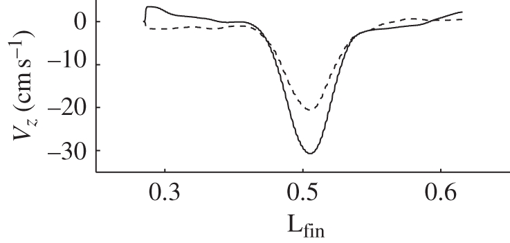
Average velocity of the downward jet generated by the robotic knifefish for fin frequencies of 3 and 4 Hz (dashed and solid line, respectively). The velocity of the jet was calculated from the DPIV data along a line approximately 7 cm below and parallel to the bottom edge of the ribbon fin, on the midsagittal plane.
On the transverse plane half way along the fin length, the downward jet is also evident, as is the tip vortex generated by the motion of the fin (figure 8). Figure 8a shows the velocity vectors on the transverse plane. The ribbon fin is located at the top of the images, and the colour map represents the z velocity. Figure 8b depicts the streamlines coloured by the magnitude of the velocity. From this panel, it is possible to observe the tip vortex that the ribbon fin generates as well as the downward jet.
Figure 8.
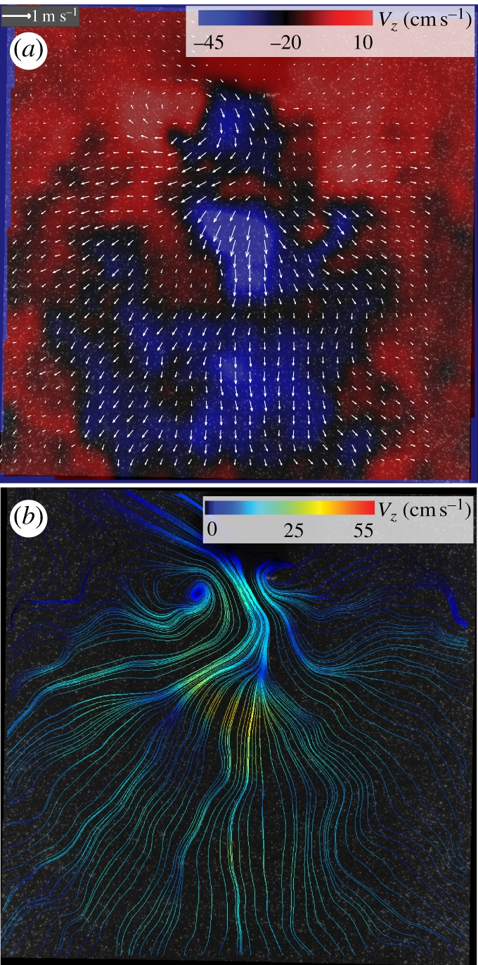
Flow structure on a transverse plane along the robotic knifefish, actuated with inward counter-propagating waves. (a) The velocity vector field (only every fourth vector is plotted). The colour map indicates the downward velocity, Vz. (b) Streamlines of the flow coloured by the magnitude of the velocity. The robot was operated at 4 Hz, θmax = 30° and there were two full wavelengths along the ribbon fin. The robotic fish is located at the top of the images, and the transverse plane is located at 0.5Lfin.
Figure 9a shows the heave force generated by robotic knifefish as a function of frequency using inward counter-propagating waves, outward counter-propagating waves, standing waves and unidirectional waves. In all cases, the heave force increases with frequency (except for one data point for standing waves). The inward propagating waves generate more heave force when compared with the outward and unidirectional waves for most of the frequencies studied. In figure 9b, the heave forces are shown along with the standard deviation. As can be observed, even though the average heave force from standing waves is very close to the heave force for inward propagating waves for f = 3–5 Hz, the standard deviation of the heave force from standing waves is much higher when compared with the other types of fin actuation. This could lead to large oscillations in movement.
Figure 9.

Upward force generated by the robotic knifefish as a function of frequency. (a) Force generated as a function of frequency for: inward counter propagating waves (blue), outward waves (red), unidirectional waves (black) and standing waves (green). (b) Force generated along with vertical bars to show the standard deviation. The inset shows the force versus time for inwards waves at f = 3 Hz. The grey horizontal line of the inset is the mean force. The ribbon fin was actuated with θmax = 35° and two full wavelengths along the fin.
4. Discussion
A. albifrons hovers by sending inward counter-propagating waves along its ventral ribbon fin. This mode of fin movement, in addition to facilitating station-keeping along the longitudinal axis, provides an upward force to the fish. This upward force prevents the fish from sinking, given that the fish is slightly more dense than the water, and is used to generate upward manoeuvers by the fish during normal locomotion.
Our previous work on ribbon fin propulsion and black ghost simulations shows that the ribbon fin generates a streamwise central jet with associated vortex rings [6,13]. In this case, the inward counter-propagating wave along the ribbon fin generates two opposite fluid jets that collide at an angle. After the jets collide, they are deflected downward (figures 5a–c and 6a). The forward and backward momentum which the ribbon fin imparts to the fluid along its length is cancelled. However, the downward momentum imparted to the fluid—owing to the deflection of the streamwise jet—creates an upward resultant force on the fish body. The resultant force is in the midsagittal plane, pushing the body straight upward, so long as the two counter-propagating waves are generating the same magnitude of fluid momentum (for example, if they are both sine waves with identical frequency, wavelength and amplitude). This downward jet is not present in the case of outward counter-propagating waves. For standing waves, the jet associated with the fin motion oscillates from downward to upward, and it is weaker when compared with the inward counter-waves.
The vortex structure associated with inward counter-propagating waves is complex (figure 5d,e). There are vortex structures associated with the streamwise central jet, and the tip vortex associated with the bottom edge of the fin, in addition to the vortex generated by the front and back edge of the fin. As can be observed in figure 5d and previously reported by Shirgaonkar et al. [6], the streamwise central jet generates vortex ring. For inward counter-propagating waves, these vortex structures are generated from the two oppositely travelling jets and they collide in the middle section of the fin length. Figure 10 depicts a simplified schematic of the flow behaviour and the main vortex rings associated with the propagation of inward counter-waves along the ribbon fin of A. albifrons. The resultant force is also shown.
Figure 10.

Schematic of flow field and primary vortex rings. The red arrows indicate the flow path, red and blue circles indicate the vortex rings, and FR indicates the resultant force on the fish due to the counter-propagating waves. The rotation of the vortex rings are indicated by their respective arrows.
In addition to the heave generated by the downward jet associated with inward counter-propagating waves, there is a heave force that results from the downward shedding of the tip vorticity attached to the fin [6] and from the angle at which the fin jet is generated. The angle of the fin jet and the tip vorticity attached to the fin can be observed in figure 6a,b and in figure 8, respectively. Even though these two factors contribute to the heave force generation, there is a significant increase (approx. 40%) in the heave force from inward counter-propagating waves when compared with outward-propagating waves because of the downward deflection of the streamwise jet. There is a 63 per cent increase in heave force from inward waves compared with unidirectional waves at low undulation frequencies. In the case of standing waves, low frequencies produce small or even negative heave force. For high frequencies, the mean heave force is very close to inward counter-propagating waves. However, the oscillation of the heave force for standing waves is substantially higher when compared with the other modes of fin actuation (figure 9b). Regardless of the type of fin actuation, the heave force has periodic variations in magnitude. For the case of unidirectional waves, the thrust and heave force variations are at twice the frequency of the travelling wave [6]. The reason for this is that the momentum imparted to the fluid for a given fin cross section has two maxima during one wave cycle. For inward counter-propagating waves, the heave force will have similar periodicity plus the effect of the interference of the counter-propagating waves (see inset on figure 9b).
The use of inward counter-propagating waves for hovering or vertical swimming provides mechanical benefits when compared with the other types of fin actuation. In addition to increasing the vertical force and reducing the force oscillations, a clear advantage of counter-propagating waves is that the fish can easily modulate the parameters of the two travelling waves to compensate for changes in the ambient flow. In addition, it can easily adjust its forward and backward movement and generate upward motion if needed.
The phenomenon of counter-propagating waves dovetails well with a unique sensory specialization of a subset of the ribbon-finned fishes, the weakly electric knifefish that are the focus of this study. These fish have a higher density of sensory receptors along the top edge of their body [14], which we have previously shown plays an important role in their prey-hunting behaviour [4,5]. For example, our prior research determined that the majority of the detected prey were directly above the body [5]. The fish quickly reaches these prey, potentially through the principle of heave force generation through counter-propagating waves.
The rich locomotor capability of ribbon fin-based propulsion is a remarkable testament to the need for a multi-directional propulsor in an animal with omnidirectional sensing abilities [4]. The phenomenon of counter-propagating waves also provides an approach for generating novel force directions on robotic undulators, an emerging new technology for propelling underwater vehicles [15–17].
Acknowledgements
We thank five anonymous reviewers for their helpful suggestions. This work was supported by NSF grant IOB-0517683 to M.A.M. and by an NSF CDI grant to M.A.M., N.A.P. and G.V.L. Partial support was provided by NSF CAREER CTS-0134546 to N.A.P. and CBET-0828749 to N.A.P. and M.A.M. O.M.C. acknowledges the support of a D.F.I fellowship. We also want to thank the SERPENT Project for the Regalecus glesne video.
References
- 1.Blake R. W. 1978. On balistiform locomotion. J. Marine Biol. Assoc. 58, 73–80 10.1017/S0025315400024401 (doi:10.1017/S0025315400024401) [DOI] [Google Scholar]
- 2.Blake R. W. 1983. Swimming in the electric eels and knifefishes. Can. J. Zool. 61, 1432–1441 10.1139/z83-192 (doi:10.1139/z83-192) [DOI] [Google Scholar]
- 3.Albert J. S., Crampton W. G. R. 2005. Diversity and phylogeny of neotropical electric fishes (Gymnotiformes). Electroreception, pp. 360–409 New York, NY: Springer [Google Scholar]
- 4.Snyder J. B., Nelson M. E., Burdick J. W., MacIver M. A. 2007. Omnidirectional sensory and motor volumes in an electric fish. PLoS Biol. 5, 2671–2683 10.1371/journal.pbio.0050301 (doi:10.1371/journal.pbio.0050301) [DOI] [PMC free article] [PubMed] [Google Scholar]
- 5.MacIver M. A., Sharabash N. M., Nelson M. E. 2001. Prey-capture behavior in gymnotid electric fish: motion analysis and effects of water conductivity. J. Exp. Biol. 204, 543–557 [DOI] [PubMed] [Google Scholar]
- 6.Shirgaonkar A. A., Curet O. M., Patankar N. A., MacIver M. A. 2008. The hydrodynamics of ribbon-fin propulsion during impulsive motion. J. Exp. Biol. 211, 3490–3503 10.1242/jeb.019224 (doi:10.1242/jeb.019224) [DOI] [PubMed] [Google Scholar]
- 7.Eschmeyer W. N., Herald E. S., Hammann H. 1983. A field guide to Pacific coast fishes of North America. Boston, MA: Houghton Mifflin Company [Google Scholar]
- 8.Bourton J. 2010. Giant bizarre deep sea fish filmed in gulf of mexico. BBC News, retrieved 26 August 2010. See http://neuromech.northwestern.edu/publications/oarfish_video.mov. [Google Scholar]
- 9.MacIver M. A., Nelson M. E. 2000. Body modeling and model-based tracking for neuroethology. J. Neurosci. Meth. 95, 133–143 10.1016/S0165-0270(99)00161-2 (doi:10.1016/S0165-0270(99)00161-2) [DOI] [PubMed] [Google Scholar]
- 10.Curet O. M., AlAli I. K., MacIver M. A., Patankar N. A. 2010. A versatile implicit iterative approach for fully resolved simulation of self-propulsion. Comp. Methods Appl. Mech. Eng. 199, 2417–2424 10.1016/j.cma.2010.03.026 (doi:10.1016/j.cma.2010.03.026) [DOI] [Google Scholar]
- 11.Lauder G. V., Madden P. G. A. 2006. Learning from fish: kinematics and experimental hydrodynamics for roboticists. Int. J. Automation Comp. 4, 325–335 10.1007/s11633-006-0325-0 (doi:10.1007/s11633-006-0325-0) [DOI] [Google Scholar]
- 12.Torres R. R., Curet O. M., Lauder G. V., MacIver M. A. 2010. The kinematics of ribbon fin propulsion in a weakly electric knifefish. [Google Scholar]
- 13.Shirgaonkar A. A., MacIver M. A., Patankar N. A. 2009. A new mathematical formulation and fast algorithm for fully resolved simulation of self-propulsion. J. Comput. Phys. 228, 2366–2390 10.1016/j.jcp.2008.12.006 (doi:10.1016/j.jcp.2008.12.006) [DOI] [Google Scholar]
- 14.Carr C. E., Maler L., Sas E. 1982. Peripheral organization and central projections of the electrosensory nerves in gymnotiform fish. J. Comp. Neurol. 211, 139–153 10.1002/cne.902110204 (doi:10.1002/cne.902110204) [DOI] [PubMed] [Google Scholar]
- 15.MacIver M. A., Fontaine E., Burdick J. W. 2004. Designing future underwater vehicles: principles and mechanisms of the weakly electric fish. IEEE J. Ocean. Eng. 29, 651–659 10.1109/JOE.2004.833210 (doi:10.1109/JOE.2004.833210) [DOI] [Google Scholar]
- 16.Epstein M., Colgate J. E., MacIver M. A. 2005. A biologically inspired robotic ribbon fin. In Proc. 2005 IEEE/RSJ Int. Conf. on Intelligent Robots and Systems, workshop on morphology, control, and passive dynamics, 1 August 2005, Edmonton, Alberta, Canada [Google Scholar]
- 17.Low K. H. 2007. Design, development and locomotion control of bio-fish robot with undulating anal fins. Int. J. Robot. Automation 22, 88–99 10.2316/Journal.206.2007.1.206-1009 (doi:10.2316/Journal.206.2007.1.206-1009) [DOI] [Google Scholar]