Abstract
The paper reports an important achievement in MRI instrumentation, a pneumatic, fully actuated robot located within the scanner alongside the patient and operating under remote control based on the images. Previous MRI robots commonly used piezoelectric actuation limiting their compatibility. Pneumatics is an ideal choice for MRI compatibility because it is decoupled from electromagnetism, but pneumatic actuators were hardly controllable. This achievement was possible due to a recent technology breakthrough, the invention of a new type of pneumatic motor, PneuStep (1), designed for the robot reported here with uncompromised MRI compatibility, high-precision, and medical safety. MrBot is one of the “MRI stealth” robots today (the second is described in this issue by Zangos et al.). Both of these systems are also multi-imager compatible, being able to operate with the imager of choice or cross-imaging modalities. For MRI compatibility the robot is exclusively constructed of nonmagnetic and dielectric materials such as plastics, ceramics, crystals, rubbers and is electricity free. Light-based encoding is used for feedback, so that all electric components are distally located outside the imager’s room. MRI robots are modern, digital medical instruments in line with advanced imaging equipment and methods. These allow for accessing patients within closed bore scanners and performing interventions under direct (in scanner) imaging feedback. MRI robots could allow e.g. to biopsy small lesions imaged with cutting edge cancer imaging methods, or precisely deploy localized therapy at cancer foci. Our robot is the first to show the feasibility of fully automated in-scanner interventions. It is customized for the prostate and operates transperineally for needle interventions. It can accommodate various needle drivers for different percutaneous procedures such as biopsy, thermal ablations, or brachytherapy. The first needle driver is customized for fully automated low-dose radiation seed brachytherapy. This paper gives an introduction to the challenges of MRI robot compatibility and presents the solutions adopted in making the MrBot. Its multi-imager compatibility and other preclinical tests are included. The robot shows the technical feasibility of MRI-guided prostate interventions, yet its clinical utility is still to be determined.
Keywords: MRI Robot, image-guided intervention (IGI), MRI compatible, multi-imager compatible, pneumatic motor
Introduction
A survey of robot publications in the medical literature reveals that the impact of medical robotics has exponentially grown since its inception in late 1980s. Robots do not only augment the physician’s manipulation capabilities, but also establish a digital platform for integrating medical information (2,3). Medical imaging data, in particular, gives robots abilities unattainable to humans, because, unlike humans, robots and imagers are digital devices. Image-guided interventions (IGI) expand radiology practice above and beyond traditional diagnosis (4), and do so with the use of modern tools.
IGI robotic systems, nevertheless, rely on the development of special imager interfaces, image registration, image-guided control algorithms, and also impose stringent requirements on the robotic hardware for imager compatibility, precision, sterility, safety, and nevertheless size and ergonomics. A robot’s compatibility with a medical imager refers to the capability of the robot to safely operate within the confined space of the imager while performing its clinical function, without interfering with the functionality of the imager. This depends indeed on the type of intervention and imager used. In a previous report (5), we have collected a set of imager compatibility prescriptions from scientific papers and imager technical notes and assembled a global definition of concurrent compatibility with multiple types of imagers, multi-imager compatibility. The study also derives a compatibility measure for individual imagers and, as expected, found the compatibility with Magnetic Resonance Imagers (MRI) to be most demanding.
On the other hand, the potential of MRI-guided interventions is significant for the reason that MRI is the method of choice for imaging soft tissue, and, with spectroscopy and special markers, is the most promising imaging modality for tumor detection (6,7).
The design and construction of MRI compatible robots is a very challenging engineering task because most of the components commonly used in robotics may not be used in close proximity of the imager. MRI scanners use magnetic fields of very high density (up to several Tesla), with pulsed magnetic and radio frequency fields. Within the imager, ferromagnetic materials are exposed to very high magnetic interaction forces and heating may occur in conductive materials by electromagnetic induction. The use of electricity may cause interference leading to image artifacts and/or robot signal distortions. As such, ideal materials are nonmagnetic and dielectric.
The problem becomes even more intricate for robot actuation, where the ubiquitous electromagnetic motors are incompatible with MRI by their principle of operation. MRI robotic research to date has commonly utilized piezoelectric (ultrasonic) motors (8–11). These are magnetism free but employ high-frequency currents creating image distortion if operated closer than 0.5m from the image isocenter (10) and necessitating deactivation during imaging.
Pneumatic actuation is a fundamentally flawless option for MRI compatibility. The major limitation of the pneumatic actuators, however, has been their reduced precision in controlled motion (12). The robot presented here utilizes a new type of pneumatic motor, PneuStep (5), specifically developed for this application. This is fully MRI compatible and uses a step motor principle to achieve precision of motion in a safe and easily controllable manner.
Previous research on MRI compatible robots has been quantitatively limited, yet a company has already introduced a commercial MR-IGI robot.
The earliest work was perhaps performed at the Brigham and Women’s Hospital (BWH) (Boston MA, USA) in collaboration with AIST-MITI, Japan (13). A robotic surgical assistant was constructed for open MRI presenting five piezoelectrically actuated degrees of freedom (DOF). The manipulator is located at the top of the imager between the vertical coils of the MRI, and presents two long arms that extend to the imaging region to provide a guide for manual instrument manipulation (9). Work continued with the development of a one-arm needle support (14) and improved accuracy results were reported (15).
An MRI compatible needle insertion manipulator was built at the Medical Precision Engineering lab of the University of Tokyo (8). The system was designed for neurosurgery applications and tested in-vitro. The same group has also designed a neurosurgical micro forceps manipulator (16).
A research group from the University of Calgary, Canada has reported their ongoing work and prototype specifications for the development of an MRI neurosurgical assistant with bilateral arms (11).
The most evolved work in the field started at the Institute for Medical Engineering and Biophysics (IMB), Karlsruhe, Germany, and has a long history for this new research topic. Several versions of a robotic system for breast lesion biopsy and therapy under MR guidance were developed (17,18). Then, a system for general IGI under either computer tomography (CT) or MRI guidance was developed. Earlier systems used piezo actuation but a hybrid piezo-pneumatic system was also reported (10). They also give a well reasoned discussion on the advantages offered by pneumatic actuation in MRI environments. This research led to the creation of a spin-off company, Innomedic (Herxheim, Germany, http://innomedic.com/) to introduce the first commercial MR-IGI system, Innomotion. The system includes a 5 DOF robot to position a needle guide for manual needle insertion (see the article from Zangos et al. in the present issue of MITAT), and has very elegant and compact way of fitting within the MRI bore based on an outstanding kinematic design. Moreover, the current version uses all pneumatic actuation and fiber optic sensing. Because the pneumatics is done with cylinders (special, non-metallic, high static and dynamic friction) a sophisticated control algorithm had to be used to servo-control the pneumatics through long hoses.
Pneumatics gives outstanding MRI compatibility. It has only been used in two systems, the Innomotion abdominal access robot and the reported MrBot prostate robot. Compared to Innomotion, our system is fully actuated and uses special MRI more precise and controllable motors. The full actuation of the robot is important for remote operation, so that interventions can be performed within the scanner. With manual needle insertion repeated in-and-out of the scanner moves are needed between accessing the patient and imaging.
On the clinical application side, our robot is specifically customized for needle access of the prostate gland under MRI guidance. Such manual procedures have been experimentally performed in a very few clinical trials, due to the complexity of the MR-IGI, inconvenient access related to the scanner, and the lack of proper instrumentation. Menard (19) at the NIH Bethesda, MD, USA, investigated the feasibility of IGI for high dose prostate brachytherapy in a closed bore MRI scanner using a needle guide registered to the MRI. D’Amico and Tempany at BWH performed clinical trials for transperineal biopsy and seed brachytherapy on an open MRI scanner (20). Recently, a passive needle guide packaged within a custom MR coil was tested on animal models (21) and in clinical trials at the NIH for transrectal prostate biopsy.
The work presented here is significantly different from previous MRI compatible robots. Other researchers concentrated on selecting materials, motors, and sensors that may reasonably work with the MRI. In our case, we made new actuators especially for this application.
Clinical application and robot specifications
The MrBot robot is designed for image-guided percutaneous needle interventions of the prostate. The prostate is a gland located directly beneath the bladder and completely surrounding the proximal part of the urethra. The gland is walnut-shaped and measures about 40×30×30 mm. Depending on the amount of subcutaneous tissue, in most men the center of the prostate lies about 70±20 mm beneath the perineal skin.
The space in closed bore MRI scanners along the patient is very limited, because the size of the bore is on the order of 500 mm in diameter. Previous clinical trials (19) revealed that perineal access legroom may be gained if the patient is positioned in the MRI head first in the left lateral decubitus position (on his side). As such, MrBot is designed to operate as represented in Figure 1 (Movie 1), where the patient (1) and robot (4) are placed within the bore of an MRI scanner (2).
Figure 1.
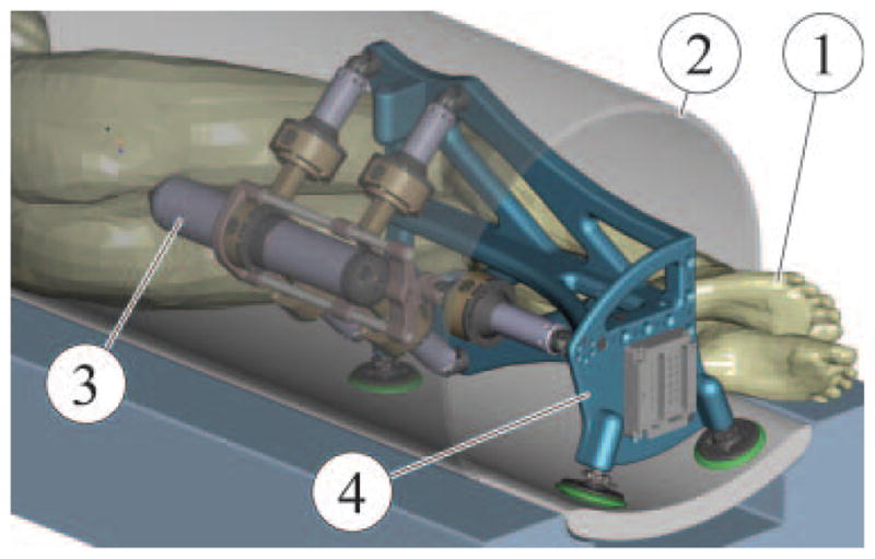
CAD Rendering of an MRI intervention setup
Two approaches are used for prostate needle access: transrectal and transperineal each with its pros and cons. Traditionally, prostate biopsies are done transrectally under ultrasound guidance, and the transperineal access is used for brachytherapy and thermal ablations also with the ultrasound (22). The main advantage of the transrectal approach is the reduced anesthetic requirement. The robot was designed for transperineal access because this allows for a wider range of clinical interventions to be performed with the same robot, by simply changing the needle driver. A modular structure comprising a robotic component (4) that can be utilized with intervention specific needle drivers (3) was sought for different applications such as biopsy, brachytherapy, thermal ablations, or therapeutic injections.
The range of motion is similar to the size of the template commonly used in brachytherapy (50×50 mm) and a slight angulation of the needle (±10°) is desired. For safety, fail-safe non-back-drivable actuation is required along with slow speeds (<20 mm/s). High velocity needle insertion was allowed to facilitate piercing.
Robot kinematics
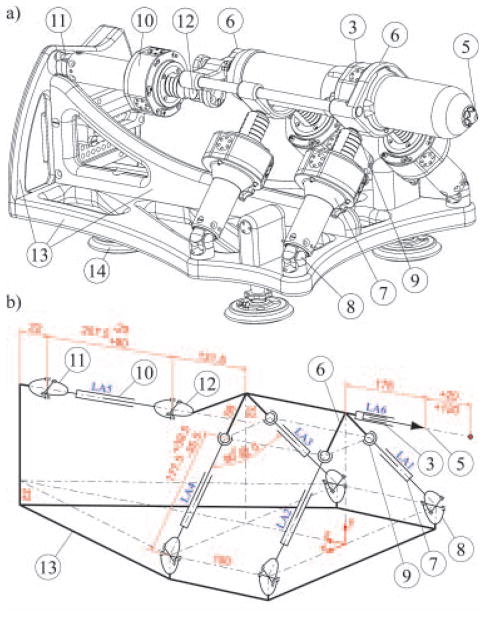
The MrBot robot was constructed in the form of a platform supported by articulated linear actuators in a 5 DOF parallel link structure, as presented in Figure 2.
Figure 2.
(a) Isometric representation and (b) kinematic diagram (mm dimensioning units).
The needle driver (3) housing the needle (5) attaches coaxially to the platform (6). Two universal (U) joints (11,12) connect the back actuator LA5 (10) to the base (13) and platform (6) respectively. Their role is to prevent the rotation of the platform about the axis of the needle (like a CV axel). The other four actuators LA1-4 (7) present U-joint connections (8) to the base to prevent their spin and spherical joints (9) at the platform side.
The needle driver is IGI specific involving several other DOF. The needle is actuated by a pneumatic piston whose cylinder is precisely positioned with a linear actuator LA6. As such, the depth of insertion is always at the end-of-stroke, but this limit is shifted with the entire cylinder before the insertion (23). This allows for quick (pressure regulated) needle insertion at a precisely specified depth. Additional DOF are also required for special needle drivers (e.g. seed loading). These may only require binary(end-to-end) actuation and may be implemented with traditional pneumatic cylinders.
As such, the overall system presents six position-controlled DOF, with two redundant translations in the direction of the needle. The rotation about the axis of the needle is blocked. The redundant motions are used for the initial positioning of the needle driver and subsequently for needle insertion. Three translations (X, Y, Z) and two rotations (X, Y) are available for controlled positioning of the needle driver, as shown in (Movie 2).
The parallel link structure was elected for its known stiffness. The architecture and sizing (Figure 2b) was selected iteratively with kinematic analyses and IGI simulation performed with Pro/Engineer (PTC, Needham, MA, USA) CAD/M software (as in Figure 1).
As for most parallel robots, the inverse kinematics of the robot is trivial and has an analytic form and the direct kinematics is numerically evaluated.
Robot design
For multi-imager compatibility, all components are constructed of nonmagnetic and dielectric materials such as Polyetherimide (Ultem 1000), Delrin, Nylon 6/6, Peek 1000, Garolite G-11, Polyimide, high-alumina ceramic, glass, sapphire, PTFE (Teflon), Silicone rubber. These materials have been successfully tested for MR and actually multi-imager compatibility (5).
Pneumatic actuation was considered optimal because it is decoupled from electro-magnetism. The hydraulics is also decoupled, but was dismissed for its risk of leakage that would compromise sterility. Fine position servo-pneumatic control with long connection hoses is challenging and was dismissed for reliability concerns. A highly geared pneumatic actuation could potentially work but was dismissed because fail-safe implementation would require breaks and complicate the design. Since no actuator could satisfy the requirements we opted to make one for the application.
The new motor, PneuStep is the first pneumatic step motor (1). This allows for easily controllable motion with fail-safe operation (Figure 3).
Figure 3.
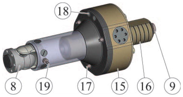
Linear actuator using the rotary PneuStep motor.
The PneuStep (15) presents three pneumatic ports (17). Step motion is achieved by sequentially pressurizing the ports (pneumatic commutation). The motor includes an integrated gearhead and a custom fiber optic quadrature encoder (ports 18) for closed-loop control or redundant sensing in open-loop step operation. The output of the motor (which presents a central bore) includes a central nut engaging a screw (16) for linear actuation. In the configuration implemented with closed-loop control, the linear size of the motor step is 55 μm and the maximum speed is 16.6 mm/s. The linear actuator presents fail-safe operation because in case of malfunction it may only lock, and is non-back-drivable.
A fiber optic limit switch is set at one end of the linear travel (19) for providing the zero reference for linear motion.
Most of the hardware had to be custom-made. The Geometric Element Modeling (GEM, similar to FEA) package of Pro/Engineer was involved for structural analyses.
Depending on the clinical intervention and the type of imager used, the robot may be mounted either on its side (Figure 1) or horizontally (Figure 2). In either case, the robot frame (13) attaches to the table of the imager with three suction cups (14), mounted to either side.
The control unit
The robot is controlled from a unit located outside the imager’s room including all MRI incompatible components of the system. As shown in Figure 4, the robot (4) is connected to the control cabinet (20) by a bundle of hoses (21). The 6m hoses were sufficiently long for our MRI room setup and this is consistent with other reports (10).
Figure 4.
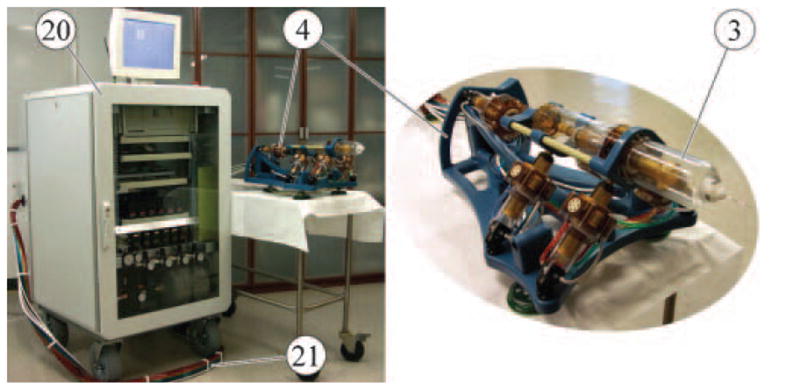
Robot and control unit connected with 6m long hoses.
A dual-processor industrial PC equipped with a motion control card (MC-8000, 8-axis PCI-DSP by PMDI, Victoria, BC, Canada) is used. An electro-pneumatic interface is implemented with direct-acting solenoid valves (NVKF334V-5D by SMC Corp., Indianapolis, IN, USA). A special driver was designed to control the valves from the motion control card (1). An electronic air regulator (24) is used for the supply. The electro-optical interface is implemented with D10 Expert fiber optic sensors (Banner Engineering Corp., Minneapolis, MN, USA). Three of these sensors are used for each motor, two for measuring incremental rotary motion with quadrature encoding, and one as a linear motion limit-switch.
Preclinical tests
The positioning errors of the robot itself are the first component of the errors in image-guided systems. These have been measured by mounting the robot on the table of a CNC vertical machining center and using a coordinate measurement probe to take the measurements. The resolution of the machine (HAAS VF-1) is 1 μm and the repetability of the probe (Renishaw, MP-10) is also 1 μm. A zero reference was set at the center of a 40×40×40 mm work volume (prostate size) and the robot was successively commanded to move 10 mm at a time in all directions acquiring 125 samples. Position measurements were taken with the robot at rest. The absolute positioning errors of the robot are presented in Table I. The coordinates are aligned in the directions of the system in Figure 2 and the norm is the Euclidian norm of the component errors. The robot was then commanded to repeatedly move to the same locations and 317 samples were taken throughout the volume. The difference between the measurements taken at the same location was used to calculate the repetability.
Table I.
Robot errors and repetability.
| [mm] units | X | Y | Z | Norm | |
|---|---|---|---|---|---|
| Positioning Errors 125 Samples | Average | −0.145 | 0.003 | −0.017 | 0.315 |
| Standard Deviation | 0.188 | 0.182 | 0.175 | 0.143 | |
| Repetability 317 Samples | Average | 0.013 | −0.018 | 0.019 | 0.076 |
| Standard Deviation | 0.065 | 0.038 | 0.037 | 0.047 |
The experiments show that in average the robot achieves the desired position within 0.315 mm and this could potentially be improved with kinematic identification (especially in the X direction).
A similar test was conducted for repetability with an optical tracking system and an active marker (Polaris, NDI, Ontario, Canada). The results were surprisingly similar given the much lower measurement capabilities of the optical tracker (0.32 mm, but in very unfavorable conditions, throughout the measurement volume with one marker) compared to the coordinate measurement machine. Optical tracking was then used to take measurements of the robot inside a 1.5T MRI scanner. These showed a mean norm repetability of 0.060 mm with 0.032 mm standard deviation. We tend to believe that these measurements are valid because the tracker took correct measurements outside the scanner (careful measurements, repeated and in proper range). Unfortunately, we could not take better measurements in the MRI and testing the tracker was not the object of this study. If valid, these data show that the magnetic field does not influence the precision of motion. Image-guided tests (which include additional errors) and image-based measurements (which are also of relatively low precision) showed mean errors of 0.72±0.36 mm (23).
Imager compatibility tests (Figure 5) were performed with the robot in X-Ray, CT, Closed MRI (1.5T), Open MRI (0.5T), and Ultrasound (in rows). For each experiment a photograph of the setup, a graph, and an image of the respective dataset (in columns) are presented.
Figure 5.
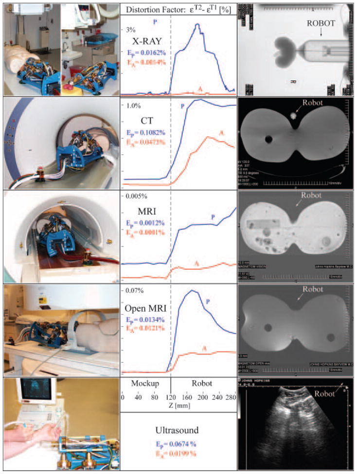
Multi-imager compatibility tests.
A human torso mockup, a kidney model, and an arm were used in the experiments. Tests were performed according to a previously reported multi-imager compatibility method (5), in which difference imaging (εT2−εT1) is involved to show the level of image distortion due to the presence of the robot in the imager field (P-passive), as well as its activation (A-active). The (P) graphs plot a mean measure of the pixel value differences between images taken with (εT2) and without (εT1) the robot versus a coordinate measuring the distance between the mockup and the robot. The (A) test is similar, but the differences are taken between images with and without robot motion. The low levels of imaging errors in the left side of the graphs (Mockup side) show that the presence and activation of the robot during imaging does not affect image quality in the region of interest (where the IGI site is). The right sides of the graphs (Robot side) show whether the robot is visible or not in the medical image. These graphs and the medical images in the right column show that the robot is visible in X-Ray based imagers, but is translucent under MRI and ultrasound. EP and EA percent coefficients give an integral measure of the graphs in the mockup region. These very low coefficients show that the robot does not create image artifacts even if operated during imaging in any class of imaging equipment. Coefficients EP<1% and EA<0.5% were associated by experienced radiologists with minimal or unperceivable artifacts (5).
The MrBot robot was then filled alongside a man within a standard bore 1.5 Tesla MRI scanner, as shown in Figure 6.
Figure 6.
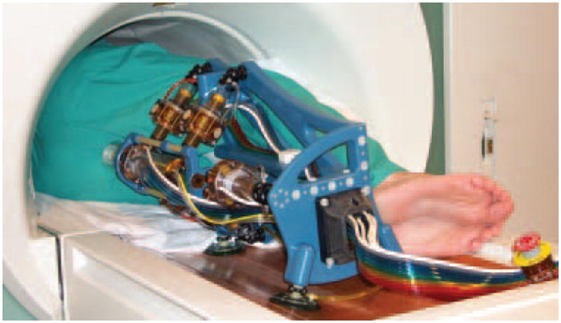
MrBot in a 3T MRI scanner.
With the needle injection stages deactivated, motion tests performed showed that the robot presents sufficient clearance to move as designed, performing translational as well as pivoting moves about the needle driver’s nozzle (Movie 3).
Other preclinical tests were performed under image guidance. The registration methods used, the accuracy of registration, and a fully automated seed brachytherapy needle driver are presented in reference (24). Image guided seed deployment experiments are presented in (23). Other preclinical tests in cadaver models and animal experiments and are in progress and have yielded promising partial results.
Conclusion
The paper presents a new robot for MRI guided needle access of the prostate gland. Preclinical tests are promising, but the clinical utility of the system is yet to be established. The paper does not elaborate on needle driver designs. Only one driver has been made thus far, for brachytherapy. Additional drivers are planned for biopsy and thermal ablations. The kinematic structure of the robot and its architecture limit the application range of the robot to transperineal needle insertions. However, this work shows the feasibility of remote, in-scanner interventions and MRI stealth new image-guided instruments. The PneuStep motor developed for the reported robot is a breakthrough technology in MRI compatibility. The PneuStep will enable other applications from our group and hopefully other researchers in the field.
Supplementary Material
1. Movie 1: MrBot Robot, CAD Animation of the Interventional Setup [wmv, 495Kb]: http://urology.jhu.edu/urobotics/pub/2007-stoianovici-mitat-M1.wmv.
2. Movie 2: MrBot Robot Motion [wmv, 1.58Mb]: http://urology.jhu.edu/urobotics/pub/2007-stoianovici-mitat-M2.wmv.
3. Movie 3: MrBot Robot in the MRI Scanner [wmv, 1.41Mb]: http://urology.jhu.edu/urobotics/pub/2007-stoianovici-mitat-m3.wmv.
Acknowledgments
This work was supported by the National Cancer Institute (NCI) of the National Institutes of Health (NIH) under Grant CA88232, the Prostate Cancer Foundation (PCF), and the Patrick C. Walsh Prostate Cancer Foundation (PCW). The contents are solely the responsibility of the authors and do not necessarily represent the official views of NIH-NCI, PCF, or the PCW.
References
- 1.Stoianovici D, Patriciu A, Mazilu D, Petrisor D, et al. A New Type of Motor: Pneumatic Step Motor. IEEE/ASME Transactions on Mechatronics. 2007;12:98–106. doi: 10.1109/TMECH.2006.886258. http://urology.jhu.edu/urobotics/pub/2007-stoianovici-tmech.pdf. [DOI] [PMC free article] [PubMed]
- 2.Taylor RH, Stoianovici D. Medical robotics in computer-integrated surgery. IEEE Transactions on Robotics and Automation. 2003;19:765–81. http://urology.jhu.edu/urobo-tics/pub/2003-taylor-ieeetra.pdf.
- 3.Satava RM. The operating room of the future: observations and commentary. Semin Laparosc Surg. 2003;10:99–105. doi: 10.1177/107155170301000302. [DOI] [PubMed] [Google Scholar]
- 4.Jolesz FA. Neurosurgical suite of the future. II. Neuroimaging Clin N Am. 2001;11:581–92. [PubMed] [Google Scholar]
- 5.Stoianovici D. Multi-Imager Compatible Actuation Principles in Surgical Robotics. International Journal of Medical Robotics and Computer Assisted Surgery. 2005;1:86–100. doi: 10.1002/rcs.19. http://urology.jhu.edu/urobotics/pub/2005-stoianovici-MRCASJ.pdf. [DOI] [PMC free article] [PubMed]
- 6.Hricak H. MR imaging and MR spectroscopic imaging in the pre-treatment evaluation of prostate cancer. Br J Radiol. 2005;78(Spec No 2):S103–11. doi: 10.1259/bjr/11253478. [DOI] [PubMed] [Google Scholar]
- 7.Kurhanewicz J, Swanson MG, Nelson SJ, Vigneron DB. Combined magnetic resonance imaging and spectroscopic imaging approach to molecular imaging of prostate cancer. J Magn Reson Imaging. 2002;16:451–63. doi: 10.1002/jmri.10172. [DOI] [PMC free article] [PubMed] [Google Scholar]
- 8.Masamune K, Kobayashi E, Masutani Y, Suzuki M, et al. Development of an MRI-compatible needle insertion manipulator for stereotactic neurosurgery. J Image Guid Surg. 1995;1:242–8. doi: 10.1002/(SICI)1522-712X(1995)1:4<242::AID-IGS7>3.0.CO;2-A. [DOI] [PubMed] [Google Scholar]
- 9.Chinzei K, Miller K. Towards MRI guided surgical manipulator. Med Sci Monit. 2001;7:153–63. [PubMed] [Google Scholar]
- 10.Hempel E, Fischer H, Gumb L, Hohn T, et al. An MRI-compatible surgical robot for precise radiological interventions. Computer Aided Surgery. 2003;8:180–91. doi: 10.3109/10929080309146052. [DOI] [PubMed] [Google Scholar]
- 11.Louw DF, Fielding T, McBeth PB, Gregoris D, et al. Surgical robotics: a review and neurosurgical prototype development. Neurosurgery. 2004;54:525–36. doi: 10.1227/01.neu.0000108638.05274.e9. [DOI] [PubMed] [Google Scholar]
- 12.Choi HS, Han CS, Lee KY, Lee SH. Development of hybrid robot for construction works with pneumatic actuator. Automation in Construction. 2005;14:452–9. [Google Scholar]
- 13.Chinzei K, Hata N, Jolesz FA, Kikinis R. MR compatible surgical assist robot: System integration and preliminary feasibility study. Medical Image Computing and Computer-Assisted Intervention - Miccai. 2000;1935:921–30. [Google Scholar]
- 14.Koseki Y, Koyachi N, Arai T, Chinzei K. Remote actuation mechanism for MR-compatible manipulator using leverage and parallelogram - workspace analysis, workspace control, and stiffness evaluation. Robotics and Automation. 2003;1:652–7. [Google Scholar]
- 15.Koseki Y, Kikinis R, Jolesz FA, Chinzei K. Precise evaluation of positioning repeatability of MR-compatible manipulator inside MRI. Medical Image Computing and Computer-Assisted Intervention - Miccai 2004, Pt 2, Proceedings. 2004;3217:192–9. [Google Scholar]
- 16.Miyata N, Kobayashi E, Kim D, Masamune K, et al. Micro-grasping forceps manipulator for MR-guided neurosurgery. Medical Image Computing and Computer-Assisted Intervention-Miccai 2002. 2002;2488(Pt 1):107–13. [Google Scholar]
- 17.Kaiser WA, Fischer H, Vagner J, Selig M. Robotic system for biopsy and therapy of breast lesions in a high-field whole-body magnetic resonance tomography unit. Invest Radiol. 2000;35:513–9. doi: 10.1097/00004424-200008000-00008. [DOI] [PubMed] [Google Scholar]
- 18.Felden A, Vagner J, Hinz A, Fischer H, et al. ROBITOM-robot for biopsy and therapy of the mamma. Biomed Tech (Berl) 2002;47(Suppl 1 Pt):12–5. doi: 10.1515/bmte.2002.47.s1a.2. [DOI] [PubMed] [Google Scholar]
- 19.Menard C, Susil RC, Choyke P, Gustafson GS, et al. MRI-guided HDR prostate brachytherapy in standard 1.5T scanner. Int J Radiat Oncol Biol Phys. 2004;59:1414–23. doi: 10.1016/j.ijrobp.2004.01.016. [DOI] [PMC free article] [PubMed] [Google Scholar]
- 20.Hata N, Jinzaki M, Kacher D, Cormak R, et al. MR imaging-guided prostate biopsy with surgical navigation software: device validation and feasibility. Radiology. 2001;220:263–8. doi: 10.1148/radiology.220.1.r01jl44263. [DOI] [PubMed] [Google Scholar]
- 21.Susil RC, Krieger A, Derbyshire JA, Tanacs A, et al. System for MR image-guided prostate interventions: canine study. Radiology. 2003;228:886–94. doi: 10.1148/radiol.2283020911. [DOI] [PMC free article] [PubMed] [Google Scholar]
- 22.Ragde H, Grado GL, Nadir B, Elgamal AA. Modern prostate brachytherapy. CA Cancer J Clin. 2000;50:380–93. doi: 10.3322/canjclin.50.6.380. [DOI] [PubMed] [Google Scholar]
- 23.Muntener M, Patriciu A, Petrisor D, Mazilu D, et al. Magnetic Resonance Imaging Compatible Robotic System for Fully Automated Brachytherapy Seed Placement. Urology. 2006;68:1313–7. doi: 10.1016/j.urology.2006.08.1089. http://urology.jhu.edu/urobotics/pub/2006-muntener-urology.pdf. [DOI] [PMC free article] [PubMed]
- 24.Patriciu A, Petrisor D, Muntener M, Mazilu D, et al. Automatic Brachytherapy Seed Placement under MRI Guidance. IEEE Transactions on Biomedical Engineering. 2007 Aug; doi: 10.1109/TBME.2007.900816. in press. [DOI] [PMC free article] [PubMed] [Google Scholar]
Associated Data
This section collects any data citations, data availability statements, or supplementary materials included in this article.
Supplementary Materials
1. Movie 1: MrBot Robot, CAD Animation of the Interventional Setup [wmv, 495Kb]: http://urology.jhu.edu/urobotics/pub/2007-stoianovici-mitat-M1.wmv.
2. Movie 2: MrBot Robot Motion [wmv, 1.58Mb]: http://urology.jhu.edu/urobotics/pub/2007-stoianovici-mitat-M2.wmv.
3. Movie 3: MrBot Robot in the MRI Scanner [wmv, 1.41Mb]: http://urology.jhu.edu/urobotics/pub/2007-stoianovici-mitat-m3.wmv.


