

Abstract
We have designed and constructed a machine that synthesizes two standard 96-well plates of oligonucleotides in a single run using standard phosphoramidite chemistry. The machine is capable of making a combination of standard, degenerate, or modified oligos in a single plate. The run time is typically 17 hr for two plates of 20-mers and a reaction scale of 40 nm. The reaction vessel is a standard polypropylene 96-well plate with a hole drilled in the bottom of each well. The two plates are placed in separate vacuum chucks and mounted on an xy table. Each well in turn is positioned under the appropriate reagent injection line and the reagent is injected by switching a dedicated valve. All aspects of machine operation are controlled by a Macintosh computer, which also guides the user through the startup and shutdown procedures, provides a continuous update on the status of the run, and facilitates a number of service procedures that need to be carried out periodically. Over 25,000 oligos have been synthesized for use in dye terminator sequencing reactions, polymerase chain reactions (PCRs), hybridization, and RT–PCR. Oligos up to 100 bases in length have been made with a coupling efficiency in excess of 99%. These machines, working in conjunction with our oligo prediction code are particularly well suited to application in automated high throughput genomic sequencing.
Probably the most common sequencing strategy being used in the Human Genome Project is a combination of random and directed sequencing. In the random shotgun phase (Selleri et al. 1995) a series of subclone ends are generated from a sequence template, typically resulting in reads of 300–700 bp. Alignment of these end sequences allows the assembly of these subclones into a number of contigs spanning most of the original template. Nevertheless, there will be certain regions where either there are gaps in the coverage or the quality, or reliability of the data is low. It is then necessary to utilize a directed strategy to close these gaps and improve the quality of the final assembly (Kupfer et al. 1995). The principal limitations on using a high throughput directed strategy has been the cost of the primers and a rapid turnaround time for the synthesis. Cost of primers is also a limiting factor in the level of accuracy achievable at a realistic cost. These concerns underline the need to generate large numbers of primers at a low cost. Current commercial costs are typically in the range of $0.65 to $1.00/base.
There are currently two high throughput systems available. The first, designed and built by the Human Genome Center at Lawrence Livermore National Lab (Sindelar and Jaklevic 1995) uses a multichannel format. The system also uses phosphoramidite chemistry, but in its current form is limited to 12 oligonucleotides each run. AMOS, the oligo synthesizer designed and built at the Genome Center at Stanford University (Lashkari et al. 1995) uses the same chemistry and synthesizes directly into a 96-well format on a reaction scale similar to our machine but is not available for license or replication. We therefore designed and constructed in-house our own oligo synthesizer, which is capable of producing two 96-well plates of oligos in a single run, and depending on the mode of operation of the machine, corresponds to a cost of ∼$0.09–$0.13/base ($0.06–$0.09 for reagents, $0.03 for operator wages). The system is simple to load and run and requires no user intervention once started. Currently we have three machines in use at UTSW, offering us the capability of producing 600 oligos/day, with additional units in construction to further increase our throughput.
METHODS
System Overview
The synthesizer has a footprint of ∼3 × 3 feet and stands ∼6 ft high. A photograph of the system is shown in Figure 1. The synthesis reagents are stored at the top of the machine in standard pressurized media bottles and are transferred by Teflon lines to the synthesis chamber located at the center portion of the machine. The electronics and computer controlling the machine are located in a separate cart that may be placed either inside or outside the main frame as convenience dictates. Two argon tanks (to provide bottle pressure and an inert synthesis environment) are strapped to the side of the frame. The machine is operated by a Macintosh Quadra 950 running a control program written in LabView (National Instruments, Austin, TX). The program guides the operator through the startup and shutdown procedures and controls the synthesis process while providing the user with a continuously updated system status.
Figure 1.
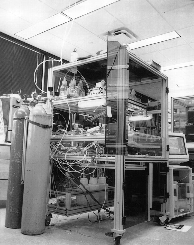
MerMade: Oligosynthesis (192/day); two machines in operation; >18,000 made to date.
Synthesis Chamber
There are three main components comprising the synthesis chamber: the inner chamber, the outer chamber, and the xy table (Fig. 2A,B). The two 96-well plates are placed inside two separate vacuum chucks (Fig. 3), which are then placed into the inner chamber, the inner chamber is sealed and mounted on the xy table. This in turn is contained within a larger outer chamber of sufficient size to accommodate the full motion of the table. The injection head is mounted on the top of the outer chamber, and the xy table, which is under the control of the computer, moves the plates around underneath the injection head. The chemistry is particularly sensitive to the presence of water vapour and air (Gait 1984), and the combination of the two chambers effectively excludes these contaminants from the reactions. In addition, argon is pumped continuously into the inner chamber, and a small gap between the top of the walls of the inner chamber and the roof of the outer chamber guarantees a constant flow of argon to minimize any contamination of the phosphoramidite and tetrazole lines by vapors from the deblocking and oxidizing lines.
Figure 2.

(A) Synthesis chamber schematic; (B) injection head schematic. Inside the reaction chamber are placed 96-well plates, mounted in vacuum chucks. The plates are moved around underneath the injection lines to allow introduction of each reagent into the wells at appropriate times in the synthesis cycle. Reagents are drained from the plates through the drain line (see also Fig. 3).
Figure 3.

Vacuum chuck and reaction plate. The plate is placed between the upper and lower parts of the vacuum chuck and bolted together. A gasket in the lower half of the chuck mates with the bottom of the plate to ensure a good seal. Reagents are injected in the top of the wells and drained out the bottom via a small hole when a vacuum is applied to the drain line. Surface tension prevents the reagents from draining before the vacuum is turned on.
Reagents
The reagents are provided by Cruachem (Dulles, VA), Beckmann Instruments (Fullerton, CA), ABI (Foster City, CA), and Glen Research (Sterling, VA) The phosphoramidites are delivered in powdered form in 15-gram quantities and are diluted with anhydrous acetonitrile (0.0002% H2O) directly into 500-ml reagent bottles in a separate glove box filled with argon. This provides sufficient quantities of reagents for 10 two-plate runs of 20-mers. The remaining reagents are also stored in 500-ml bottles with the exception of acetonitrile (VWR, Dallas, TX)—used for washing after each stage—which is contained in a 10-liter bottle.
Inner Chamber and Plate Chuck
The two plates are individually mounted inside two vacuum chucks to allow drainage of the reagent chemicals after each stage. The chuck consists of two parts that bolt together around the plate (Fig. 3). The lower half of the chuck contains a gasket to provide a seal between the plate and the chuck, and a drain line that is connected to a vacuum. The plates are mounted in the chucks before loading through a sealable access door in the top of the outer chamber.
Injection Head and Valves
The reagents are introduced into the wells via the injection head (Fig. 2A). This is located in the center of the access door (which also facilitates cleaning the head before each run). The injection head consists of 15 lead-throughs to carry the reagents inside the chamber. Six of the injection heads are in pairs. Four of these pairs are for the simultaneous injection of a phosphoramidite plus activator to minimize table movement for this stage. The fifth is for injection of the two chemicals for the capping stage. The final injection pair is for either modified or degenerate bases. The reagents are delivered from the bottles to the dc solenoid valves and from the valves to the lead-throughs by  -in.-diam. Teflon tubing. Silcone sealant is used to produce a seal through which the tubing enters the lead-through. The vacuum and argon delivery systems are controlled by eight AC solenoid valves. All of these valves are controlled individually by solid-state relays that are switched by the software. The smallest injection volumes obtainable with these valves is <20 μl. Realistically, to ensure proper mixing of the reagents in the wells, the injection volume should be at least 60 μl.
Electronics
The electronics has three principal components: the motor amplifier box, the relay box, and the power supply box. The xy table motors are controlled by a NuLogic0L controller card (NuLogic, Needham, MA) which sends the controlling signals from the software to the motor amplifier box. The motor amplifier box in turn sends the necessary voltages to the motors and returns motion limit and home signals back through the card to the control software. The valves are controlled by a National Instruments NB-DIO-96 card. Signals are sent from the card to three banks of relay cards (each card contains eight relays). Two cards control the DC valves for reagent injection; the third card controls the AC valves which are used for argon and vacuum systems. The AC and DC voltage sources for the motors and valves are provided by the voltage supply box.
Software
The synthesizer is controlled by a Macintosh Quadra 950 computer running LabView 3.1.1 (National Instruments, Austin, TX). The software was written in-house and controls all aspects of the machine operation. The startup procedure is performed by following a series of dialog boxes that prompt the operator through the necessary steps. Once the machine has been set up for a run and the synthesis procedure has been started no further user intervention is required. The software handles all of the table motion and valve operations, provides a continuous update on the status of the synthesis process (Fig. 4), and performs the required shutdown steps once the synthesis is complete. In addition, there are a series of options to allow the user to perform a variety of service and maintenance procedures (such as calibration of injection volumes and resetting plate offsets and well positions). It is also possible to shut down any well during a run should the drain hole become blocked.
Figure 4.

Run status screen.
All of the parameters necessary for the run are stored in a group of simple text files that are accessed by the control software. These files contain the sequence for each oligo as well as information about the injection volumes, the wait times for each stage in the synthesis cycle, the number of wash cycles after each stage, as well as the plate and well offsets and motor speed/acceleration for the xy table. These can be edited easily for each plate to allow different concentrations and yields for the plates.
Synthesis Enviroment
The synthesis process is carried out from the 3′ → 5′ end. The reactions are initialized by using a Controlled Pore Glass support (CPG) (Cruachem, ABI or Glen Research), with the first base already attached. All subsequent bases are then attached to this support. There are two options available for the reaction plate—in both cases, the plate can be reused. The most cost effective method is to modify a standard 96-well plate (National Lab Net, Woodbridge, NJ) which drills a  -in. hole in the bottom of each of the wells. A support for the CPGs is provided by cutting a circular glass fiber frit ∼3 mm in diam. (Scienceware, Pequannoq, NJ) and placing it at the bottom of each of the wells. An alternative is to use a predrilled plate with frits already loaded in the wells (Protogene). This arrangement is slightly more expensive, but the cost is offset by the time saving in plate preparation. In both arrangements the combination of the support and hole size are sufficient to ensure the reagents remain in the wells until a vacuum is applied to the underside of the plate.
The CPGs are suspended in a solution of acetonitrile (one solution for each base) and stirred continually to keep them in solution. They are loaded using a Biomek 1000 robot to remove any possibility of human error in this part of the process. To further reduce any errors the Biomek software reads the same oligo sequence data file used by the synthesizer to determine which CPG is loaded into each well.
The Synthesis Process
The reaction parameters were adjusted to satisfactory operating requirements by evaluating oligo quality using a combination of capillary electrophoresis (CE) and HPLC. (The CE traces provide information about the ratio of n − 1, n, n + 1, whereas the HPLC traces can be used to quantify the amounts of residual chemicals left after the synthesis process is complete.)
Once the sequence data have been read in, there is an initial 30-min purge step to fill the reaction chamber with argon and expel the air. The computer then moves the xy table to align each well in turn with the injection line appropriate to the current step in the synthesis process and operates the corresponding valve or valves. Once the injections for that step are finished, there is a wait time of 30–90 sec to allow the reaction to complete. Reagents are removed from the plate by application of a vacuum to the chuck. Once the plate is drained, a valve is opened to equalize the pressure above and below the plate. (Failure to do this will result in premature draining of the next reagent injected into the plate due to residual vacuum under the plate.) After each stage the wells are washed with ∼200 μl of acetonitrile one or two times (depending on the synthesis step) to make sure all of the unused reagents are removed prior to the next stage of synthesis.
Oligo Postprocessing and Analysis
After the synthesis is complete, the plates are taken from the machine, placed over 2-ml deep well Ritter plates (Continental Lab Products, San Diego, CA), and the assembly is removed to a Biomek 2000 pipetting station. To cleave the oligo from the solid CPG support each well is injected with 100 μl of ammonium hydroxide and left to stand for 15 min. A positive pressure is then applied to the top of the plate to force the solution through to the bottom plate. This procedure is repeated two more times. The deep well plate is then sealed in a clamp assembly and placed in an oven for 4 hr at 65°C to remove the protecting groups from the bases. (Placing the plate in the clamping assembly prevents any cross contamination between wells.) Once the cleaving is complete, the plate is removed and placed in a drying assembly. This consists of a heating block in a tray of sand to ensure good thermal contact and an array of 96 needles through which Nitrogen gas is blown to hasten the drying process. This permits a full plate of oligos to dry in 2.5 hr. The reaction plates can be reused by washing with acetonitrile and drying thoroughly in a desiccator cabinet.
Once dried, the oligos are resuspended in MilliQ water and samples are aliquoted for analysis on a CE machine to measure the quantity of n − 1, n − 2, etc., present in the synthesized oligo. Oligos typically show no more than 5% n − 1 present in the final product.
RESULTS AND DISCUSSION
At present we have two synthesizers producing oligos for DNA sequence finishing of PACs and cosmids and for PCR primers used for STS content mapping. The third machine synthesizes PCR oligos for use in other high throughput projects (Barry et al. 1995). Oligos are designed using PRIMO (Li et al. 1997), assembled into a series of text files, each containing 96 oligos and transferred across the network to the MerMade computers. The machines can synthesize six plates a day for a maximum possible throughput of 4000 oligos/week.
The quantity of oligos produced daily prohibits the possibility of checking all oligos manufactured by the synthesizers, and instead 20–30 oligos are selected at random from the plates analyzed on a Beckman P/ACE MDQ 96-well CE machine. The purity is calculated by taking the ratio of the area under the oligo peak to the total area under the CE curve. The coupling efficiency of the oligos is calculated according to the formula
 |
(Pon et al. 1996), where N is the length of the oligo. Trityl analysis is not performed during the run, as the usefulness of results is debatable. Analysis of oligos of high purity is accurate, but as the purity decreases, the error in the signal can be off by as much as a factor of 10 for a 40% yield (Pon et al. 1995).
In some cases (<5%), it is necessary to design oligos that result in low amounts of final product and corresponding low coupling efficiency (observed in the CE trace). In such cases, in spite of this apparent poor quality, the oligo was still utilized successfully in a DNA dye terminator priming reaction.
In the prototype (one plate) machine, it was occasionally observed that a frit could become dislodged during a run and a well could become blocked with CPGs. With the current chuck design, the vacuum is strong enough to pull through any CPGs that may have passed by the frit. We have not observed any blocked wells when running the modified “second generation” synthesizer reported here. We also observed a slight variation in quality across the plate (in terms of the quantity of n − 1 peaks in the CE traces) for the first machine. We attributed this to leakage of reagent before the end of the synthesis step. The modified vacuum chuck also seems to have solved this problem, and we have not observed any variation in quality across either plate on the second machine. Typical CE traces for unpurified oligos from this machine are shown in Figure 5.
Figure 5.


CE traces. (A) Coinjection of 20-, 50-, and 64-mer of oligos synthesized on MerMade. (B) Coninjection of 10- and 70-mer standards from Bio-Rad.
We have also seen some well-to-well variation in yield (±25%), which we attribute to the CPG loading process, and are currently investigating a dry loading technique. However, such a design is complicated by the presence of static electricity that can also affect the uniformity of the loading.
Currently we have two machines in operation at the Genome Center at UTSW Medical Center. They are principally used in quality improvement and gap closing for cosmid and PAC shotgun genomic sequencing. Oligos have also been manufactured and used in an unpurified state for PCR and RT–PCR. To date, we have manufactured ∼25,000 oligos for use in a number of finishing and gap-closing projects. In particular, primers have been synthesized and used in the generation of five on chromosome 11, ranging in size from 43 kb up to 245 kb and 277 kb.
A third and fourth machine have been constructed and are in operation in the Cardiology Center in the Department of Internal Medicine at UTSW and in the Genome Center at The University of Oklahoma, respectively. The third machine is used on a regular basis to synthesize modified oligos up to 100 bases in length with yields up to 150 nm. The first three machines were built by the Automation Unit within the Genome Center. The fourth machine was constructed by a local automation company (Avantech, New Braunfels, TX).
Comparison of the AMOS and MerMade Machines
Because both the Stanford machine (AMOS) and the MerMade both synthesize oligos in a 96-well format, a comparison between the systems would seem appropriate although current detailed information about AMOS is limited.
The overall run time for both machines is comparable. AMOS can synthesize a plate in 10 hr, whereas the MerMade can synthesize two plates in 17 hr. (This run time can be reduced by changing run parameters, but this yields little benefit when running the machine on a daily basis.) Postprocessing times on the machines are presumably the same, as the machines use identical phosphoramidite chemistry. However, our reagent cost/base is less ($0.075/base compared to $0.135), which becomes significant as the quantity of oligos increases. Therefore, the AMOS is capable of a higher throughput but at a greater expense. Also, the AMOS synthesizes on a reaction scale of 20 nm, whereas the MerMade has been operated on scales up to 80 nm.
The MerMade was designed to be used in a high throughput environment and to require a minimum amount of user intervention. It was therefore decided to design a machine to synthesize two plates in a single run. By working in two dimensions the design also incorporated the ability to upgrade throughput by ensuring sufficient space in the outer chamber for the inclusion of four reaction plates and a second injection head that would permit the synthesis of 4 × 96 oligos in a comparable run time.
Designs and information on constructing the MerMade are freely available from our web site. The cost of parts for a machine is ∼$33,000. Additional information, including how to obtain a machine, and control software and additional equipment necessary to run the machine is available from our web site at http://www.mcdermott.swmed.edu/.
Acknowledgments
This work was supported by grants from the National Center for Human Genome Research of the National Institutes of Health (G.A.E.), the Department of Energy (G.A.E.), and the Whitaker Foundation (H.G.).
The publication costs of this article were defrayed in part by payment of page charges. This article must therefore be hereby marked “advertisement” in accordance with 18 USC section 1734 solely to indicate this fact.
Footnotes
E-MAIL rayner@ryburn.swmed.edu; FAX (214) 648-1450.
REFERENCES
- Barry MA, Ali WC, Johnston SA. Protection against mycoplasma infection using expression-library immunization. Nature. 1995;377:632–635. doi: 10.1038/377632a0. [DOI] [PubMed] [Google Scholar]
- Gait MJ. Oligonucleotide synthesis: A practical approach. New York, NY: Oxford University Press; 1984. p. 50. [Google Scholar]
- Kupfer K, Smith MW, Quackenbush J, Evans GA. Physical mapping of complex genomes by sampled sequencing: A theoretical analysis. Genomics. 1995;27:90–100. doi: 10.1006/geno.1995.1010. [DOI] [PubMed] [Google Scholar]
- Lashkari DA, Hunicke-Smith SP, Norgren RM, Davis RW, Brennan T. An automated multiplex oligonucleotide synthesizer: Development of high-throughout, low-cost DNA synthesis. Proc Nat Acad Sci. 1995;92:7912–7915. doi: 10.1073/pnas.92.17.7912. [DOI] [PMC free article] [PubMed] [Google Scholar]
- Li P, Kupfer K, Davies CJ, Burbee D, Evans GA, Garner HR. PRIMO: A primer design program that applies base quality statistics for automated large-scale DNA sequencing. Genomics. 1997;40:476–485. doi: 10.1006/geno.1996.4560. [DOI] [PubMed] [Google Scholar]
- Pon RT, Buck GA, Hager KM, Naeve CW, Niece RL, Robertson M, Smith AJ. Multi-facility survey of oligonucleotide synthesis and an examination of unpurified primers in automated DNA sequencing. BioTechniques. 1996;21:680–685. [PubMed] [Google Scholar]
- Selleri L, Smith MW, Holmsen AL, Romo AJ, Thomas S, Paternotte C, Romberg L, Wei Y, Evans GA. A high resolution physical map of a 250 kb region of chromosome 11p24 by genomic sequence sampling (GSS) Genomics. 1995;26:489–501. doi: 10.1016/0888-7543(95)80167-k. [DOI] [PubMed] [Google Scholar]
- Sindelar LE, Jaklevic JM. High-throughput DNA synthesis in a multichannel format. Nucleic Acids Res. 1995;23:982–987. doi: 10.1093/nar/23.6.982. [DOI] [PMC free article] [PubMed] [Google Scholar]