Abstract
Dynamic Relaxation is an explicit method that can be used for computing the steady state solution for a discretised continuum mechanics problem. The convergence speed of the method depends on the accurate estimation of the parameters involved, which is especially difficult for nonlinear problems. In this paper we propose a completely adaptive Dynamic Relaxation method in which the parameters are updated during the iteration process, converging to their optimal values. We use the proposed method for computing intra-operative organ deformations using non-linear finite element models involving large deformations, nonlinear materials and contacts. The simulation results prove the accuracy and computational efficiency of the method. The proposed method is also very well suited for GPU implementation.
Keywords: adaptive dynamic relaxation, eigenvalue estimation, non-rigid image registration, biomechanical models, GPU implementation
1. Introduction
Dynamic Relaxation (DR) is an explicit iterative method for obtaining the steady state solution. It can be used for finding the deformed state for a discretised continuum mechanics problem. The method relies on the introduction of an artificial mass dependent damping term in the equation of motion, which attenuates the oscillations in the transient response, increasing the convergence towards the steady state solution.
The DR method is especially attractive for highly nonlinear problems (including both geometric and material nonlinearities) solved using the finite element method. Because of its explicit nature there is no need for solving large systems of equations. All quantities can be treated as vectors, reducing the implementation complexity and the memory requirements. Although the number of iterations to obtain convergence may be quite large, the computation cost for each iteration is very low, making it a very efficient solution method for nonlinear problems.
A detailed overview of the DR method, including its history and a proposal for an adaptive version can be found in [1]. The DR method has been used successfully for solving a diversity of problems, ranging from form-finding [2], wrinkling [3, 4] and large deflection analysis [5] to atomic structures simulation [6] and character recognition [7].
In one of our previous papers [8] we proposed to use the DR method, combined with the Total Lagrangian formulation of the Finite Element method, for computing intra-operative organ deformations. As shown in that paper, the DR method includes a number of iteration parameters which must be estimated. These parameters are especially hard to estimate for a nonlinear problem, as their optimal values (which ensure the fastest convergence rate) change during the iteration process. In our previous paper we proposed to perform a separate simulation in order to estimate the value of one of the parameters (the minimum eigenvalue A0). When the loading is not known in advance (as it is the case of the proposed application - intra-operative organ deformations), the estimation is done using an estimated value of the load, which might not lead to the optimum value of the iteration parameter.
In this paper we propose a simple and efficient method of estimating the value of the minimum eigenvalue during the iteration process. As the iterations progress, the estimated minimum eigenvalue converges fast to its optimal value. This leads to a very efficient DR procedure, while eliminating the need for separate simulations for parameter estimation. The proposed estimation method involves only vectors, preserving the computational advantages of an explicit method. These features make the proposed DR a perfect candidate for parallel implementation on a Graphics Processing Unit (GPU), which offers very high computation power at a low cost.
We revisit the computational examples presented in [8] and apply the proposed adaptive method to compute brain shift estimations using non-linear biomechanical models. The simulations prove the high computational efficiency of the adaptive method. A GPU implementation of the method leads to more than an order of magnitude improvement in the computation speed compared to the equivalent CPU implementation.
In the next Section we present the basic Dynamic Relaxation procedure and identify the parameters involved. We present the adaptive procedure for estimating these parameters and discuss the use of a termination criteria based on the convergence properties of the proposed DR method. In Section 3 we present computational examples and Section 4 contains discussion and conclusions.
2. Methods
2.1. Dynamic Relaxation solution algorithm
The general equation of motion for a nonlinear system, obtained after the finite element discretisation of the momentum conservation equation, can be written as [9]:
| (1) |
where M is the mass matrix, q is the displacement vector, P is the vector of internal nodal forces and f is the vector of externally applied forces (volumetric forces, surface forces, nodal forces as well as forces derived from contacts). The superimposed dot represents time derivative. In general the relation between nodal forces and displacements in strongly nonlinear because of a combination of different factors: large deformations, material law and contacts.
The deformed state solution is obtained when the acceleration is zero, and therefore it is defined by the equation:
| (2) |
The basic Dynamic Relaxation (DR) algorithm is presented in [1]. The main ideas are the inclusion of a mass proportional damping in eqn. (1) that will increase the convergence speed towards the deformed state and the solving of the obtained damped equation using the central difference method (explicit integration).
After the inclusion of a mass proportional damping, eqn. (1) becomes
| (3) |
where c is the damping coefficient.
By applying the central difference integration to the damped equation of motion (3), the equation that describes the iterations in terms of displacements becomes [8]:
| (4) |
| (5) |
where h is a fixed time increment and n indicates the nth time increment.
The iterative method defined by eqn. (4) is explicit as long as the mass matrix is diagonal. As the mass matrix does not influence the deformed state solution, given by eqn. (2), a specially selected lumped mass matrix can be used that maximizes the convergence of the method.
In [1] the convergence of the DR algorithm is studied for linear structural mechanics equations, when the nodal forces can be written as
| (6) |
with K being the stiffness matrix.
We extended this study to the nonlinear case in [8], by using the linearization of the nodal forces obtained by expanding them in a Taylor series and keeping the first 2 terms:
| (7) |
where qk is a point close to qn and Kk is the tangent stiffness matrix evaluated at point qk.
By replacing eqn. (7) in eqn. (4), we obtained the equation that advances to a new iteration for a nonlinear problem as:
| (8) |
with
| (9) |
Equation (8) has the same form as in the linear case, however the point qk is not fixed during the iteration process (as it must be close to qn in order for the Taylor series expansion to be accurate) and therefore the tangent stiffness matrix (and matrix A) changes.
The error after the nth iteration is defined as:
| (10) |
where q* is the solution. Substituting eqn. (10) in eqn. (8) gives the error equation (valid only close to the solution):
| (11) |
and by assuming that
| (12) |
the following relation is obtained for computing the eigenvalues κ of matrix κ:
| (13) |
where A denotes any eigenvalue of matrix A.
The fastest convergence is obtained for the smallest possible spectral radius ρ=|κ|. The optimum convergence condition is obtained when:
| (14) |
| (15) |
| (16) |
where A0 and Am are the minimum and maximum eigenvalues of matrix A and therefore ω0 and ωmax are the lowest and highest circular frequencies of the un-damped equation of motion [1].
Because matrix A changes in the nonlinear case, the optimum DR parameters for the beginning of the deformation are usually different from the optimum parameters needed close to the steady state solution. An algorithm for estimating the maximum eigenvalue Am is presented in [8]. The algorithm uses mass scaling to align the maximum eigenvalues of all the elements in the mesh. This leads to a mass matrix that improves the convergence rate by reducing the condition number of matrix A, leading to a decrease in the spectral radius ρ (see eqn. 14). It also ensures the convergence of the method, by guaranteeing that the estimated maximum eigenvalue Am is an over-estimation of the actual maximum eigenvalue during the simulation.
An algorithm for estimating the minimum eigenvalue A0 is presented next.
2.2. Estimation of the minimum eigenvalue A0
Estimating the minimum eigenvalue is a difficult problem, especially in the case of nonlinear problems, where an adaptive procedure should be used in order to obtain the optimum convergence parameters. An overview of the procedures proposed by different authors in the context of DR (including an adaptive one) is presented in [1].
The adaptive method proposed in [1] is based on Rayleigh’s quotient and the use of a local diagonal stiffness matrix. The elements of this matrix are computed using finite differences, which can be very difficult to do for degrees of freedom which have small displacement variation.
In our previous paper [8] we proposed to estimate the minimum eigenvalue using the procedure presented in [10], by doing an additional simulation using an estimated loading (as for our application the loading was not known in advance). Because the loading was only estimated, the computed minimum eigenvalue could be different from the optimum one.
In this section we propose a new adaptive method for computing the minimum eigenvalue, which is also based on Rayleigh’s quotient, but does not have the shortcomings of the method proposed in [1].
We consider a change of variable:
| (17) |
where qk is the point used for linearization of the nodal forces in eqn. (7). The linearized nodal forces can therefore be expressed as:
| (18) |
and the linearized equation of motion will become, by replacing equations (17) and (18) in eqn. (1):
| (19) |
We can now rely on eqn. (19) to estimate A0 using Rayleigh’s quotient and the current value of the displacements:
| (20) |
We consider the right hand side of eqn. (20) as an estimate of the minimum eigenvalue. Using equations (17) and (18), this estimate becomes:
| (21) |
where qk is a fix point that must be close to qn. We will choose the solution from a previous iteration as qk, and this point will be updated after a number of steps in order to keep it close to the current solution qn. No additional information (such as estimates of the stiffness matrix) is required and only vector operations are performed (as M is a diagonal lumped mass matrix).
During the iterative DR procedure the high frequencies are damped out and the system will eventually oscillate on its lowest frequency, therefore eqn. (21) will converge towards the minimum eigenvalue. This estimation process, combined with our parameter selection process, leads to an increased convergence rate, because it always offers an over-estimation of the minimum eigenvalue. The higher the over-estimation of the minimum eigenvalue, the higher the reduction of the high frequency vibrations (see [8]), and therefore eqn. (21) will convergence faster towards the real minimum eigenvalue.
2.3. Termination criteria
In [8] we proposed a new termination criterion that gives information about the absolute error in the solution, based on the convergence properties of the DR solution method. We can obtain an approximation of the absolute error in the solution as:
| (22) |
Therefore, the convergence criteria can be defined as:
| (23) |
where ε is the imposed absolute accuracy. This convergence criterion gives an approximation of the absolute error based on the displacement variation norm from the current iteration.
Because our parameter estimation procedures over-estimate the maximum eigenvalue Am and under-estimate the minimum eigenvalue A0, the value of the computed spectral radius ρc we can use in eqn. (23) is lower than the real value of the spectral radius (see eqn. 14), and this can lead to an early termination of the iteration process. Therefore, we use in eqn. (23) a corrected value of the computed spectral radius:
| (24) |
where ζ is a correction parameter between 0 and 1, defining the maximum under-estimation error for the spectral radius ρ. In our simulations we use ζ = 0.2.
2.4. The complete algorithm
Considering the previous discussion, a basic algorithm for computing the steady state solution using the adaptive DR method can be written as:
- Initialization:
- q0 = 0; q1 = 0;
- Choose Am and scale element densities using the procedure presented in [8]. Assemble the mass matrix.
- Choose an initial value for A0 and compute the iteration parameters based on equations (5), (15) and (16). This initial value must be very low, in order to lead to a low value of the damping coefficient (see eqn. 16) and therefore to allow the deformation to propagate inside the body during the load application stage.
-
Load application stage:
For each iteration step:
Compute the nodal forces corresponding to the current displacements (by assembling the elements’ nodal forces)
Compute next displacement vector using eqn. (4)
Check the maximum eigenvalue of each element and reform the mass matrix if needed
Apply the next load step and enforce constrains (such as contacts). The loads are applied using a smooth loading curve.
At the end of the load stage: save qk and P(qk)
-
Relaxation stage:
Increase the value for A0 and re-compute the iteration parameters. This will lead to a strong attenuation of high frequency oscillations in the solution.
For each iteration step:
Compute the nodal forces corresponding to the current displacements
Compute next displacement vector using eqn. (4)
Enforce constrains (contacts)
Check convergence criteria (using eqns. 23 and 24) and finish analysis if met
Estimate A0 using eqn. (21)
Update qk = qn and P(qk) = P(qn) if a configured number of steps have been executed since the last update
Check the maximum eigenvalue of each element and reform the mass matrix if needed
Re-compute iteration parameters based on equations (5), (15) and (16).
3. Simulation results
In this section we will revisit the computation examples presented in [8] in order to assess the convergence properties and efficiency of the proposed method for complex biomechanical models.
The two examples presented here are from the field of image-guided neurosurgery. In this context it is very important to be able to predict the effect of certain surgical procedures on the position of pathologies and critical healthy areas in the brain. The most typical example is the prediction of a displacement field within the brain after opening the skull (so called “brain shift” estimation). A neurosurgeon is interested only in the final, deformed position of the brain. Therefore, there is a need for an algorithm that would allow a very fast convergence to the deformed state. The deformation field computed using a biomechanical model of the brain, having the movement of the exposed brain surface as the prescribed load, can be used to update high accuracy pre-operative anatomy extracted from 3D images (usually MRI) to the intra-operative state.
The computation must be done intra-operatively; therefore it is subject to stringent time constrains, which practically means that the results should be available to an operating surgeon in less than one minute [11-14]. The actual deformation computation should take only a fraction of this time, as there are other activities that need to be done beforehand (such as the acquisition of the deformed brain surface in the area of craniotomy and the registration of this surface with its pre-operative position, leading to the extraction of displacements that are used for driving the deformation of the model) [14].
The biomechanical models used for such a simulation are complex, including different element types, nonlinear almost incompressible materials, large deformations and contacts [15-18]. Therefore, DR seems the perfect candidate for finding static solution for such a problem.
3.1. Deformation of an ellipsoid
For an ellipsoid having approximately the size of the brain, we fixed some of the nodes and displaced a few other nodes in order to simulate deformation similar to what happens in the case of a brain shift. The mesh was created using hexahedral elements and has 2200 elements and 2535 nodes. We used an almost incompressible, nonlinear (Neo-Hookean) material model and a large displacement value (2 cm). In our implementation the displacement was applied over 500 iteration steps and a large number of steps (10000) were executed afterwards in order to obtain the deformed state.
Similar to the procedure followed in [8], we chose h = 0.001 (corresponding to Am = 4000000). The value of the lower eigenvalue obtained in [8], based on an additional simulation, was A0 ≈ 110, corresponding to the optimal value for the spectral radius ρ* = 0.9895 (from eqn. 14).
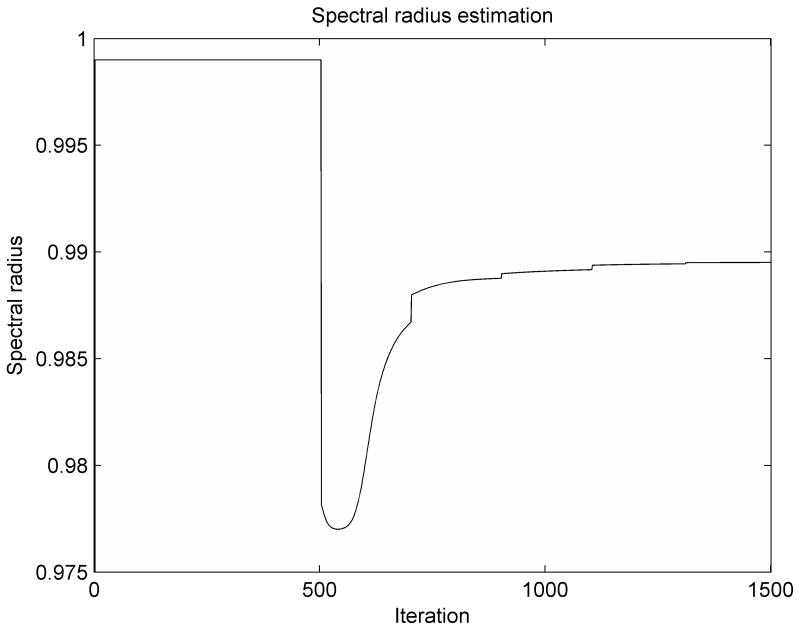
The variation of the spectral radius computed based on the adaptive estimation of the minimum eigenvalue, as presented in this paper, is shown in Figure 1. During the load application stage, the spectral radius is ρ = 0.999, corresponding to a low value for the damping coefficient. During the relaxation stage of the simulation, the computed value of the spectral radius converges steadily towards the optimal value. The computed value is always smaller than the optimal value, demonstrating that the estimated value for the minimum eigenvalue A0 is higher than the actual value (from equation 14), which is consistent with eqn. (20). The update of the linearization parameter qk and the corresponding nodal force vector (needed for the estimation of the lower eigenvalue in eqn. 21) is done every 200 iteration steps, being marked in Figure 1 by small jumps in the graph.
Figure 1.
The variation of the spectral radius computed based on the adaptive estimation of the minimum eigenvalue for the ellipsoid deformation experiment
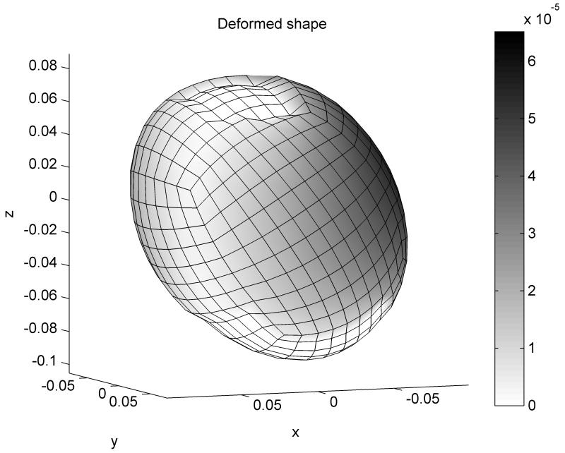
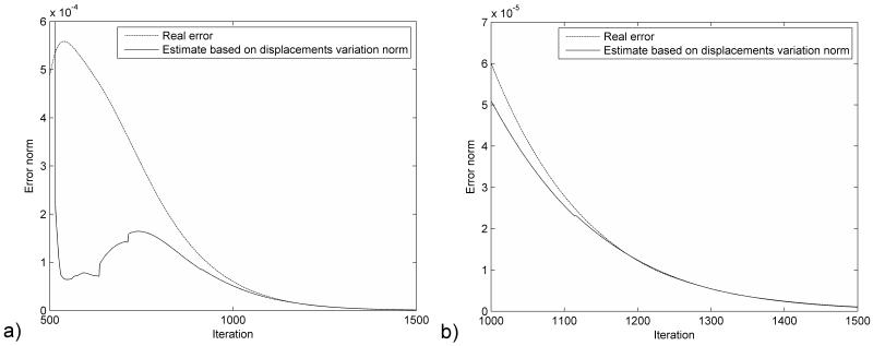
The distribution of the error (absolute difference in nodal position between the simulation results and the deformed state) after 1000 iteration steps is presented in Figure 2. The maximum error magnitude is around 0.06 mm. The error estimation based on eqn. (23) is compared with the real error in Figure 3. It is clear that the termination criteria does not offer a good estimation of the error at the beginning of the relaxation stage (after 500 iteration steps), as there is a big difference between the estimated value of the spectral radius and its true value. As the iteration number increases the error estimation is getting closer to the real error value (Figure 3.b). Therefore, the termination criteria should be used only after the estimated value of the spectral radius reaches a steady value (for example after 1100 iterations for this case, based on Figure 1). This can be checked during the iteration process.
Figure 2.
Distribution of error after 1000 iteration steps for the ellipsoid deformation experiment, presented in color code. All dimensions are in meters.
Figure 3.
Comparison of the real error with the error estimation based on the displacement variation norm for the ellipsoid deformation experiment a) Over the relaxation period b) Detail for the last 500 iterations.
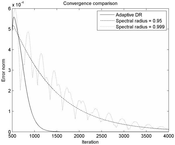
We present a comparison of the convergence properties of our adaptive DR procedure with the convergence properties of a DR procedure with fixed parameters in Figure 4. If the spectral radius is chosen too high (because of an under-estimation of the minimum eigenvalue in eqn. 14), the system is under-damped (eqn. 16), and therefore the low frequency oscillation modes are not eliminated fast enough. If the spectral radius is chosen too low, the system is over-damped, and therefore it moves very slowly towards the steady state solution. The spectral radius chosen using our adaptive procedure, which converges towards the optimum value, gives the fastest convergence towards the steady state solution, therefore ensuring shorter computation time.
Figure 4.
Convergence comparison between our adaptive DR method and a DR method with fixed parameters. The adaptive parameter estimation ensures fast convergence towards the steady state solution.
3.2. Simulation of a brain shift
A more complex simulation is presented here to demonstrate the computational efficiency of the proposed algorithm for highly nonlinear models. We use the same model as in [8], but we present it here again for completeness. A human brain consisting of healthy brain tissue, a tumor and ventricles is enclosed inside the skull. The different parts of the brain are modeled using nonlinear materials (Neo-Hookean) with different properties (Table 1). The material model is consistent with our previous work on brain material properties [19-21].
Table 1.
Material properties for different parts of the brain
| Brain part | Density (kg/m3) |
Young’s modulus (Pa) |
Poisson’s ratio |
|---|---|---|---|
| Brain | 1000 | 2500 | 0.49 |
| Tumor | 1000 | 7500 | 0.49 |
| Ventricle | 1000 | 100 | 0.1 |
The brain is meshed using mainly hexahedral elements but also includes some improved tetrahedral elements [22]. The mesh has 12182 elements and 13209 nodes (Figure 5). The skull is meshed using 3960 triangular elements. We assume that the initial geometry is known from high quality pre-operative MRI images and we simulate the brain shift by applying displacements on the area of the brain visible during craniotomy, where the displacements can be measured intra-operatively (using a laser range scanner [23] or a stereo vision system [24]). We extracted the required displacements from available intra-operative MRI images. A very similar model has been used in previous papers for brain shift estimation [14, 25, 26].
Figure 5.
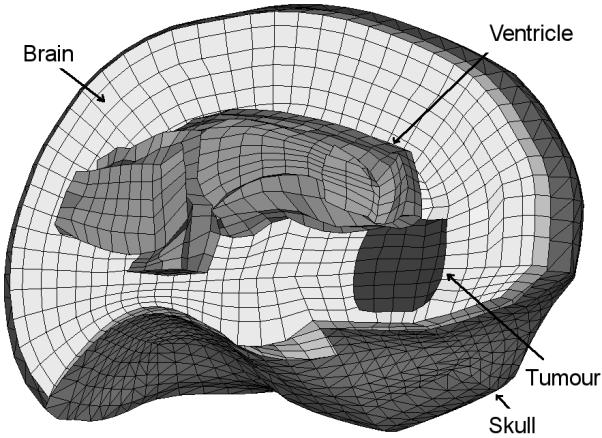
The mesh used for the brain shift simulation (only part of the mesh is shown).
The skull is assumed rigid and the interaction between the brain and the skull as a frictionless finite sliding contact. Because DR has the property of attenuating the high frequency vibrations in the solution, we can implement this contact as a computationally efficient kinematic constraint for the brain nodes (any brain node that penetrates the skull surface is brought back on the surface). All external brain nodes except the displaced ones are included in the contact definition. A detailed description of the contact algorithm used is presented in [17].
Similar to the ellipsoid deformation simulation, the deformed state was obtained by executing a large number of steps (10000). Because of the strong nonlinearity induced by the contact algorithm, the load (prescribed displacements) was applied over 1000 iteration steps.
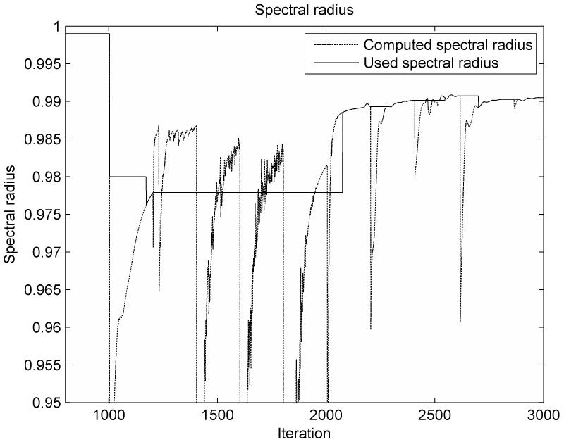
The computed value of the spectral radius, based on the proposed minimum eigenvalue estimation method, is presented in Figure 6. Because the movement of the brain surface nodes on the triangular mesh defining the skull is not smooth (a node can get trapped in a corner between triangles and then suddenly jump to a new position), the spectral radius estimation is not smooth over a large number of relaxation iterations. Therefore, we implemented a very simple updating algorithm: we check the computed spectral radius value against the value from the previous iteration; if the difference is small (less than 10E-4) for a number of successive iterations (we configured this number to 20), then we use this value in our computations, otherwise the value of the used spectral radius is not changed. The obtained spectral radius value is then used in equations (14) - (16) to compute the next iteration parameters. The used spectral radius value is presented in Figure 6.
Figure 6.
The variation of the spectral radius computed based on the adaptive estimation of the minimum eigenvalue for the brain shift experiment
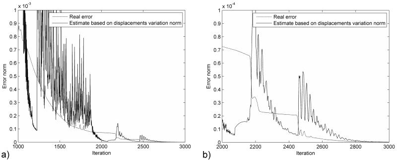
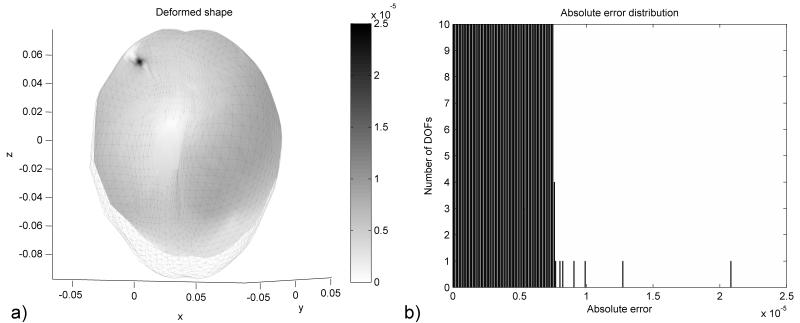
Similar to the previous experiment, the termination criteria can be trusted only after the computed value for the spectral radius starts to stabilize (around 2300 iterations). Nevertheless, even after the spectral radius stabilizes, there are a number of iterations for which the estimated error is much smaller than the real error (Figure 7.b), which can lead to an early termination of the computations. We studied in more detail what happens after 2400 iterations. The real error value is 2.08E-5 m, while the estimated error value is 7.8E-6 m. A distribution of the real error for all degrees of freedom (DOFs) in the model is presented in Figure 8.b. It can be seen that the real error value is determined by only one DOF, while the vast majority of DOFs have an error smaller than the estimated value. This behaviour is also an artefact of the contact algorithm, the node for which the maximum error is obtained being one of the nodes from the brain surface, as seen in Figure 8.a. The real error, computed using the infinity norm, is influenced by the outliers in the solution. The estimated error, based on eqn. 22, is not influenced by these outliers, and it represents better the overall accuracy of the solution.
Figure 7.
Comparison of the real error with the error estimation based on the displacement variation norm for the brain shift experiment a) Over the relaxation period b) Detail for the last 1000 iterations.
Figure 8.
Distribution of error after 2400 iteration steps for the brain shift experiment, presented a) in color code and b) as a histogram. All dimensions are in meters.
The proposed algorithm was implemented in C by modifying the Total Lagrangian Explicit Dynamics algorithm we presented in [27]. All simulations were done on a standard 3 GHz Intel® Core™ Duo CPU system using Windows XP operating system. Our implementation can perform 2000 iterations in 35s for the brain shift simulation, using a single CPU.
We also implemented the algorithm on GPU. We transferred all the computationally intensive parts of the algorithm (element force computation, displacement vector computation, contact handling, parallel reduction – including infinity norm computation and scalar product of vectors) to the GPU, to take advantage of its massive parallelism. We implemented the GPU code using NVIDIA’s Compute Unified Device Architecture (CUDA) [28] and the code was run on a NVIDIA Tesla C870 computing board, which has 16 multiprocessors with eight scalar processor cores each and single-precision floating point operations. A detailed description of the implementation can be found in [29]. The GPU implementation performs 2000 iterations of the brain shift simulation in 1.8s, offering real time computation capabilities. The use of single-precision floating-point numbers on the GPU does not have an impact on the convergence and accuracy of our solution method. This is a consequence of using the Total Lagrangian formulation, which does not exhibit accumulation of errors during the time stepping procedure.
4. Discussion and conclusions
In this paper we propose a fully adaptive Dynamic Relaxation procedure in the context of the Total Lagrangian formulation for finding the deformed state of a nonlinear finite element problem. The proposed method offers fast convergence, computational efficiency and the possibility to control the accuracy of the results. These characteristics make it an ideal method for solving image registration problems using bio-mechanical models.
In our previous paper [8] we estimated the value of the lower eigenvalue A0 during the pre-processing stage, by performing a supplementary simulation. In this paper we propose a new adaptive procedure for estimating this parameter, eliminating the need for any supplementary simulation. The two methods can be also combined in order to improve the convergence of the algorithm.
We adapt the termination criterion proposed in [8] to our new parameter estimation procedure. The termination criteria offers an indication about the absolute accuracy of the results based on the convergence properties of the method.
We present simulation results that confirm the convergence and computational efficiency of our adaptive method for highly nonlinear models. A GPU implementation of the algorithm can perform complex brain shift simulations in less than 2s.
Acknowledgements
The financial support of the Australian Research Council (Grant No. DP0343112, DP0664534 and LX0560460) and NIH (Grant No. 1-RO3-CA126466-01A1) is gratefully acknowledged.
Sponsors: Australian Research Council, Grant Numbers DP0343112, DP0664534 and LX0560460; NIH Grant Number 1-RO3-CA126466-01A1
Bibliography
- 1.Underwood P. In: Dynamic Relaxation, in Computational Methods for Transient Analysis. Belytschko T, Hughes TJR, editors. New-Holland; Amsterdam: 1983. pp. 245–265. [Google Scholar]
- 2.Barnes MR. Form-Finding And Analysis Of Prestressed Nets And Membranes. Computers and Strucrures. 1988;30(3):685–695. [Google Scholar]
- 3.Zhang LG, Yu TX. Modified Adaptive Dynamic Relaxation Method And Its Application To Elastic-Plastic Bending And Wrinkling Of Circular Plates. Computers and Structures. 1989;33(2):609–614. [Google Scholar]
- 4.Kashiwa M, Onoda J. Wrinkling Analysis Using Improved Dynamic Relaxation Method. American Institute of Aeronautics and Astronautics Journal. 2009;47(7) DOI: 10.2514/1.34031. [Google Scholar]
- 5.Salehi M, Aghaei H. Dynamic relaxation large deflection analysis of non-axisymmetric circular viscoelastic plates. Computers and Structures. 2005;83:1878–1890. [Google Scholar]
- 6.Pan L, Metzger D, Niewczas M. The Meshless Dynamic Relaxation Techniques for Simulating Atomic Structures of Materials; ASME Pressure Vessels and Piping Conference; Vancouver, BC, Canada. 2002. [Google Scholar]
- 7.Takeshi N, Takayoshi Y, Masaki N. The Behavior of Dynamic Relaxation in an Elastic Stroke Model for Character Recognition; Proceedings of the 4th International Conference on Document Analysis and Recognition; IEEE Computer Society. 1997. [Google Scholar]
- 8.Joldes GR, Wittek A, Miller K. Computation of intra-operative brain shift using dynamic relaxation. Computer Methods in Applied Mechanics and Engineering. 2009;198(41-44):3313–3320. doi: 10.1016/j.cma.2009.06.012. [DOI] [PMC free article] [PubMed] [Google Scholar]
- 9.Bathe K-J. Finite Element Procedures. Prentice-Hall; New Jersey: 1996. [Google Scholar]
- 10.Papadrakakis M. A Method for the Automated Evaluation of the Dynamic Relaxation Parameters. Computer Methods in Applied Mechanics and Engineering. 1981;25:35–48. [Google Scholar]
- 11.Ferrant M, Nabavi A, Macq B, Black PM, Jolesz FA, Kikinis R, Warfield SK. Serial registration of intraoperative MR images of the brain. Medical Image Analysis. 2002;6(4):337–359. doi: 10.1016/s1361-8415(02)00060-9. [DOI] [PubMed] [Google Scholar]
- 12.Warfield SK, Talos F, Tei A, Bharatha A, Nabavi A, Ferrant M, Black PM, Jolesz FA, Kikinis R. Real-time registration of volumetric brain MRI by biomechanical simulation of deformation during image guided surgery. Computing and Visualization in Science. 2002;5:3–11. [Google Scholar]
- 13.Warfield SK, Haker SJ, Talos I-F, Kemper CA, Weisenfeld N, Mewes UJ, Goldberg-Zimring D, Zou KH, Westin C-F, Wells WM, Tempany CMC, Golby A, Black PM, Jolesz FA, Kikinis R. Capturing intraoperative deformations: research experience at Brigham and Womens’s hospital. Medical Image Analysis. 2005;9(2):145–162. doi: 10.1016/j.media.2004.11.005. [DOI] [PubMed] [Google Scholar]
- 14.Wittek A, Miller K, Kikinis R, Warfield SK. Patient-Specific Model of Brain Deformation: Application to Medical Image Registration. Journal of Biomechanics. 2007;40:919–929. doi: 10.1016/j.jbiomech.2006.02.021. [DOI] [PubMed] [Google Scholar]
- 15.Miller K, Wittek A, Joldes G, Horton A, Roy TD, Berger J, Morriss L. Modelling brain deformations for computer-integrated neurosurgery. Communications in Numerical Methods in Engineering. 2009;26(1):117–138. [Google Scholar]
- 16.Joldes GR, Wittek A, Couton M, Warfield SK, Miller K. Real-Time Prediction of Brain Shift Using Nonlinear Finite Element Algorithms; Proceedings of the 12th MICCAI Conference; London, UK. 2009; [DOI] [PubMed] [Google Scholar]
- 17.Joldes GR, Wittek A, Miller K, Morriss L. Realistic And Efficient Brain-Skull Interaction Model For Brain Shift Computation; Computational Biomechanics for Medicine III Workshop, MICCAI; New-York. 2008. [Google Scholar]
- 18.Joldes GR, Wittek A, Miller K. Suite of finite element algorithms for accurate computation of soft tissue deformation for surgical simulation. Medical Image Analysis. 2009;13(6):912–919. doi: 10.1016/j.media.2008.12.001. [DOI] [PMC free article] [PubMed] [Google Scholar]
- 19.Miller K, Chinzei K. Constitutive modelling of brain tissue; Experiment and Theory. Journal of Biomechanics. 1997;30(11/12):1115–1121. doi: 10.1016/s0021-9290(97)00092-4. [DOI] [PubMed] [Google Scholar]
- 20.Miller K, Chinzei K, Orssengo G, Bednarz P. Mechanical properties of brain tissue in-vivo: experiment and computer simulation. Journal of Biomechanics. 2000;33:1369–1376. doi: 10.1016/s0021-9290(00)00120-2. [DOI] [PubMed] [Google Scholar]
- 21.Miller K, Chinzei K. Mechanical properties of brain tissue in tension. Journal of Biomechanics. 2002;35:483–490. doi: 10.1016/s0021-9290(01)00234-2. [DOI] [PubMed] [Google Scholar]
- 22.Joldes GR, Wittek A, Miller K. Non-locking Tetrahedral Finite Element for Surgical Simulation. Communications in Numerical Methods in Engineering. 2009;25(7):827–836. doi: 10.1002/cnm.1185. [DOI] [PMC free article] [PubMed] [Google Scholar]
- 23.Miga MI, Sinha TK, Cash DM, Galloway RI, Weil RJ. Cortical surface registration for image-guided neurosurgery using laser-range scanning. IEEE Transactions on Medical Imaging. 2003;22(8):973–985. doi: 10.1109/TMI.2003.815868. [DOI] [PMC free article] [PubMed] [Google Scholar]
- 24.Sun H, Farid H, Rick K, Hartov A, Roberts DW, Paulsen KD. Estimating Cortical Surface Motion Using Stereopsis for Brain Deformation Models; Medical Image Computing and Computer-Assisted Intervention - MICCAI 2003; Springer Berlin: Heidelberg. 2003.pp. 794–801. [Google Scholar]
- 25.Wittek A, Kikinis R, Warfield SK, Miller K. Brain shift computation using a fully nonlinear biomechanical model; 8th International Conference on Medical Image Computing and Computer Assisted Surgery MICCAI 2005; Palm Springs, California, USA. 2005; [DOI] [PubMed] [Google Scholar]
- 26.Wittek A, Hawkins T, Miller K. On the unimportance of constitutive models in computing brain deformation for image-guided surgery. Biomechanics and modeling in mechanobiology. 2009;8(1):77–84. doi: 10.1007/s10237-008-0118-1. [DOI] [PMC free article] [PubMed] [Google Scholar]
- 27.Miller K, Joldes GR, Lance D, Wittek A. Total Lagrangian Explicit Dynamics Finite Element Algorithm for Computing Soft Tissue Deformation. Communications in Numerical Methods in Engineering. 2007;23:121–134. [Google Scholar]
- 28.NVIDIA . CUDA Programming Guide Version 1.1. NVIDIA Corporation; Santa Clara, CA 95050: 2007. [Google Scholar]
- 29.Joldes GR, Wittek A, Miller K. Real-Time Nonlinear Finite Element Computations on GPU - Application to Neurosurgical Simulation. Computer Methods in Applied Mechanics and Engineering. 2010 doi: 10.1016/j.cma.2010.06.037. submitted for publication in June 2009. [DOI] [PMC free article] [PubMed] [Google Scholar]


