Abstract
A novel design of molecular buffer for molecule storage and delivery using a PANDA ring resonator is proposed. The optical vortices can be generated and controlled to form the trapping tools in the same way as the optical tweezers. In theory, the trapping force is formed by the combination between the gradient field and scattering photons, which is reviewed. By using the intense optical vortices generated within the PANDA ring resonator, the required molecules can be trapped and moved (transported) dynamically within the wavelength router or network, ie, a molecular buffer. This can be performed within the wavelength router before reaching the required destination. The advantage of the proposed system is that a transmitter and receiver can be formed within the same system, which is available for molecule storage and transportation.
Keywords: molecular buffer, molecular memory, molecular transceiver, molecular repeater, PANDA ring resonator
Introduction
Optical buffers are recognized as essential components in wavelength routers, in which the packets of data can be stored for resolving packet contention problems and also delay the outgoing packets.1,2 In practice, the optical router patents have been proposed and recorded,3–5 which can be useful for various applications. Recently, the promising techniques of microscopic volume trapping and transportation within the add/drop multiplexer have been reported in both theory6 and experiment,7 respectively, in which the transporter is known as an optical tweezer. Here, the optical tweezer generation technique has become a powerful tool for the manipulation of micrometer-sized particles. To date, the usefulness of static tweezers is well recognized. Moreover, the use of dynamic tweezers is now also understood in practical works.8–10 Schulz et al11 have shown that the transfer of trapped atoms between two optical potentials can be performed. In principle, optical tweezers use forces exerted by intensity gradients in the strongly focused beams of light to trap and move the microscopic volumes of matters, in which the other combination of force is induced by the interaction between photons, which is caused by photon scattering effects. In application, the field intensity can be adjusted and tuned, in which the desired gradient field and scattering force can form the suitable trapping force. Hence, the appropriate force can be configured for the transmitter/receiver, which can perform the long distance microscopic transportation.
In this paper, dynamic optical tweezers/vortices are generated using a dark soliton, bright soliton, and Gaussian pulse propagating within an add/drop optical multiplexer incorporating two nanoring resonators (PANDA ring resonator). The dynamic behaviors of solitons and Gaussian pulses are well described by Tasakorn et al.12 By using the proposed system, the transceiver can be integrated and performed by using a single device. Here, the use of the transceiver to form the transportation of microscopic volumes of matter, especially13 for molecule transportation in liquid core waveguide,14,15 drug delivery, and DNA transportation, in which the buffer is needed before reaching the required destination.
Theory
In operation, the trapping forces are exerted by the intensity gradients in the strongly focused beams of light to trap and move the microscopic volumes of matters, in which the optical forces are customarily defined by the relationship:16
| (1) |
Here Q is a dimensionless efficiency, nm is the refractive index of the suspending medium, c is the speed of light, and P is the incident laser power, measured at the specimen. Q represents the fraction of power utilized to exert force. For plane wave incidences on a perfectly absorbing particle, Q is equal to 1. To achieve stable trapping, the radiation pressure must create a stable, three-dimensional equilibrium. Because biological specimens are usually contained in aqueous media, the dependence of F on nm can rarely be exploited to achieve higher trapping forces. Increasing the laser power is possible, but only over a limited range due to the possibility of optical damage. Q itself is therefore the main determinant of trapping force. It depends upon the numerical aperture (NA), laser wavelength, light polarization state, laser mode structure, relative index of refraction, and the geometry of the particle.
Furthermore, in the Rayleigh regime, trapping forces decompose naturally into two components. Since, in this limit, the electromagnetic field is uniform across the dielectric, particles can be treated as induced point dipoles. The scattering force is given by:16
| (2) |
| (3) |
Here σis the scattering cross section of a Rayleigh sphere with radius r. 〈S〉 is the time averaged Poynting vector, n is the index of refraction of the particle, m = n/nm is the relative index, and k = 2πnm/λ is the wave number of the light. The scattering force is proportional to the energy flux and points along the direction of the propagation of the incident light. The gradient field (Fgrad) is the Lorentz force acting on the dipole induced by the light field. It is given by:16
| (4) |
where
| (5) |
is the polarizability of the particle. The gradient force is proportional and parallel to the gradient in energy density (for m > 1). The large gradient force is formed by the large depth of the laser beam. The stable trapping requires that the gradient force is in the −ẑ direction, which is against the direction of incident light (dark soliton valley). It is greater than the scattering force. By increasing the NA, when the focal spot size is decreased, the gradient strength is increased,16,17 which happens within a tiny system, for instance, a nanoscale device such as the nanoring resonator.
In our proposal, the trapping force is formed by using a dark soliton, in which the valley of the dark soliton is generated and controlled within the PANDA ring resonator by the control port signals. In this paper, we used the same theory of optical trapping and ring resonator, in which the simulation results and applications are differed from the previous work.18
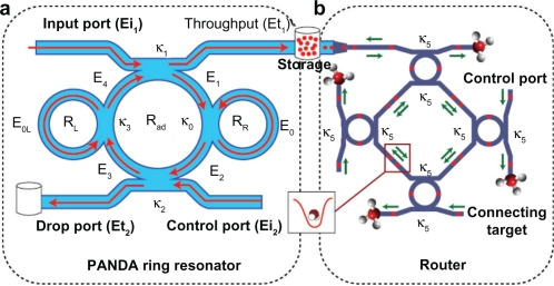
From Figure 1, the output field (Et1) at the through port is given by:19
| (6) |
where
- A
,
- B
,
- C
,
- D
, and
- F
.
Figure 1.
Schematic diagram of a buffer system, where (a) a PANDA ring resonator, (b) a wavelength router where Radd is the add/drop filter radius and RR and RL are the right and left ring resonator radii, respectively.
Here, Et and Ed represent the optical fields of the through port and drop ports, respectively. β = kneff is the propagation constant, neff is the effective refractive index of the waveguide, and the circumference of the ring is L = 2πR, where R is the radius of the ring. κ1 and κ2 are the coupling coefficients of the add/drop filters, kn = 2π/λ is the wave propagation number for in a vacuum, and the waveguide (ring resonator) loss is α = 0.5 dBmm−1. The fractional coupler intensity loss is γ = 0.1. In the case of the add/drop device, the nonlinear refractive index does not affect the system, therefore, it is neglected. The electric fields E0 and E0L are the field circulated within the nanoring at the right and left side of add/drop optical filter.
The power output (Pt1) at through port is written as:
| (7) |
The output field (Et2)at drop port is expressed as:19
| (8) |
where
- X
,
- Y =
The power output (Pt2) at drop port is:
| (9) |
In operation, the optical tweezers can be trapped, transported, and stored within the PANDA ring resonator and wavelength router, which can be used to form the microscopic volume (molecule) transportation and drug delivery via the waveguide,18 in which the manipulation of trapped microscopic volumes within the optical tweezers has been reported.
Molecular buffer
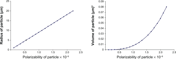
Molecular buffers are devices that can be used to store or delay atoms/molecules for a period of time (see Figure 2), where light intensity and velocity can also be controlled, which was described by Rosenberry et al20 and Lignie and Woerdman,21 available for medical application. Molecular buffers are a new device, which are operated in the same way as gas buffers.22 The polarizability of the particle is calculated by using equation (5), in this case, we assume that the sphere particle is polystyrene (n = 1.5894) and the liquid medium is water (n = 1.33), and the optical power which is required to trap particles of a certain size/polarizibility is 9.1W, which is the slope as shown in Figure 3A.
Figure 2.
Schematic of molecular buffer work in core wave guide.
Figure 3.
Graph of optical power which is required to trap the particle of a certain size/polarizability.
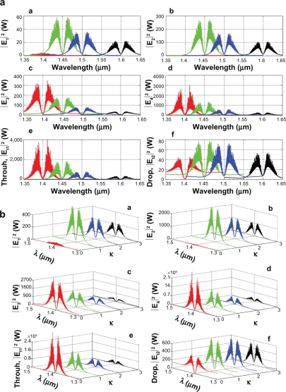
In simulation, the bright soliton with center wavelength at 1.50 μm, peak power 2W, pulse 35fs is input into the system via the input port, and the coupling coefficients are given as κ0 = 0.5, κ1 = 0.35, κ2 = 0.1, and κ3 = 0.35, respectively. The ring radii are Radd = 10 and 30 μm, RR = 50 and 100 nm, and RL = 50 and 100 nm, respectively. To date, the evidence of a practical device with a radius of 30 nm has been reported by Piyatamrong et al.19 Aeff are 0.50, 0.25, and 0.25 μm2. In this case, the dynamic tweezers (gradient fields) can be in the form of bright solitons, Gaussian pulses, and dark solitons, which can be used to trap the required microscopic volume. There are four different center wavelengths of tweezers generated; the dynamical movements are seen in Figure 4, where (a) |E1|2, (b) |E2|2, (c) |E3|2, (d) |E4|2, (e) through port, and (f) drop port signals, where in this case all microscopic volumes are received by the drop port. In practice, the fabrication parameters which can be easily controlled are the ring resonator radii instead of the coupling constants.
Figure 4.
Result of the dynamic tweezers within the buffer with different (a) wavelengths and (b) coupling constants, where Radd = 10 μm, RR = RL = 100 nm.
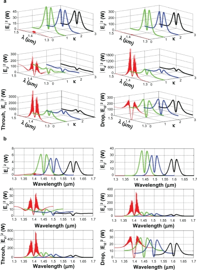
The important aspect of the result is that the tunable tweezers can be obtained by tuning (controlling) the add (control) port input signal, in which the required amount of microscopic volume (atom/photon/molecule) can be obtained and seen at the drop/through ports, otherwise they propagate within a PANDA ring before collapsing/decaying into the waveguide. More results of the optical tweezers generated within the PANDA ring are shown in Figure 5, where in this case, the bright soliton is used as the control port signal to obtain the tunable results. The output optical tweezers of the through and drop ports with different coupling constants are as shown in Figure 5A, while the different wavelength results are as shown in Figure 5B, which can be performed by the selected targets. In application, the trapped microscopic volumes (molecules) can move into the wavelength router via the through port, while the retrieved microscopic volumes are received via the drop port (connecting target). The advantage of the proposed system is that the transmitter and receiver can be fabricated on-chip and alternatively operated by a single device.
Figure 5.
Result of the dynamic tweezers within the buffer with different (a) coupling constants and (b) wavelengths, where Radd = 30 μm, RR = RL = 50 nm.
The magnitude of the optical trapping force is the pico Newton, which depends upon the relative refractive index of particle, which was given by Kumar et al.23 The particle radius was given by Hu et al,24 Fischer and Sørensen,25 and Nieminen et al,26 which is located in the cavity. It decreases with a reduction in refractive indices compared to the host medium.
Conclusion
We have proposed a new system that can be used to trap (delay) and transport molecules into an optical waveguide by using optical tweezers, which can be used for drug storage and as a delivery system. By utilizing the reasonable dark soliton input power, the dynamic tweezers can be controlled and stored (delayed) within the system before reaching the final destination. Tweezer amplification is also available by using the nanoring resonators, in which the signals can be modulated via the control port as shown in Figures 4B and 5A. In conclusion, we have shown that the use of a transceiver for long distance microscopic volume by using the proposed system, in which the drug delivery or molecular communication can be performed via the wavelength router to the required (connecting) targets. However, the problems of large microscopic volume and neutral matter may cause a problem, in which the pursuit of new guide pipes and media,27 for instance, nano tubes and specific gases, will be the issue of investigation.
Acknowledgments
We would like to thank the Institute of Advanced Photonics Science, Enabling Science and Nanotechnology (ESciNano) Research Alliance, UniversitiTeknologi Malaysia (UTM), and King Mongkut’s Institute of Technology (KMITL), Thailand for the support in providing the research facilities. This research work has been supported by the Ministry of Higher Education (MOHE), FRGS-grant 78452.
One of the authors (N Suwanpayak) would like to acknowledge King Mongkut’s Institute of Technology Ladkrabang, Bangkok (KMITL), Thailand for partial support in higher education at KMITL, Thailand.
Footnotes
Disclosure
The authors report no conflicts of interest in this work.
References
- 1.Cheng M, Wu C, Hiltunen J, Wang Y, Wang Q, Myllylä R. A variable delay optical buffer based on nonlinear polarization rotation in semiconductor optical amplifier. IEEE Photon Technol Lett. 2009;21(24):1885–1887. [Google Scholar]
- 2.Liu J, Lee TT, Jiang X, Horiguchi S. Blocking and delay analysis of single wavelength optical buffer with general packet size distribution. J Lightwave Technol. 2009;27(8):955–966. [Google Scholar]
- 3.Dragone CP. Improved waveguide grating optical router suitable for CWDM. Mar 9, 2009. Inventor. United States patent US2009035253.
- 4.Ham BS. Delayed optical router/switch. Sep 16, 2010. Inventor. United States patent US20100232792.
- 5.Oguchi K, Terada S, Hanawa M. Optical network system, optical router, fault recovery method of optical network, and program. Mar 18, 2010. Inventors. Japanese patent JP2010063009.
- 6.Piyatamrong B, Kulsirirat K, Mitatha ST, Yupapin PP. Dynamic potential well generation and control using double resonators incorporating in an add/drop filter. Mod PhysLett B. 2010;24(32):3071–3082. [Google Scholar]
- 7.Cai H, Poon A. Optical manipulation and transport of microparticle on silicon nitride microring resonator-based add-drop devices. Opt Lett. 2010;35(17):2855–2857. doi: 10.1364/OL.35.002855. [DOI] [PubMed] [Google Scholar]
- 8.Ashkin A, Dziedzic JM, Bjorkholm JE, Chu S. Observation of a single-beam gradient force optical trap for dielectric particles. Opt Lett. 1986;11(5):288–290. doi: 10.1364/ol.11.000288. [DOI] [PubMed] [Google Scholar]
- 9.Egashira K, Terasaki A, Kondow T. Photon-trap spectroscopy applied to molecules adsorbed on a solid surface: probing with a standing wave versus a propagating wave. App Opt. 2010;49(7):1151–1157. doi: 10.1364/AO.49.001151. [DOI] [PubMed] [Google Scholar]
- 10.Kachynski AV, Kuzmin AN, Pudavar HE, Kaputa DS, Cartwright AN, Prasad PN. Measurement of optical trapping forces by use of the two-photon-excited fluorescence of microspheres. Opt Lett. 2003;28(23):2288–2290. doi: 10.1364/ol.28.002288. [DOI] [PubMed] [Google Scholar]
- 11.Schulz M, Crepaz H, Schmidt-Kaler F, Eschner J, Blatt R. Transfer of trapped atoms between two optical tweezer potentials. J Mod Opt. 2007;54(11):1619–1626. [Google Scholar]
- 12.Tasakorn M, Teeka C, Jomtarak R, Yupapin PP. Multitweezers generation control within a nanoring resonator system. Opt Eng. 2010;49(7):075002. [Google Scholar]
- 13.Neuman K, Block SM. Optical trapping. Rev Sci Instrum. 2004;75(9):2787–2809. doi: 10.1063/1.1785844. [DOI] [PMC free article] [PubMed] [Google Scholar]
- 14.Parkin SJ, Knöner G, Nieminen TA, Heckenberg NR, Dunlop HR. Picoliterviscometry using optically rotated particles. Phys Rev E. 2007;76(4):1507–1512. doi: 10.1103/PhysRevE.76.041507. [DOI] [PubMed] [Google Scholar]
- 15.Wolfe DB, Conroy RS, Garsteck P, et al. Dynamic control of liquid-core liquid-cladding optical waveguides. Proc Natl Acad Sci. 2004;101(34):2434–2438. doi: 10.1073/pnas.0404423101. [DOI] [PMC free article] [PubMed] [Google Scholar]
- 16.Svoboda K, Block SM. Biological applications of optical forces. Annu Rev Biophys Biomol Struct. 1994;23:247–285. doi: 10.1146/annurev.bb.23.060194.001335. [DOI] [PubMed] [Google Scholar]
- 17.Zhu J, Ozdemir SK, Xiao YF, Li L, He L, Chen DR. On-chip single nanoparticle detection and sizing by mode splitting in an ultrahigh-Qmicroresonator. Nature Photon. 2010;4:46–49. [Google Scholar]
- 18.Suwanpayak N, Jalil MA, Teeka T, Ali J, Yupapin PP. Optical vortices generated by a PANDA ring resonator for drug trapping and delivery applications. Bio Med Opt Express. 2011;2(1):159–168. doi: 10.1364/BOE.2.000159. [DOI] [PMC free article] [PubMed] [Google Scholar]
- 19.Piyatamrong B, Kulsirirat K, Techitdheera W, Mitatha S, Yupapin PP. Dynamic potential well generation and control using double resonators incorporating in an add/drop filter. Mod Phys Lett B. 2010;24(32):3071–3082. [Google Scholar]
- 20.Rosenberry MA, Reyes JP, Tupa D, Gay TJ. Radiation trapping in rubidium optical pumping at low buffer-gas pressures. Phys Rev A. 2007;75(2):3401–3407. [Google Scholar]
- 21.Lignie MC, Woerdman JP. Light-induced drift of Na in molecular buffer gases. J Phy B: At Mol Opt Phys. 1990;23(3):417–426. [Google Scholar]
- 22.Waggoner PS, Palmer JS, Antonov VN, Weaver JH. Metal nanostructure growth on molecular buffer layers of CO2. Surf Sci. 2005;596(1–3):12–20. [Google Scholar]
- 23.Kumar R, Shakher C, Mehtac DS. 3D Multiple optical trapping of Au-nanoparticles and prokaryote E. coli using intra-cavity generated non circular beam of inhomogeneous intensity. Laser Phys. 2010;20(6):1514–1524. [Google Scholar]
- 24.Hu J, Lin S, Kimerling LC, Crozier K. Optical trapping of dielectric nanoparticles in resonant cavities. Phys Rev A. 2010;82(5):3819–3826. [Google Scholar]
- 25.Fischer M, Sørensen KB. Calibration of trapping force and response function of optical tweezers in viscoelastic. J Opt A: Pure Appl Opt. 2007;9(8):239–250. [Google Scholar]
- 26.Nieminen TA, Dunlop HR, Heckenberg NR. Calculation and optical measurement of laser trapping forces on non-spherical particles. J Quant Spectr Rad Transf. 2001;70(4–6):627–637. [Google Scholar]
- 27.Ashkin A. Optical trapping and manipulation of neutral particles using lasers. Proc Natl Acad Sci. 1997;94(10):4853–4860. doi: 10.1073/pnas.94.10.4853. [DOI] [PMC free article] [PubMed] [Google Scholar]


