

Abstract
The study was approved by the animal care and use committee. The purpose of the study was to prospectively establish proof of principle in vivo in canines for a magnetic resonance (MR) imaging–compatible robotic system designed for image-guided prostatic needle intervention. The entire robot is built with nonmagnetic and dielectric materials and in its current configuration is designed to perform fully automated brachytherapy seed placement within a closed MR imager. With a 3.0-T imager, in four dogs the median error for MR imaging–guided needle positioning and seed positioning was 2.02 mm (range, 0.86–3.18 mm) and 2.50 mm (range, 1.45–10.54 mm), respectively. The robotic system is capable of accurate MR imaging–guided prostatic needle intervention within a standard MR imager in vivo in a canine model.
© RSNA, 2008
Because of its good perineal and transrectal accessibility and its relatively fixed position, the prostate is an excellent target for image-guided interventions, such as brachytherapy or biopsy. The success of image-guided intervention depends primarily on the quality of the image used for guidance and on the ability to accurately deploy the procedure instrument to the desired target. Magnetic resonance (MR) imaging with its superb soft-tissue contrast and its multiplanar capabilities has the best visualization of the prostate and its surrounding anatomy (1). The principal limitations to a more widespread adoption of MR imaging for prostate image-guided intervention are the complex and challenging environment inherent to MR imaging technology and the constrained ergonomics of closed-bore imagers (2). Attempts to improve patient access within the imager typically result in a trade-off between patient accessibility and signal-to-noise ratio. Thus far, to our knowledge, only a limited number of centers have reported their experience with MR imaging–guided prostatic intervention (3–6).
A robot capable of interacting with the patient inside a closed-bore MR imager could offer a solution to most of these problems. Furthermore, as a digital device, a robot is ideally suited to accurately align an instrument to any point in the three-dimensional coordinate system of the MR image. It is therefore conceivable that an MR imaging–guided robot could improve the quality of diagnostic and therapeutic image-guided intervention of the prostate.
We have conceptualized and manufactured a fully MR imaging– compatible robotic system designed to perform MR imaging–guided transperineal needle intervention of the prostate (7). Thus, the purpose of our study was to prospectively establish proof of principle in vivo in canines for an MR imaging–compatible robotic system we have designed for image-guided prostatic needle intervention.
MATERIALS AND METHODS
One author (M.S.) is an employee of Philips Medical Systems (Cleveland, Ohio), the manufacturer of equipment used in our study. All other authors who are not employees of Philips had full control of the inclusion of any data or information that might have presented a conflict of interest for the author who is an employee of Philips.
The Robotic System
The system consists of the robot and its controller unit (Fig 1). The controller unit includes a computer, motion control elements, a series of electropneumatic and electro-optical interfaces, and a brachytherapy seed magazine and delivery system. It is located outside the MR imaging room and is connected to the robot by plastic hoses, which are 6 m in length and carry air and fiber-optic wires. The robot itself fits into a standard closed-bore MR imager, and it is designed to interact with the patient within the imager. To achieve full MR imaging compatibility, the entire robot is built of nonmagnetic and dielectric materials, such as fiber glass, ceramics, plastics, and rubber (7). The only metallic part of the robot is the MR imaging–compatible titanium needle.
Figure 1:
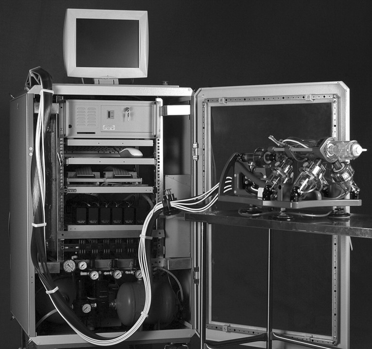
Robot (right) and controller unit (left) are connected with 6-m-long pneumatic hoses and optic fibers.
Furthermore, a pneumatic actuator was specifically developed for this application. Unlike other types of pneumatic motors, this actuator uses a stepper motor's principle of operation and thereby achieves high precision in a safe and easily controllable manner (8). The linear size of one step is 0.055 mm. Pressure waves are used to set the motors in motion. These waves are created by a pneumatic distributor remotely located in the controller unit and are transmitted to the robot through the plastic hoses. The actuation is encoded by using fiber optics; the motors use pressured air and light but no electricity whatsoever. These features prevent the robot from creating any interference with the electromagnetic environment inherent to MR imaging technology (7).
To meet standard safety requirements for the use in medical applications, the robot's motors are designed for fail-safe operation. Any form of malfunction leads to a lock and cannot result in uncontrolled motion beyond the size of one step (0.055 mm).
The motors provide the robot with five degrees of freedom (Fig 2) to place and orient an end effector as desired (Fig 3). The present end effector has one additional controlled degree of freedom to set the depth of needle insertion and three end-of-stroke degrees of freedom to manipulate a titanium needle (18 gauge, 15 cm long) and to deploy brachytherapy seeds automatically. So far, this is the only end effector that has been developed. However, the end effector is easily detachable from the robot and could be replaced with other end effectors (for other percutaneous interventions) in the future.
Figure 2:

Schematic diagram of robot illustrates the five degrees of freedom: translation (T) along the x-, y-, and z-axes, as well as rotation (R) around x- and y-axes.
Figure 3:

Pneumatic stepper motors (long arrows) orient end effector (short arrows) as desired.
Robot Registration
To align the end effector to a desired target on the MR image, it is necessary to register the position of the robot in the MR imager and to compute six degrees of freedom registration confirmation from the coordinate system of the robot to the coordinate system of the image. To do this, a special registration marker was developed. The marker has a continuous shape and is composed of an ellipse and a line (Fig 4). This structure was chosen as being the best to fit our robotic end effector. Results of previous studies have shown that markers with a continuous structure (9,10) provide better registration accuracy than point markers (11).
Figure 4:

A, An ellipse (long arrow), a line (dashed arrow), and four balls (short arrow) are embedded in the end effector of the robot as registration markers. B, Maximum intensity projection MR image of these markers.
Once the robot was fixed within the imager, an initial scout image with a coarse resolution was obtained. The position of the markers was then registered with a transverse three-dimensional gradient-echo acquisition by using the following parameters: repetition time msec/echo time msec, 7.7/2.3; field of view, 100 mm; matrix, 192 × 256; 60 sections with a section thickness of 3 mm; acquired voxel size, 0.52 × 0.52 × 3 mm; reconstructed voxel size, 0.39 × 0.39 × 3 mm; acquisition bandwidth, 687 Hz/pixel; two signals acquired to suppress aliasing; and imaging duration, 180 seconds. The acquired volume was then exported in Digital Imaging and Communications in Medicine format to a personal computer. The intersections of the markers with the planes of the MR sections were automatically identified, and the registration transformation from the robot to the image was constructed by using an automatic registration algorithm. This registration algorithm was previously developed and tested, and it works with an intrinsic registration accuracy of less than 1 mm (12).
Animal Tests
Our study was approved by the animal care and use committee of our institution. The experiments were performed in four male dogs that weighed between 25 and 30 kg each. After intravenous induction, anesthesia was maintained with continuous inhalation of 1%–3% isoflurane by using an MR imaging–compatible anesthesia machine. The animal was continuously monitored throughout the procedure.
The dog was placed on a padded holder and secured in position (Fig 5) on the table of a 3.0-T imager (Achieva XMR; Philips Medical Systems, Best, the Netherlands). The perineum was shaved, and the skin was prepared and draped in the usual fashion. One 10-mm skin incision was created in the midline of the perineum about 3 cm anterior to the anus. The robot was then brought and secured into place on the MR imager table, with its nozzle inserted through the incision in the dog's perineum. Next, a 20-cm coil (SENSE Flex-L; Philips Medical Systems) was secured into place with one element underneath and one element on top of the dog, which covered the prostatic region of the dog as well as the registration markers of the robot. After registration of the robot in the MR imager, the coil was moved to include the entire prostate as needed and imaging of the dog's pelvis was performed with a T2-weighted multisection multi-spin-echo sequence with the following acquisition parameters: 7563/80; spin echo factor, 16; echo spacing, 9.4 msec; field of view, 230 mm; matrix, 304 × 240; 34 sections with a section thickness of 1.0 mm; acquired voxel size, 0.76 × 0.96 × 1.0 mm; reconstructed voxel size, 0.45 × 0.45 × 1.0 mm; bandwidth, 215 Hz/pixel; two signals acquired to suppress aliasing; and imaging duration, 470 seconds. The acquired volume was then exported in Digital Imaging and Communications in Medicine format to a personal computer, and custom software was used to define the targets and the entry points for the needle on the three-dimensional coordinate system of the MR image. The same software was used to calculate the coordinates for the respective positions in the coordinate system of the robot.
Figure 5:

One of the study animals is being prepared for the procedure. Robot is attached to MR imager table with suction cups. Robot can either be mounted vertically (as depicted) or horizontally, depending on the best fit for the individual setup.
In the first volume, the desired needle entry point on the perineum and the target for the first seed in the prostate were selected in a way that neither the rectum nor the urethra would be affected by the needle trajectory. Even though the nozzle of the robot's end effector was already inserted through the skin incision, the elasticity of the skin allowed translational movements at the skin entry point of up to 2 cm in each direction of the horizontal and vertical axis. The respective coordinates were then sent to the controller unit, and after the robot was aligned to the requested position and the appropriate depth of needle insertion was set, the needle was deployed to the desired target at a speed of 1–1.5 m/sec. With the needle inserted, a second MR imaging acquisition was obtained with the same parameters to determine the position of the needle point. At that point, a nonradioactive brachytherapy dummy seed (Mick Radio-Nuclear Instruments, Mount Vernon, NY) with a diameter of 0.8 mm and a length of 4.76 mm was automatically deployed through the needle at the same target. After that, the needle was retracted, and a third MR imaging acquisition was obtained by using the previous parameters to localize the implanted seed (Fig 6). This last acquisition was also used to specify the next target position. Depending on the dog's prostate size, up to six seeds were implanted per animal, which stayed in the same position in the bore of the imager for the whole procedure. After anesthesia, heart rate and gag reflex were monitored for about 2 hours until the dog was extubated and ambulatory. All experiments were completed successfully. The four dogs survived the procedure without complications, and they continued to do well for the next several days they remained in our care.
Figure 6:

Transverse MR images of a dog's pelvis as seen with targeting software. A, Target image. Desired target is marked by the small dot at the intersection of the lines. B, Image obtained after needle has been shot at desired target. The black spot (arrow) is an artifact produced by needle point. C, Image obtained after dummy seed (arrow) has been deployed.
Data Evaluation
The positioning errors for each needle placement and each seed placement were evaluated separately on the three-dimensional coordinate system of the MR image. At the respective MR imaging acquisition, the position of the needle point or the seed was determined with a hand caliper independently by two reviewers (M.M. and A.P., 5 and 2 years of experience with prostate MR imaging, respectively) by using the same custom software as used for targeting. The average of the values determined by the reviewers was used as the “actual position” for all calculations. The needle point produced an artifact on MR images that was typically 5 × 3 × 3 mm in size (Fig 6). The configuration of the artifact was symmetric around the trajectory of the needle. For our evaluation, we defined the position of the needle point at the center of this artifact. The seed position was defined at the center of the seed on the MR image. The positioning error was defined as the norm (square root of the sum of the vector components squared) of the vector (in millimeters) between the desired position (target) and the actual position. Additionally, the difference between the needle point position and the seed position was determined (in millimeters) for every axis (x, y, z), where x and y are coordinates in the image section, and z measures the depth of sections.
The time for the registration, as well as each seed placement, was recorded by one of the authors (A.P.), and all images were subjectively evaluated for artifacts produced by the robot (M.M., A.P., and M.S. by consensus reading).
RESULTS
Time
The registration of the robot in the MR imager was typically accomplished within 10 minutes. All attempted seed placements were successful. Within the study conditions outlined above, the time requirement to place one seed was between 20 and 25 minutes. The greater part of the time was used for the two MR imaging acquisitions, and most of the rest was spent planning the next target position. The actual deployment of the seed was performed by the robot in a fully automated fashion in 5 seconds. Apart from the registration markers, the robot was invisible to the MR imager and did not produce any noticeable artifacts.
Needle and Seed Placement
In two dogs six seeds were placed, in one dog four seeds were placed, and in one dog only two seeds were placed, for a total of 18 implanted seeds. Accordingly, 18 needle positions and 18 seed positions were acquired and compared with the respective target points. For needle positioning, the median error was 2.02 mm (range, 0.86–3.18 mm) (Fig 7). For seed positioning, the median error was 2.50 mm (range, 1.45–10.54 mm) (Fig 8). The median difference between the position of the needle point and the seed position was 0.34 mm (range, −1.78 to 4.94 mm), 0.00 mm (range, −1.80 to 3.47 mm), and −3.06 mm (range, −11.31 to 1.72 mm) in the x-, y-, and z-axes, respectively.
Figure 7:

Histogram shows distribution of needle placement error (n = 18). For the majority of the needle positions, placement error is between 1.5 and 2.5 mm.
Figure 8:

Histogram shows distribution of seed placement error (n = 18). For the majority of the seeds, placement error is between 1 and 3 mm; however, for six seeds, placement error is more than 5 mm.
DISCUSSION
In our study, we establish the proof of principle for a fully automated, MR imaging–guided prostatic needle intervention in vivo in a canine model. Our robotic system is capable of very precise needle positioning with MR imaging guidance within a standard closed-bore MR imager. This obviates the necessity of moving the patient in and out of the bore for imaging and manipulations, respectively.
Our results were consistent with the results we acquired in the extensive preliminary testing of the system, where the robot reliably performed with submillimeter accuracy in ex vivo models (13). In our study data, there is a noticeable difference between needle positioning errors and seed positioning errors, and the greatest difference was measured in the z-axis. The z-axis is not perfectly aligned to, but is most consistent with, the direction of needle insertion, which suggests that tissue deflection and seed migration along the puncture channel account for most of the recorded errors.
To minimize tissue and needle deflection, we inserted the tip (nozzle) of the robot through a small perineal incision to avoid the needle piercing through the skin. Additionally, the needle was deployed at the target with high velocity. To improve seed placement precision, the prostate could be anchored with two or more percutaneously placed needles, as is routinely done during conventional prostate brachytherapy, and the needle position could also be adjusted in the needle axis if tissue deformation is recognized. However, this was not done in our proof-of-principle study.
Compared with clinical instances of prostate brachytherapy, seed placement in our study was very time consuming. Yet, for the proof of principle of this technology, time was not a critical issue. Seed placement is considerably faster if MR imaging acquisitions are not obtained as often, and in our study we performed imaging after each needle and each seed was placed to evaluate the magnitude and source of the errors.
Limitations of our study included the fact that the positioning errors were defined in image coordinates. The reported errors characterize intrinsic system error and needle deflection error. This method, however, does not factor in the error due to tissue deflection. Optimally, the target and the seed coordinates should be defined in a prostate-attached coordinate system, and deformable registration may be used to compute the transformation of the prostate between the target definition images and seed verification images. This way, the error would be relative to anatomic structures that can move during treatment. While this would be the ideal way of determining positioning errors, deformable registration is still an active research topic with no universally accepted algorithms. Moreover, even though we imaged at a high spatial resolution (0.45 × 0.45 × 1.0 mm), the resolution of the MR image inherently adds to the uncertainty in the needle and seed position errors.
A few centers have reported their experience with MR imaging–guided prostatic intervention. One group of investigators performed MR imaging–guided prostate brachytherapy and prostate biopsy (4,14,15). They used a transperineal approach with an open low-field-strength (0.5-T) MR imager and correlated the interventional MR images to images previously acquired with a 1.5-T imager. Recently, authors from the same group (16) reported on a robotic manipulator designed to position a guide for MR imaging–controlled manual needle insertion. Other groups (3,17,18) have reported on transperineal and transrectal MR imaging–guided prostate intervention within high-field-strength closed-bore imagers. These authors have used custom-built MR imaging–compatible needle guides or templates to assist the physician in the placement of the needles.
Our robotic system coregisters with the coordinate system of the MR imager to perform fully automated manipulations directed from a computer workstation outside the MR imaging room. The key technology of the system is a pneumatic stepper motor (8), which is completely compatible with the electromagnetic environment of the MR imager and allows for very precise actuation within the imager. Previous research in this field has commonly relied on piezoelectric motors (19–21). These provide no magnetic interference but employ high-frequency electric currents creating image distortion if operated closer than 0.5 m from the MR imaging isocenter (20). This is not an issue with our pneumatic motors.
Because of the modular structure of the robot, it is easy to exchange the current seed placing end effector with one designed for a different procedure. Alternative end effectors can be designed to perform biopsies, inject liquid agents, and insert cryotherapy or radiofrequency probes. Even though extensive further testing is needed, it is conceivable that a device like our robotic system could improve the performance of a number of diagnostic and therapeutic image-guided interventions. Furthermore, the robot could play an important role in the validation and application of new imaging modalities and targeted procedures emerging for diagnosis and therapy of prostatic disease.
ADVANCES IN KNOWLEDGE
-
•.
We present a fully MR imaging–compatible robotic system designed to perform automated, image-guided, prostatic needle intervention within a closed-bore MR imager.
-
•.
With a standard 3.0-T imager, the median error for MR imaging–guided prostatic needle positioning and seed positioning in vivo in a canine model is 2.02 mm and 2.50 mm, respectively.
IMPLICATION FOR PATIENT CARE
-
•.
Even though extensive further testing is needed, it is conceivable that a device like our robotic system could improve the performance of a number of diagnostic and therapeutic image-guided interventions.
Our robotic system is capable of very precise needle positioning with MR imaging guidance within a standard closed-bore MR imager.
Footnotes
See Materials and Methods for pertinent disclosures.
The contents are solely the responsibility of the authors and do not necessarily represent the official views of the NIH or the PCF.
Author contributions: Guarantor of integrity of entire study, D.S.; study concepts/study design or data acquisition or data analysis/interpretation, all authors; manuscript drafting or manuscript revision for important intellectual content, all authors; manuscript final version approval, all authors; literature research, M.M., A.P., D.S.; experimental studies, all authors; statistical analysis, A.P.; and manuscript editing, all authors
References
- 1.Yu KK, Hricak H. Imaging prostate cancer. Radiol Clin North Am 2000;38:59–85. [DOI] [PubMed] [Google Scholar]
- 2.Atalar E, Menard C. MR-guided interventions for prostate cancer. Magn Reson Imaging Clin N Am 2005;13:491–504. [DOI] [PubMed] [Google Scholar]
- 3.Beyersdorff D, Winkel A, Hamm B, Lenk S, Loening SA, Taupitz M. MR imaging-guided prostate biopsy with a closed MR unit at 1.5 T: initial results. Radiology 2005;234:576–581. [DOI] [PubMed] [Google Scholar]
- 4.D'Amico AV, Cormack R, Tempany CM, et al. Real-time magnetic resonance image-guided interstitial brachytherapy in the treatment of select patients with clinically localized prostate cancer. Int J Radiat Oncol Biol Phys 1998;42:507–515. [DOI] [PubMed] [Google Scholar]
- 5.Kaplan I, Oldenburg NE, Meskell P, Blake M, Church P, Holupka EJ. Real time MRI-ultrasound image guided stereotactic prostate biopsy. Magn Reson Imaging 2002;20:295–299. [DOI] [PubMed] [Google Scholar]
- 6.Krieger A, Susil RC, Menard C, et al. Design of a novel MRI compatible manipulator for image guided prostate interventions. IEEE Trans Biomed Eng 2005;52:306–313. [DOI] [PMC free article] [PubMed] [Google Scholar]
- 7.Stoianovici D, Song D, Petrisor D, et al. “MRI Stealth” robot for prostate interventions. Minim Invasive Ther Allied Technol 2007;16:241–248. [DOI] [PMC free article] [PubMed] [Google Scholar]
- 8.Stoianovici D, Patriciu A, Mazilu D, Petrisor D, Kavoussi L. A new type of motor: pneumatic step motor. IEEE/ASME Trans Mechatron 2007;12:98–106. [DOI] [PMC free article] [PubMed] [Google Scholar]
- 9.Lee S, Fichtinger G, Chirikjian GS. Numerical algorithms for spatial registration of line fiducials from cross-sectional images. Med Phys 2002;29:1881–1891. [DOI] [PubMed] [Google Scholar]
- 10.Susil RC, Anderson JH, Taylor RH. A single image registration method for CT guided interventions. In: Medical Image Computing and Computer-Assisted Intervention, MICCAI'99, Proceedings, 1999; 798–808.
- 11.Fitzpatrick JM, West JB, Maurer CR Jr. Predicting error in rigid-body point-based registration. IEEE Trans Med Imaging 1998;17:694–702. [DOI] [PubMed] [Google Scholar]
- 12.Patriciu A, Petrisor D, Muntener M, Mazilu D, Schaer M, Stoianovici D. Automatic brachytherapy seed placement under MRI guidance. IEEE Trans Biomed Eng 2007;54:1499–1506. [DOI] [PMC free article] [PubMed] [Google Scholar]
- 13.Muntener M, Patriciu A, Petrisor D, et al. Magnetic resonance imaging compatible robotic system for fully automated brachytherapy seed placement. Urology 2006;68:1313–1317. [DOI] [PMC free article] [PubMed] [Google Scholar]
- 14.D'Amico AV, Cormack RA, Tempany CM. MRI-guided diagnosis and treatment of prostate cancer. N Engl J Med 2001;344:776–777. [DOI] [PubMed] [Google Scholar]
- 15.D'Amico AV, Tempany CM, Cormack R, et al. Transperineal magnetic resonance image guided prostate biopsy. J Urol 2000;164:385–387. [PubMed] [Google Scholar]
- 16.Dimaio SP, Pieper S, Chinzei K, et al. Robot-assisted needle placement in open-MRI: system architecture, integration and validation. Stud Health Technol Inform 2006;119:126–131. [PubMed] [Google Scholar]
- 17.Menard C, Susil RC, Choyke P, et al. MRI-guided HDR prostate brachytherapy in standard 1.5T scanner. Int J Radiat Oncol Biol Phys 2004;59:1414–1423. [DOI] [PMC free article] [PubMed] [Google Scholar]
- 18.Susil RC, Menard C, Krieger A, et al. Transrectal prostate biopsy and fiducial marker placement in a standard 1.5T magnetic resonance imaging scanner. J Urol 2006;175:113–120. [DOI] [PMC free article] [PubMed] [Google Scholar]
- 19.Chinzei K, Miller K. Towards MRI guided surgical manipulator. Med Sci Monit 2001;7:153–163. [PubMed] [Google Scholar]
- 20.Hempel E, Fischer H, Gumb L, et al. An MRI-compatible surgical robot for precise radiological interventions. Comput Aided Surg 2003;8:180–191. [DOI] [PubMed] [Google Scholar]
- 21.Tsekos NV, Ozcan A, Christoforou E. A prototype manipulator for magnetic resonance-guided interventions inside standard cylindrical magnetic resonance imaging scanners. J Biomech Eng 2005;127:972–980. [DOI] [PubMed] [Google Scholar]