Abstract
An asymmetric stent with low porosity patch across the intracranial aneurysm neck and high porosity elsewhere is designed to modify the flow to result in thrombogenesis and occlusion of the aneurysm and yet to reduce the possibility of also occluding adjacent perforator vessels. The purposes of this study are to evaluate the flow field induced by an asymmetric stent using both numerical and digital subtraction angiography (DSA) methods and to quantify the flow dynamics of an asymmetric stent in an in vivo aneurysm model. We created a vein-pouch aneurysm model on the canine carotid artery. An asymmetric stent was implanted at the aneurysm, with 25% porosity across the aneurysm neck and 80% porosity elsewhere. The aneurysm geometry, before and after stent implantation, was acquired using cone beam CT and reconstructed for computational fluid dynamics (CFD) analysis. Both steady-state and pulsatile flow conditions using the measured waveforms from the aneurysm model were studied. To reduce computational costs, we modeled the asymmetric stent effect by specifying a pressure drop over the layer across the aneurysm orifice where the low porosity patch was located. From the CFD results, we found the asymmetric stent reduced the inflow into the aneurysm by 51%, and appeared to create a stasis-like environment which favors thrombus formation. The DSA sequences also showed substantial flow reduction into the aneurysm. Asymmetric stents may be a viable image guided intervention for treating intracranial aneurysms with desired flow modification features.
Keywords: Stent, Aneurysm, Digital Subtraction Angiography, Computational Fluid Dynamics, Image guided interventions, CT, image-based finite element models of physiology, image-based biomechanical models, circulation, porosity, wall shear stress
1. INTRODUCTION
Endovascular coiling in patients with ruptured intracranial aneurysms has been found to be significantly better than neurosurgical clipping in the short term studies 1. However, one of the limitations of coil embolization of aneurysms is it cannot effectively obliterate the wide-necked or fusiform lesions 2. Recent studies on using stents to cover the aneurysm neck have achieved promising results3–5. Endovascular stenting across the intracranial aneurysm orifice is believed to favorably disturb the flow to cause aneurysmal thrombosis. In an in vivo study to investigate the outcome of stenting in an animal aneurysm model, Krings et al.4 placed porous stents alone, stent-grafts, and stent with coils in elastase-induced animal models. They found that porous stents or stents with coil-treated aneurysms could result in in-stent stenosis, coil compaction and regrowth of aneurysm, whereas stent-grafts led to complete and stable aneurysm obliteration4.
However, ideally when an intracranial stent excludes the aneurysm from the circulation, it should also leave the adjacent perforators open to prevent adverse outcome. The first requires a low porosity stent, whereas the second requires high porosity. In a study to determine the probability of blockage of perforators by stent struts, Yang et al.6 showed that the probability of commercial stents, with porosity of 80%, blocking a 100 µm perforator was approximately 20%. Thus, instead of inducing thrombosis in an intracranial aneurysm, placing a stent may also induce adverse effects of blocking the perforators. In addition, stents should also impede the flow impingement on the aneurysm wall, which is believed to lead to aneurysm dilation and continuous growth. Such flow impingement is also believed to increase the risk of coil compaction or coil herniation into the parent vessel in coiled-treated aneurysms, and later induction of aneurysm regrowth or recanalization3, 7, 8. Since commercial stents are designed to hold the vessel opened, these types of high porosity (approximately 70–80%) stents are not designed to obliterate the aneurysm by isolating it from the circulation. Therefore, an asymmetric stent with low porosity across the aneurysm neck and high porosity elsewhere would potentially be ideal in treating the aneurysm.
Although multiple in vitro and numerical studies have quantified the flow patterns of stented aneurysms, the majority of these studies used an idealized two-dimensional (2D) or three-dimensional (3D) stented aneurysm geometry9–17. Previously, Lieber et al.16 found that flow modification in an aneurysm is influenced by different stent parameters such as porosity or a stent’s wire dimensions. Thus, stent geometry becomes an important set of design parameters in aneurysmal stenting. The flow characteristics and the biological consequences that a particular stent will generate in the treatment of aneurysms are currently unclear. Previous in vitro experimental study of asymmetric stents revealed that the magnitude of wall shear stress was reduced by 2 orders of magnitude and inflow to the aneurysm cavity was reduced linearly with decreasing permeability18. In addition, compared with the use of coils, the use of asymmetric stents led to marked flow modification, as seen with imaging sequences, and substantially slower inflow, as indicated by time-density curves, owing to the low-porosity region of the stent that covers the aneurysm orifice19–21.
Due to complex stent geometry and expensive computational costs, there are only a few computational studies that have examined the effects of stenting on the hemodynamics in aneurysms and these were with 3D idealized geometries9, 14. The evaluation of different types of stent designs in realistic aneurysm hemodynamics is challenging. To improve the feasibility of asymmetric stent treatment in intracranial aneurysms, we evaluated an asymmetric stent in an in vivo aneurysm animal model and quantified the flow field induced by an asymmetric stent with computational fluid dynamics (CFD) modeling techniques with qualitative validation by digital subtraction angiography.
2. METHODS
A vein-pouch aneurysm model was surgically implanted on the carotid artery of a canine. An asymmetric stent was deployed at the aneurysm orifice, with 25% porosity across the aneurysm neck and 80% porosity elsewhere, to modify the flow. The geometry of the aneurysm was acquired using cone beam CT and reconstructed for use in CFD analysis. Both aneurysm geometries, before and after stent implantation, were studied under steady-state and pulsatile flow conditions using the measured flow waveforms from the actual aneurysm animal model. We compared the flow field from CFD results with digital subtraction sequences and quantified the flow field induced by the asymmetric stent. Investigation of the harvested aneurysm with quantitative histological evaluation of thrombogenesis was attempted and will be discussed below.
2.1 Aneurysm Creation
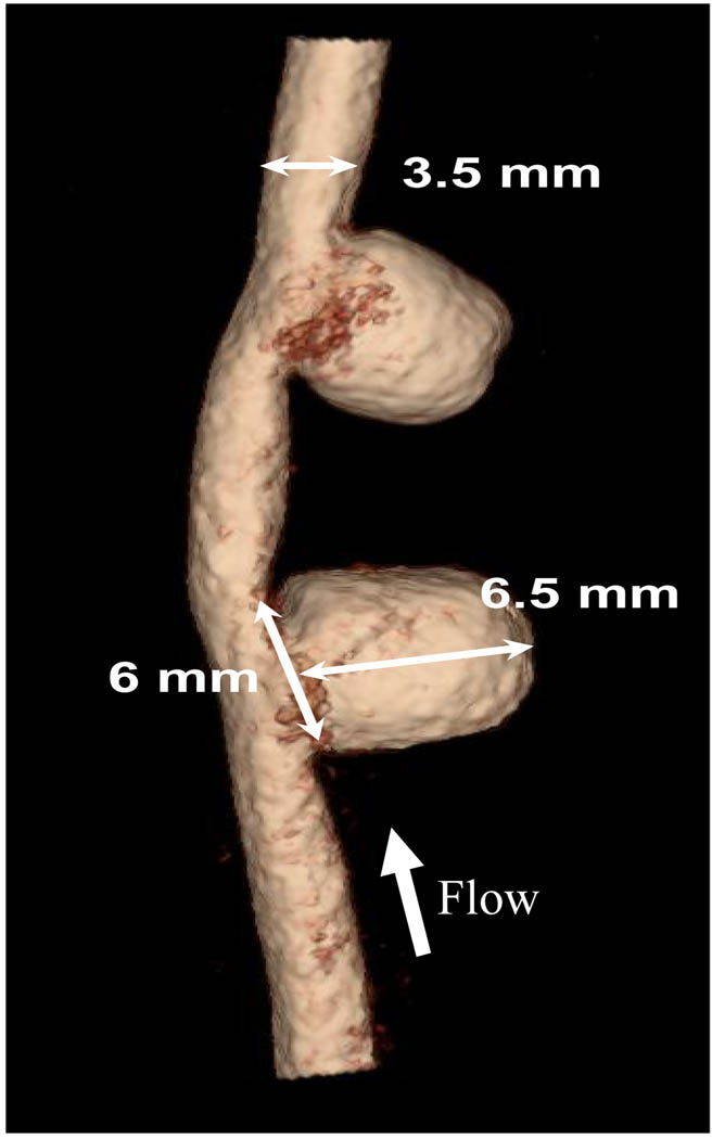
A pair of aneurysms was surgically created in each dog carotid artery22–24 (Figure 1). Flow rate in the parent vessel was recorded using a perivascular ultrasonic flow probe (Model 4PMP, Transonic, Ithaca, NY). Four weeks after the aneurysm creation, aneurysm patency and dimension were examined using digital subtracted angiography (DSA) as well as rotational digital subtracted angiography (R-DSA) with a Toshiba Infinx C-arm (Toshiba Medical Systems Corp., Tustin, CA). Both aneurysms remained patent, and had approximately the same sizes after 4 weeks. We selected the proximal aneurysm in our studies and used the distal aneurysm as a control. Based on the acquired geometry and vessel measurements, we selected the appropriate dimensions of the asymmetric stent such as, size of the asymmetric patch, stent diameter, and stent length.
Figure 1.
Renderings of 3D angiograms of aneurysms created in dog carotid artery.
2.2. Asymmetric Stent Prototype Fabrication
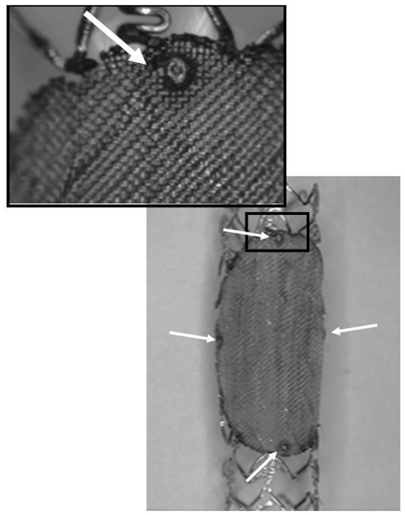
The prototypes of the asymmetric vascular stent (Figure 2) were built by modifying commercial Penta® coronary stents (Guidant Corp., Santa Clara, CA). We attached a low-porosity (porosity = 25%) patch over the structure of the stent using laser micro-welding techniques. A NdYag laser (Equilasers, Santa Clara, CA) which has emissions in the infrared range of the spectrum was used to weld the patch to the stent. The patch had an ellipsoidal form which was similar to the shape of the orifice of the implanted side-wall aneurysms. In order to indicate the position of the asymmetric vascular stent in vivo, we developed a system of markers which unambiguously identified the location and orientation of the stent under x-ray guidance. These markers were made of small platinum dots (100–159 µm diameter) welded onto the stent as shown with the white arrows in Figure 2. In the final phase, the stents were sterilized and crimped back onto a balloon tipped catheter. The final diameter of the crimped stent was between 1.2 and 1.4 mm.
Figure 2.
Asymmetric stent with Pt markers at the edge of the patch.
2.3 Treatment of Aneurysms
The treatment of the aneurysms followed the following standard procedure. We introduced a 7 French sheath to the left femoral artery. The positioning of the stent and the deployment took place under x-ray control using an Infinix VS-I image intensifier c-arm (Toshiba Medical Systems Corp., Tustin, CA). The stent was advanced to the carotid area using a fluoroscopic road map. During fluoroscopy we roughly aligned the stent with respect to the aneurysm neck. For accurate alignment of the patch with aneurysm orifice, we took the angled projection that offered the best view of the aneurysm neck and used low-frame-rate (2 fps) digital angiography to align the patch with the aneurysm orifice. The digital angiography was used to take advantage of the higher image accuracy this modality offers. In the previous work25, we proved that using standard digital angiography, a stent could be placed with an accuracy of better than 12 degrees with regard to the aneurysm neck. After the stent was aligned the balloon was inflated and the stent was deployed.
2.4 Computational Fluid Dynamic Analysis
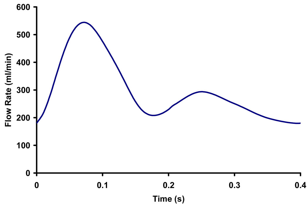
Immediately before stent placement, the aneurysm was imaged using 3D-digital subtraction angiography. The 3D lumens of the parent vessel and aneurysm were reconstructed from rotational angiograms using the angiographic equipment’s standard software and these 3D lumens were used for the subsequent CFD analysis. We used commercial mesh generation software (ICEM-CFD, NY) to generate hybrid meshes consisting of tetrahedral meshes with refined prism meshes near the boundary of the aneurysm model. The Navier-Stoke equations were solved using commercial finite volume software (StarCD®, CD-adapco, NY) with second-order accuracy. Grid independence was achieved with several refinements of grids resulting in approximate 2.1 millions of cells. We assumed laminar, incompressible flow and Newtonian fluid in a rigid wall model. Fluid density of 1060kg/m3 and viscosity of 3.5cP were used in the CFD simulation so as to simulate blood. The recorded pulsatile flow waveform of the carotid artery was represented by a 6-term Fourier series to be used as the inlet condition for the CFD calculation. A mean Reynold’s number (based on parent vessel diameter) of 320 was used in steady state analysis, while a Womersley number of 6.52 was used in the pulsatile flow analysis with the measured waveform (Figure 3).
Figure 3.
Recorded in vivo waveform used in CFD analysis.
Fully resolving the individual filaments of the physical wire mesh patch is computational costly since the filaments are too small in comparison to the computational cell size. Thus, we modeled the asymmetric stent effect by specifying a pressure drop (resistance) across the low porosity region of the stent based on the geometry and orientations of the filaments26. The pressure drop across the porous patch was described by26 (Rep < 50):
| (1) |
where ΔP is the pressure drop (Pa), Rep is the Reynold’s Number based on pore size, U is the velocity (m/s), ρ is the density of fluid (kg/m3) and ε is the stent patch porosity. The porosity of the patch (ε) is defined as the ratio of the open area to the total area of the mesh.
3. RESULTS
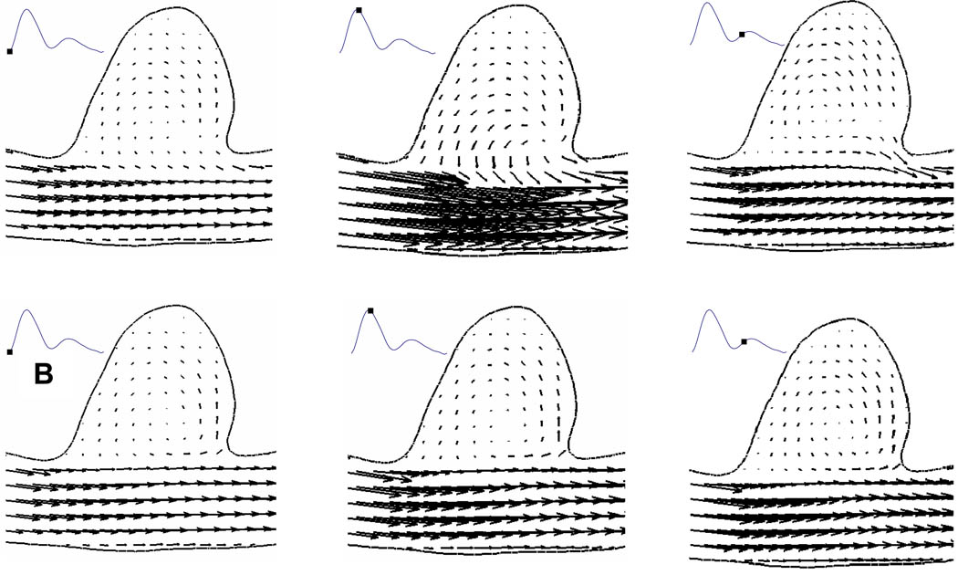
In the untreated case, the flow entered the aneurysm from the distal neck, formed a coherent vortex in the aneurysm cavity and exited from the proximal neck (Figure 4). Similar flow patterns have been quantified by multiple authors9, 14, 16. With a patch placed across the aneurysm neck, we found that the flow entering the aneurysm cavity was significantly less over the cardiac cycle (Figure 4), as compared with untreated aneurysm. In addition, inside the cavity of stented aneurysm, the flow was more stagnant.
Figure 4.
Comparison of velocity vectors at different phases in a cardiac cycle between an (A) untreated aneurysm and (B) aneurysm treated with asymmetric stent from CFD results.
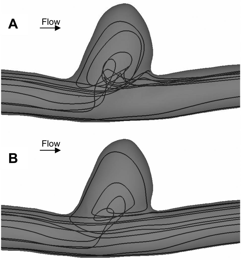
We traced a group of simulated blood particles from the inlet of the computational domain and found that without any treatment, some of the particle paths entered the aneurysm cavity (Figure 5A). With a patch placed across the aneurysm neck, we found that only a small amount of the same group of particles entered the aneurysm cavity and majority of the particles flowed in the parent vessel as indicated by the large change in streamlines depicting particle paths (Figure 5B). In addition, with a patched placed across the aneurysm neck, the flow at the aneurysm neck became more uniform as opposed to the more variable flow pattern in the untreated aneurysm.
Figure 5.
Comparison of instantaneous streamlines at peak systole between an (A) untreated aneurysm and (B) aneurysm treated with asymmetric stent from CFD results. With a patch covering the aneurysm neck (B), the flow became more uniform as compared with untreated aneurysm (A).
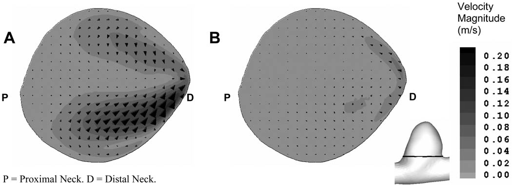
To investigate the flow field generated by asymmetric stents, we compared the in-plane velocity vectors and magnitudes across the orifice of the untreated and stented aneurysm geometries from the CFD results (Figure 6). We found the in-plane velocity magnitude across the aneurysm neck was reduced 3-fold at peak systole in the aneurysm treated with asymmetric stent. In addition, we also found that by placing an asymmetric stent with 25% porosity across the aneurysm neck, the mass inflow to the aneurysm was reduced by 51% at peak systole, as compared with the untreated aneurysm.
Figure 6.
Comparison of in-plane velocity vectors and magnitude in a plane above the aneurysm orifice (see insert figure) at peak systole: (A) untreated aneurysm and (B) aneurysm treated with asymmetric stent.
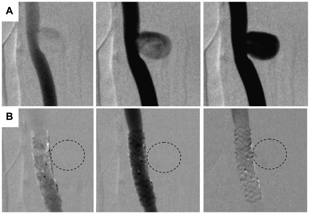
Similar substantial flow reduction was also observed in the digital subtraction angiography image sequences (Figure 7). The image sequences were similar to different phases over a cardiac cycle in CFD analysis. Without any treatment, the contrast flow filled up the entire aneurysm cavity (Figure 7A). Immediately after the placement of asymmetric stent across the aneurysm neck, we observed no detectable amount of contrast media seepage into the aneurysm cavity (Figure 7B). The contrast flow and filling processes as seen in the angiography image sequences in stented aneurysm inferred less flow entered the aneurysm cavity and the flow inside the aneurysm was more stagnant. Both angiography sequences and CFD results were in agreement qualitatively in describing the flow in the untreated and stented aneurysms.
Figure 7.
Comparison of the DSA sequences in untreated aneurysm (A, top row) and aneurysm treated with asymmetric stent where the markers indicate the location of the patch (B, bottom row). (Dotted lines represent the approximate location of aneurysm.)
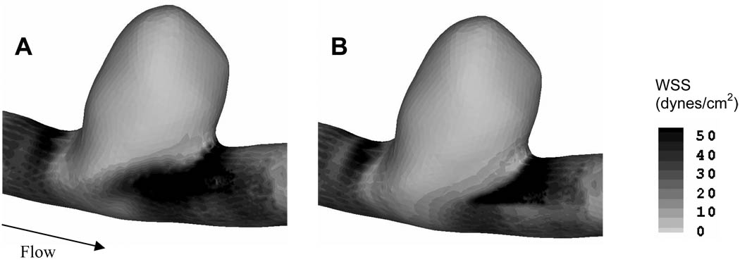
In an attempt to identify the hemodynamic stresses in both untreated and stented aneurysms from CFD analysis, we plotted the wall shear stress (Figure 8). However, both the untreated and stented aneurysm sacs experienced low wall shear stress, possibly due to the sidewall saccular aneurysm geometry.
Figure 8.
Comparison of wall shear stress magnitude between (A) untreated, and (B) stented aneurysms.
After 1 month, the aneurysms were harvested to check for thrombus formation. We observed that the aneurysm treated with the asymmetric stent was fully thrombosed, whereas the control (untreated aneurysm) remained patent (data not shown).
4. DISCUSSION
4.1 Modeling technique
In vitro experiments and numerical simulations have been used to study the flow field in stented aneurysm models to better understand the aneurysmal hemodynamics associated with different types of stents9–17. Previously, in vitro studies have been limited to 2D flow field measurements and scaled-up models that frequently require optical access. For these experiments there were difficulties in reproducing the in vivo geometries and in vivo hemodynamic environments. In the numerical studies, the major challenge in simulating a stented aneurysm is to fully resolve the individual filaments of the physical stent struts. These filaments are usually complex and small in diameters (~80–150 µm) as compared with intracranial artery diameter (3–5 mm) and aneurysm size (1–40 mm). These filaments are even finer for the asymmetric stent’s patch (~25µm). Consequently, the number of computational cells and costs can increase drastically. In addition, to compensate for the computational costs and, due to the complexity of stent designs, most numerical studies focused on a stent placed in an idealized aneurysm geometry9, 14. In addition, flow modification in a stented aneurysm is influenced by different stent parameters such as porosity or stent strut dimensions16. Different sets of computational mesh are needed for each particular type of stent design. Therefore, such direct stent simulations make exploration of different stent designs difficult. To overcome these challenges, we modeled the asymmetric stent effect by specifying a pressure drop (resistance) across the low porosity region of the stent based on the geometry of the filaments26. This is the first attempt to study the flow modification in such low porosity types of stent by using a pressure drop model in an in vivo aneurysm model. Our method in applying the pressure drop across the patch provides a new technique in exploring different stent designs. Additionally, this type of modeling technique only incorporates simple computational meshes, which significantly reduces the computational costs.
Since the description of pressure drop over the asymmetric stent depended on different parameters, including, strut orientation, strut diameter, porosity, etc., experimental validation of the relationship between the pressure drop and individual stent design is necessary. For the particular patch that we used in this study, we found that the maximum differences between the pressure drop from equation (1) and the pressure drop from experimental measurement of the actual patch was approximately 10%27. Further investigation to obtain the relationship between the pressure drop and the associated patch design is necessary to better describe the stented aneurysmal flow dynamics.
4.2 Endovascular treatments
Since the introduction of GDC coils in the early 1990s, coils have gained popularity in aneurysm treatment. However, wide neck or giant aneurysms are difficult to treat with coils alone due to coil compaction or herniation, aneurysm regrowth and recanalization7, 28–30. In addition, dense coil packing does not always guarantee permanent occlusion31 and patients with intracranial aneurysms may have neurological deterioration after coil embolization7, 30, 32. Geremia et al.33 and Wakhloo et al.5 have demonstrated complete occlusion of sidewall and fusiform aneurysms on the carotid arteries of dogs by using stents alone. However, in vitro experiments showed that the performance of a stent in reducing the flow activity in the aneurysm sac highly depends on the aneurysm geometry34. A stent alone may not provide reliable treatment for an aneurysm due to the strong impingement flow35.
Ideally, intracranial stents should exclude the aneurysm from the circulation by reducing the aneurysmal inflow and protecting the aneurysm from strong impinging flow. It should also leave the adjacent perforators open to prevent adverse outcome. Our approach of covering the aneurysm neck with a low porosity patch, while maintaining the perforators open to the porous part of the stent has the required characteristics. The approach of using an asymmetric stent has achieved initial promising results in in vitro experiments19, 21. In this in vivo experiment, immediately after the placement of asymmetric stent across the aneurysm neck, we observed no detectable amounts of contrast media seeping into the aneurysm cavity, which implied that the flow inside the aneurysm cavity was rather stagnant. Such stagnant flow condition may be pro-thombogenic. Upon aneurysm harvest, we found that the aneurysm treated with asymmetric stent was fully thrombosed, whereas the untreated control remained patent. Therefore, by altered the flow entered the aneurysm cavity through asymmetric stent; it would be able to create an environment to promote thrombosis. The current in vivo experiment has further proven the feasibility of the asymmetric stent in treating intracranial aneurysms. In addition, treating the aneurysm with an asymmetric stent alone significantly reduces the amount of foreign objects in the artery, as compared with coils. Furthermore, the low porosity patch also protects the aneurysm wall from strong impingement flow and elevated wall shear stress, which are believed to contribute to aneurysm dilation36, 37. With the aid of advanced angiography image systems and a less complication interventional procedure employing asymmetric stents may provide new options for aneurysm treatment.
4.3 Future Considerations
While most of the aneurysms are found in bifurcations and on the outer wall of a curved parent vessel, the sidewall saccular aneurysm on a straight vessel in this in vivo experiment is rarely found in human intracranial aneurysm cases. In close examination of the aneurysm geometry, we found that the aneurysm was located on the inner wall of a parent vessel with a very small curvature, mimicking a straight parent vessel. The flow entered this type of aneurysm geometry has low momentum and predominantly is driven by viscous-shear force35. Consequently, due to this type of aneurysm geometry, there is no significant difference in the hemodynamic stresses in both untreated and stented aneurysms. Nevertheless, the asymmetric stent successfully altered the hemodynamic environment to induce stable aneurysmal thrombus.
On the other hand, the ability of a stent to reduce the flow into the aneurysm is also related to parent vessel and aneurysm geometry34. Similar studies are necessary to investigate the flow patterns in different types of aneurysm geometries, such as an aneurysm located on a bifurcation or curved parent vessel. The evaluation of an asymmetric stent deployed in an aneurysm located on a curved parent vessel is under investigation.
Although the current computer modeling technique only explores the simulation of the porosity of asymmetric stents used in the in vivo experiment, it should be easy to extend this modeling technique to different stent designs. The pressure drop across the low porosity patch is dependent on several parameters, including strut orientation, pore size, porosity, etc. It is thus necessary to determine the appropriate pressure drop description and associate it with the specific stent design. In addition, experimental validation should be conducted to verify the relationship between the pressure drop and the particular stent design27. While we have demonstrated progress in developing asymmetric stents, it still remains unclear what optimum porosity for the patch is needed to achieve thrombosis. Further investigation over larger number of experiments is needed to better characterize the role of asymmetric stents and consequent thrombus formation.
5. CONCLUSION
This is the first attempt at studying flow modification using an in vivo aneurysm model with low porosity patch across the aneurysm neck. We created vein-pouch aneurysms on the carotid artery of a canine and deployed an asymmetric stent, with a patch of 25% porosity across the aneurysm neck and 80% porosity elsewhere, to modify the aneurysmal flow. To evaluate the effect of the stent on hemodynamics, CFD calculations incorporating stent modeling were employed. We modeled the patch by specifying a pressure drop across the low porosity region of the stent. From the CFD results, we found that the asymmetric stent reduced the inflow into the aneurysm by 51% and created increased stasis in the aneurysm. DSA sequences also showed substantial flow reduction into the stented aneurysm immediately after stent deployment. Both angiography sequences and CFD results were in agreement qualitatively in describing the flow in the untreated and stented aneurysms. We can conclude that asymmetric stents may be a viable image guided intervention for treating intracranial aneurysms with the desired flow modification features.
ACKNOWLEDGEMENT
We gratefully acknowledge J. Yamamoto, M.D., Ann Marie Paciorek for surgical guidance and A. Mulay for inspiration in this work. This material is based upon work supported in part by National Institute of Health under Grants EB002873, NS43024 and EB02916, National Science Foundation under Grant BES-0302389 and an equipment grant from Toshiba Medical Systems Corp.
REFERENCES
- 1.Molyneux A, Kerr R, Stratton I, Sandercock P, Clarke M, Shrimpton J, Holman R. International Subarachnoid Aneurysm Trial (ISAT) of neurosurgical clipping versus endovascular coiling in 2143 patients with ruptured intracranial aneurysms: a randomised trial. Lancet. 2002;360(9342):1267–1274. doi: 10.1016/s0140-6736(02)11314-6. [DOI] [PubMed] [Google Scholar]
- 2.Horowitz MB, Purdy PD. The use of stents in the management of neurovascular disease: a review of historical and present status. Neurosurgery. 2000;46(6):1335–1342. doi: 10.1097/00006123-200006000-00010. discussion 1342-3. [DOI] [PubMed] [Google Scholar]
- 3.Han PP, Albuquerque FC, Ponce FA, MacKay CI, Zabramski JM, Spetzler RF, McDougall CG. Percutaneous intracranial stent placement for aneurysms. J Neurosurg. 2003;99(1):23–30. doi: 10.3171/jns.2003.99.1.0023. [DOI] [PubMed] [Google Scholar]
- 4.Krings T, Hans FJ, Moller-Hartmann W, Brunn A, Thiex R, Schmitz-Rode T, Verken P, Scherer K, Dreeskamp H, Stein KP, Gilsbach J, Thron A. Treatment of experimentally induced aneurysms with stents. Neurosurgery. 2005;56(6):1347–1359. doi: 10.1227/01.neu.0000159887.03290.d1. discussion 1360. [DOI] [PubMed] [Google Scholar]
- 5.Wakhloo AK, Lanzino G, Lieber BB, Hopkins LN. Stents for intracranial aneurysms: the beginning of a new endovascular era? Neurosurgery. 1998;43(2):377–379. doi: 10.1097/00006123-199808000-00126. [DOI] [PubMed] [Google Scholar]
- 6.Yang C-YJ, Rudin S, Wang Z, Wu Y. Determination of the probability for blocking small side-branch perforator vessels during cerebrovascular stent deployment. Science Program and 87th Scientific Assembly and Annual Meeting of RSNA; Chicago. 2001. p. 159. [Google Scholar]
- 7.Malisch TW, Guglielmi G, Vinuela F, Duckwiler G, Gobin YP, Martin NA, Frazee JG. Intracranial aneurysms treated with the Guglielmi detachable coil: midterm clinical results in a consecutive series of 100 patients. J Neurosurg. 1997;87(2):176–183. doi: 10.3171/jns.1997.87.2.0176. [DOI] [PubMed] [Google Scholar]
- 8.Heilman CB, Kwan ES, Wu JK. Aneurysm recurrence following endovascular balloon occlusion. J Neurosurg. 1992;77(2):260–264. doi: 10.3171/jns.1992.77.2.0260. [DOI] [PubMed] [Google Scholar]
- 9.Aenis M, Stancampiano AP, Wakhloo AK, Lieber BB. Modeling of flow in a straight stented and nonstented side wall aneurysm model. J Biomech Eng. 1997;119(2):206–212. doi: 10.1115/1.2796081. [DOI] [PubMed] [Google Scholar]
- 10.Imbesi SG, Kerber CW. Analysis of slipstream flow in a wide-necked basilar artery aneurysm: evaluation of potential treatment regimens. AJNR Am J Neuroradiol. 2001;22(4):721–724. [PMC free article] [PubMed] [Google Scholar]
- 11.Liou TM, Liou SN. Pulsatile flows in a lateral aneurysm anchored on a stented and curved parent vessel. Exp. Mech. 2004;44(3):253–260. [Google Scholar]
- 12.Liou TM, Liou SN, Chu KL. Intra-aneurysmal flow with helix and mesh stent placement across sidewall aneurysm pore of a straight parent vessel. J Biomech Eng. 2004;126(1):36–43. doi: 10.1115/1.1644566. [DOI] [PubMed] [Google Scholar]
- 13.Rhee K, Han MH, Cha SH. Changes of flow characteristics by stenting in aneurysm models: influence of aneurysm geometry and stent porosity. Ann Biomed Eng. 2002;30(7):894–904. doi: 10.1114/1.1500406. [DOI] [PubMed] [Google Scholar]
- 14.Stuhne GR, Steinman DA. Finite-element modeling of the hemodynamics of stented aneurysms. J Biomech Eng. 2004;126(3):382–387. doi: 10.1115/1.1762900. [DOI] [PubMed] [Google Scholar]
- 15.Yu SC, Zhao JB. A steady flow analysis on the stented and non-stented sidewall aneurysm models. Med Eng Phys. 1999;21(3):133–141. doi: 10.1016/s1350-4533(99)00037-5. [DOI] [PubMed] [Google Scholar]
- 16.Lieber BB, Livescu V, Hopkins LN, Wakhloo AK. Particle image velocimetry assessment of stent design influence on intra-aneurysmal flow. Ann Biomed Eng. 2002;30(6):768–777. doi: 10.1114/1.1495867. [DOI] [PubMed] [Google Scholar]
- 17.Canton G, Levy DI, Lasheras JC, Nelson PK. Flow changes caused by the sequential placement of stents across the neck of sidewall cerebral aneurysms. J Neurosurg. 2005;103(5):891–902. doi: 10.3171/jns.2005.103.5.0891. [DOI] [PubMed] [Google Scholar]
- 18.Ionita C, Mulay A, Rudin S, Meng H. Particle image velocimetry (PIV) evaluation of flow modification in aneurysm phantoms using asymmetric stents. SPIE; Proceedings from Medical Imaging 2004: Physiology, Function, and Structure from Medical Images; San Diego, CA. 2004. pp. 295–306. paper #36. [DOI] [PMC free article] [PubMed] [Google Scholar]
- 19.Rudin S, Wang Z, Kyprianou I, Hoffmann KR, Wu Y, Meng H, Guterman LR, Nemes B, Bednarek DR, Dmochowski J, Hopkins LN. Measurement of flow modification in phantom aneurysm model: comparison of coils and a longitudinally and axially asymmetric stent--initial findings. Radiology. 2004;231(1):272–276. doi: 10.1148/radiol.2311021741. [DOI] [PubMed] [Google Scholar]
- 20.Wang ZJ, Hoffmann KR, Wang Z, Rudin S, Guterman LR, Meng H. Contrast settling in cerebral aneurysm angiography. Phys Med Biol. 2005;50(13):3171–3181. doi: 10.1088/0031-9155/50/13/014. [DOI] [PubMed] [Google Scholar]
- 21.Wang Z, Ionita C, Rudin S, Hoffmann K, Paxton A, Bednarek D. Angiographic analysis of blood flow modification in cerebral aneurysm models with a new asymmetric stent. SPIE; Proceedings from Medical Imaging: Physiology, Function, and Structure from Medical Images; San Diego, CA. 2004. pp. 307–318. paper #37. [DOI] [PMC free article] [PubMed] [Google Scholar]
- 22.German WJ, Black SP. Experimental production of carotid aneurysms. N Engl J Med. 1954;250(3):104–106. doi: 10.1056/NEJM195401212500303. [DOI] [PubMed] [Google Scholar]
- 23.Kerber CW, Buschman RW. Experimental carotid aneurysms: I. Simple surgical production and radiographic evaluation. Invest Radiol. 1977;12(2):154–157. doi: 10.1097/00004424-197703000-00009. [DOI] [PubMed] [Google Scholar]
- 24.Massoud TF, Guglielmi G, Ji C, Vinuela F, Duckwiler GR. Experimental saccular aneurysms. I. Review of surgically-constructed models and their laboratory applications. Neuroradiology. 1994;36(7):537–546. doi: 10.1007/BF00593517. [DOI] [PubMed] [Google Scholar]
- 25.Ionita C, Rudin S, Bednarek D, Hoffmann K. Microangiographic image guided localization of a new asymmetric stent for treatment of cerebral aneurysms. SPIE; Proceedings from Medical Imaging 2005: Visualization, Image-Guided Procedures, and Display; San Diego, CA. 2005. pp. 354–365. paper #40. [DOI] [PMC free article] [PubMed] [Google Scholar]
- 26.Idelchik IE, Steinberg MO. Handbook of hydraulic resistance. 3rd ed. Boca Raton, FL: CRC Press; 1994. p. 790. [Google Scholar]
- 27.Ionita C. Design, X-ray image guidance and flow characterization of new asymmetric vascular stents, in Department of Physics. SUNY: Buffalo: University at Buffalo; 2005. [Google Scholar]
- 28.Gobin YP, Vinuela F, Gurian JH, Guglielmi G, Duckwiler GR, Massoud TF, Martin NA. Treatment of large and giant fusiform intracranial aneurysms with Guglielmi detachable coils. J Neurosurg. 1996;84(1):55–62. doi: 10.3171/jns.1996.84.1.0055. [DOI] [PubMed] [Google Scholar]
- 29.Mericle RA, Wakhloo AK, Lopes DK, Lanzino G, Guterman LR, Hopkins LN. Delayed aneurysm regrowth and recanalization after Guglielmi detachable coil treatment. Case report. J Neurosurg. 1998;89(1):142–145. doi: 10.3171/jns.1998.89.1.0142. [DOI] [PubMed] [Google Scholar]
- 30.Gruber A, Killer M, Bavinzski G, Richling B. Clinical and angiographic results of endosaccular coiling treatment of giant and very large intracranial aneurysms: a 7-year, single-center experience. Neurosurgery. 1999;45(4):793–803. doi: 10.1097/00006123-199910000-00013. discussion 803-4. [DOI] [PubMed] [Google Scholar]
- 31.Reul J, Spetzger U, Weis J, Sure U, Gilsbach JM, Thron A. Endovascular occlusion of experimental aneurysms with detachable coils: influence of packing density and perioperative anticoagulation. Neurosurgery. 1997;41(5):1160–1165. doi: 10.1097/00006123-199711000-00028. discussion 1165-8. [DOI] [PubMed] [Google Scholar]
- 32.Russell SM, Nelson PK, Jafar JJ. Neurological deterioration after coil embolization of a giant basilar apex aneurysm with resolution following parent artery clip ligation. Case report and review of the literature. J Neurosurg. 2002;97(3):705–708. doi: 10.3171/jns.2002.97.3.0705. [DOI] [PubMed] [Google Scholar]
- 33.Geremia G, Haklin M, Brennecke L. Embolization of experimentally created aneurysms with intravascular stent devices. AJNR Am J Neuroradiol. 1994;15(7):1223–1231. [PMC free article] [PubMed] [Google Scholar]
- 34.Wang Z, Meng H, Woodward S, Hoi Y, Rudin S, Guterman LR, Hopkins LN. Importance of Parent Vessel Geometry for Aneurysm Stenting. 2003 CNS Abstract Program: The Essence of Neurological Surgery; 53rd Congress of Neurological Surgeons Annual Meeting ; Denver, CO. 2003. pp. Abstract No. 169. [Google Scholar]
- 35.Hoi Y, Meng H, Woodward SH, Bendok BR, Hanel RA, Guterman LR, Hopkins LN. Effects of arterial geometry on aneurysm growth: three-dimensional computational fluid dynamics study. J Neurosurg. 2004;101(4):676–681. doi: 10.3171/jns.2004.101.4.0676. [DOI] [PubMed] [Google Scholar]
- 36.Sekhar LN, Heros RC. Origin, growth, and rupture of saccular aneurysms: a review. Neurosurgery. 1981;8(2):248–260. doi: 10.1227/00006123-198102000-00020. [DOI] [PubMed] [Google Scholar]
- 37.Ferguson GG. Physical factors in the initiation, growth, and rupture of human intracranial saccular aneurysms. J Neurosurg. 1972;37(6):666–677. doi: 10.3171/jns.1972.37.6.0666. [DOI] [PubMed] [Google Scholar]


