Abstract
We developed a straightforward, fast, and versatile technique to fabricate mineralized nanofibrous polymer scaffolds for bone regeneration in this work. Nanofibrous poly(l-lactic acid) scaffolds were fabricated using both electrospinning and phase separation techniques. An electrodeposition process was designed to deposit calcium phosphate on the nanofibrous scaffolds. Such scaffolds contain a high quality mineral coating on the fiber surface with tunable surface topography and chemical composition by varying the processing parameters, which can mimic the composition and structure of natural bone extracellular matrix and provide a more biocompatible interface for bone regeneration.
Keywords: Mineralization, Medical Application, Tissue Engineering, Fiber, Nanostructure, Eletrospinning, Electrodeposition
Introduction
The development of biomaterials capable of mimicking the structure and function of natural extracellular matrix (ECM) is a rapidly growing research area.[1–3] Natural bone is mainly composed of collagen fibers and hydroxyapatite (HA) nanocrystals. Therefore, nano-fibrous composites comprising bioabsorbable polymers and calcium phosphate ceramics may be particularly suitable for bone tissue regeneration because of their capacity to provide a good balance of biocompatibility, biodegradability and mechanical performance.[4, 5] To date, three major processing techniques have been utilized to fabricate single-component or polymer-ceramic composite nanofibrous scaffolds for bone tissue regeneration. These include electrospinning,[6–8] phase separation,[1–3] and self-assembly.[9] Composite nanofibrous scaffolds fabricated using these techniques have led to enhanced osteoblastic differentiation in vitro and improved bone formation in vivo versus single-component nanofibrous scaffolds, thus rendering them promising scaffolds for bone regeneration.
Nanofibers are good tissue engineering scaffolds because of their unique properties such as high surface-to-volume ratio, high porosity and morphological similarity to the natural ECM.[1, 7, 8, 10] Electrospinning has raised substantial interest as a simple and versatile technique to produce ultrafine fibers with diameters ranging from microns down to a few nanometers.[8, 11] To establish an ideal scaffold for bone regeneration, considerable efforts have been made to create porous fibrous matrices using phase separation[12] and electrospinning techniques,[13–16] focusing on the development of ceramic/polymer fibrous composites or hybrids that can overcome the limitations of each single component. The most common approach for fabricating ceramic/polymer fibrous composites is in-situ electrospinning of the ceramic and polymer mixture solution. This has led to a number of ceramic-filled polymeric fibrous structures, but has also led to uneven distribution of ceramic particles within the polymeric matrix and the content of ceramic component was limited.[13, 14] Biomimetic mineralization is an alternative method for the production of ceramic/polymer composite materials, in which partially carbonated hydroxyapatite grows onto a polymer scaffold when incubated in a simulated body fluid (SBF).[12, 15, 17–19] However, this is a time-consuming process, taking several weeks to form ideal mineralized layers,[15] and leading to the biodegradation of polymer materials prior to their use in the tissue engineering application. Additionally, this process could lead to the undesired release of any encapsulated therapeutic agents or growth factors. Recent attempts have been made to accelerate the biomimetic mineralization process of electrospun nanofibers in which charged polyelectrolyte multilayers were generated on the surface of pristine polymer fibers through layer-by-layer (LBL) self assembly. The introduction of charged bioactive polymers on the surface of electrospun fibers via LBL technique not only provided favorable cytocompatibility but also facilitated more rapid mineralization.[20] An electrodeposition technique has been extensively utilized to deposit apatite on metallic substrates (e.g., stainless steel, titanium and their alloys) with the purpose of enhancing their bioactivity and biocompatibility, and has proven to be a fast and effective method to fabricate apatite coatings on metallic substrates.[21–25] However, the high temperature process or/and alkaline solution involved in electrodepositing minerals on metallic materials is not suitable for coating apatite onto polymeric materials.
In this work, we present a facile electrodeposition approach to rapidly generate mineralized calcium phosphate coating on the surface of nanofibrous polymer scaffolds fabricated either by electrospinning or by phase separation, focusing primarily on the electrospun poly(L-lactic acid) (PLLA) nanofibers. With this approach, PLLA nanofibrous templates were deposited on the surface of the metallic electrodes, followed by electrodeposition to achieve a stable calcium phosphate coating. Our results show that the approach described herein offers significant advantages over the conventional SBF mineralization of nano-fibrous scaffolds in that a high quality mineral coating can be achieved within one hour by precisely controlling the electrochemical process parameters, and the surface topography of the deposits can be tailored to meet the requirements for cell growth and bone regeneration. Therefore, the hybrid fibrous scaffold prepared by this technique has the potential to mimic both the composition and the structure of natural bone ECM and provide a more biocompatible interface for bone regeneration.
Results and Discussion
We selected PLLA nanofibers as a model polymeric template to demonstrate this methodology because it is one of the most common biodegradable materials and has been extensively used as a bone graft substitute and scaffold for bone tissue engineering.[14, 15, 26, 27] To investigate the effect of fiber diameter on the mineralization rate during electrodeposition, PLLA nanofiber meshes with 4 different fiber diameters were fabricated by electrospinning PLLA solution at 4 different concentrations (6 wt%, 8 wt%, 10 wt% and 12 wt%, respectively). A stainless steel (SS) electrode (20mm × 20mm × 0.2mm) was used as the ground collector to collect nanofibers on both sides. In our study, the nanofibers were collected to achieve a layer thickness of around 200–300 µm. The average fiber diameters were determined from over 50 random measurements on a typical Scanning Electron Microscope (SEM) image (Supporting Information, Figure S1) using ImageJ software (National Institutes of Health, USA), and were found to be 211±71 nm, 482±251 nm, 914±481 nm, and 1363±440 nm when PLLA solution concentration was changed from 6 wt%, 8 wt%, 10 wt%, to 12 wt%. All the fiber-covered electrodes were immersed into alcohol for 1–2 minute prior to electrodeposition, to reduce the hydrogen gas evolution at the deposition electrode.[28]
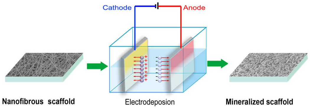
A schematic representation of the fabrication process of mineralized nanofibers is illustrated in Figure 1. Electrodeposition was carried out in a two-electrode electrochemical system under potentiostatic conditions, with the fiber-covered electrode used as the working electrode, and a platinum plate of the same size serving as the counter electrode. The electrolyte was a mixture containing calcium and phosphate ions with Ca/P ratios of 1.67 (corresponding to HA), and the pH value of the electrolyte was adjusted to 4.70. During The deposition parameters such as solution temperature, deposition voltage and deposition time were varied in order to determine their effect on the chemical composition and topography of deposits as well as the deposition rate. For these studies, electrodeposition was conducted using a SS electrode covered with 10% PLLA fibers (prepared using 10 wt% PLLA solution) as the working electrode, unless otherwise noted.
Figure 1.
A schematic representation of the fabrication setup for the mineralization of nanofibrous scaffolds by electrodeposition in a two-electrode system. The electrospun nanofibers were collected on the both sides of cathode.
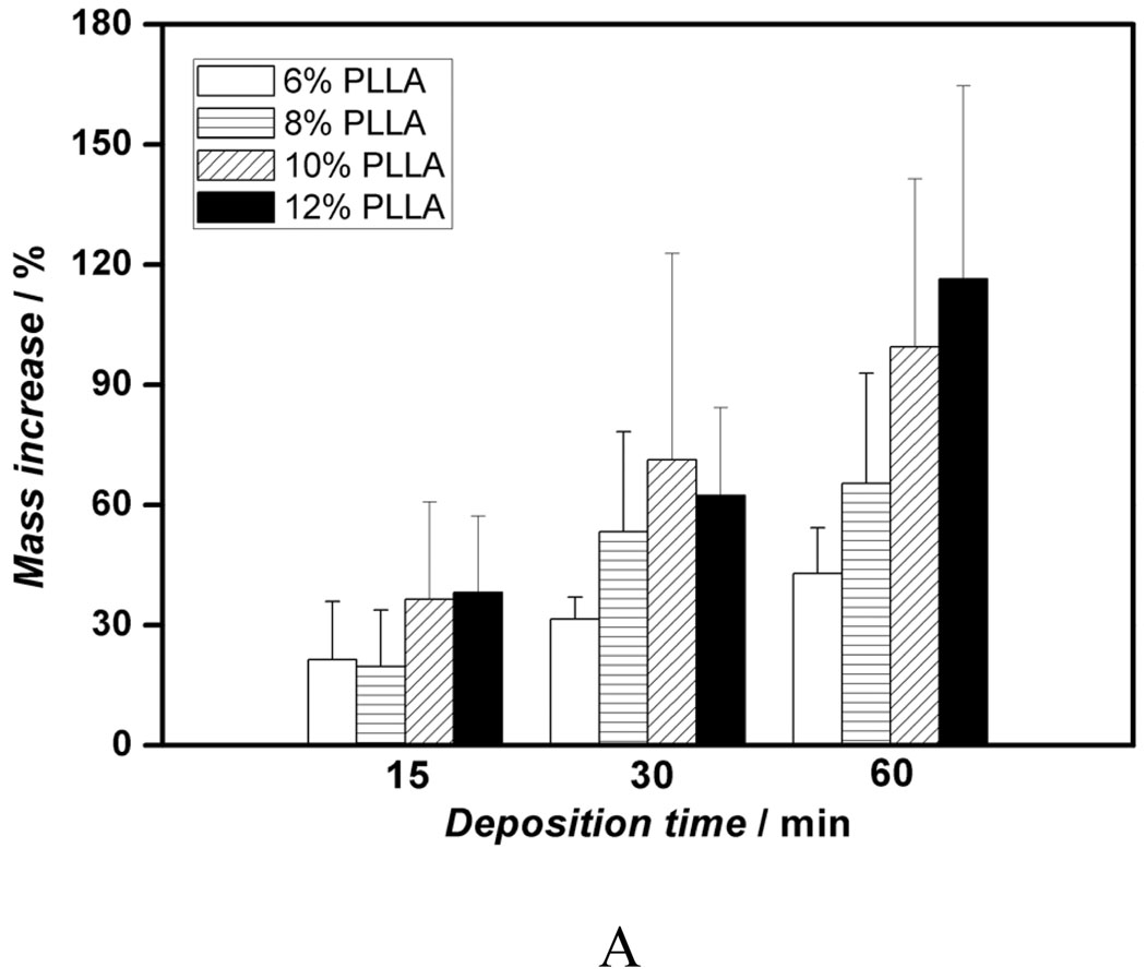
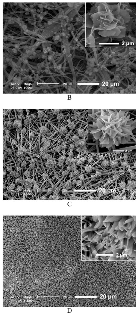
We first investigated the influence of various fiber diameters on the properties of the deposits and electrodeposition rate and found that there was no significant effect of fiber diameter on the chemical composition and topography of deposits under the same deposition parameters. However, the change in fiber diameter had a significant effect on the deposition rate. Figure 2A shows the mass increases of scaffolds produced from different PLLA concentrations (i.e., with different diameters) versus deposition time under 3V and at 60 °C. For a fixed deposition time, an increase in fiber diameter results in an increase in deposition rate. For example, the mass increase for 12wt% PLLA scaffolds with an average fiber diameter of 1363 nm was about 116% after 60 min, whereas deposition for 6wt% scaffold with an average fiber diameter of 211 nm was only about 43%. Figure 2B–D shows the morphological evolution of the calcium phosphate deposited on the surface of nanofibrous scaffolds at 3V and 60°C for different times. As shown in Figure 2B, the sparse flower-like structures composed of fine lamellae emerged on porous nanofibers in the first 15 min, and the inset image indicates that the individual flower has a diameter of about 4 µm. When the deposition time was increased to 30 min, more and more flower-like structures were formed with a larger diameter of about 8 µm, as shown in Figure 2C. With a further increase of deposition time to 60 min, the dense lamellar structures aligned randomly to the surface were formed due to the continuous growth of these flower-like structures; these lamellar structures run into each other and finally create a dense flake-like network, as shown in Figure 2D. Previous studies indicated that the surface topography and roughness of calcium phosphate have significant effects on human bone cells, especially on their proliferation and differentiation.[29, 30] In this study, we have shown how the surface topography of calcium phosphate can be tailored to potentially meet the needs of optimal bone regeneration.
Figure 2.
Mass increase and morphological change of electrospun nanofibrous PLLA scaffolds with eletrodeposition time. A) Mass increase of PLLA nanofibrous scaffolds electrospun with different polymer concentrations (6, 8, 10, and 12%) during the eletrodeposition at 60°C, 3V for 15, 30, and 60 min (SS electrode, n=3). B–D) SEM micrographs of PLLA scaffolds (prepared from 10 wt% PLLA solution) deposited at 60°C, 3V for 15 min (B), 30 min (C), and 60 min (D).
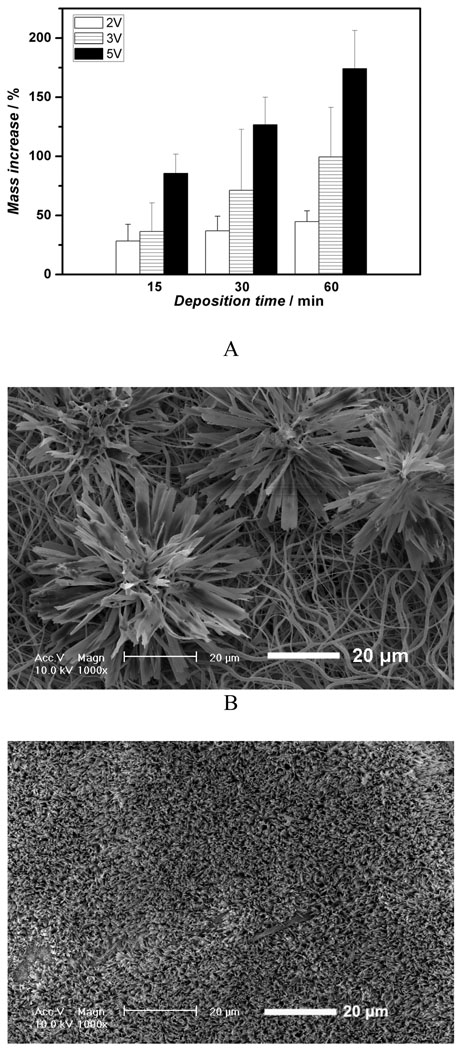
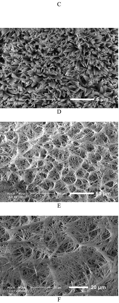
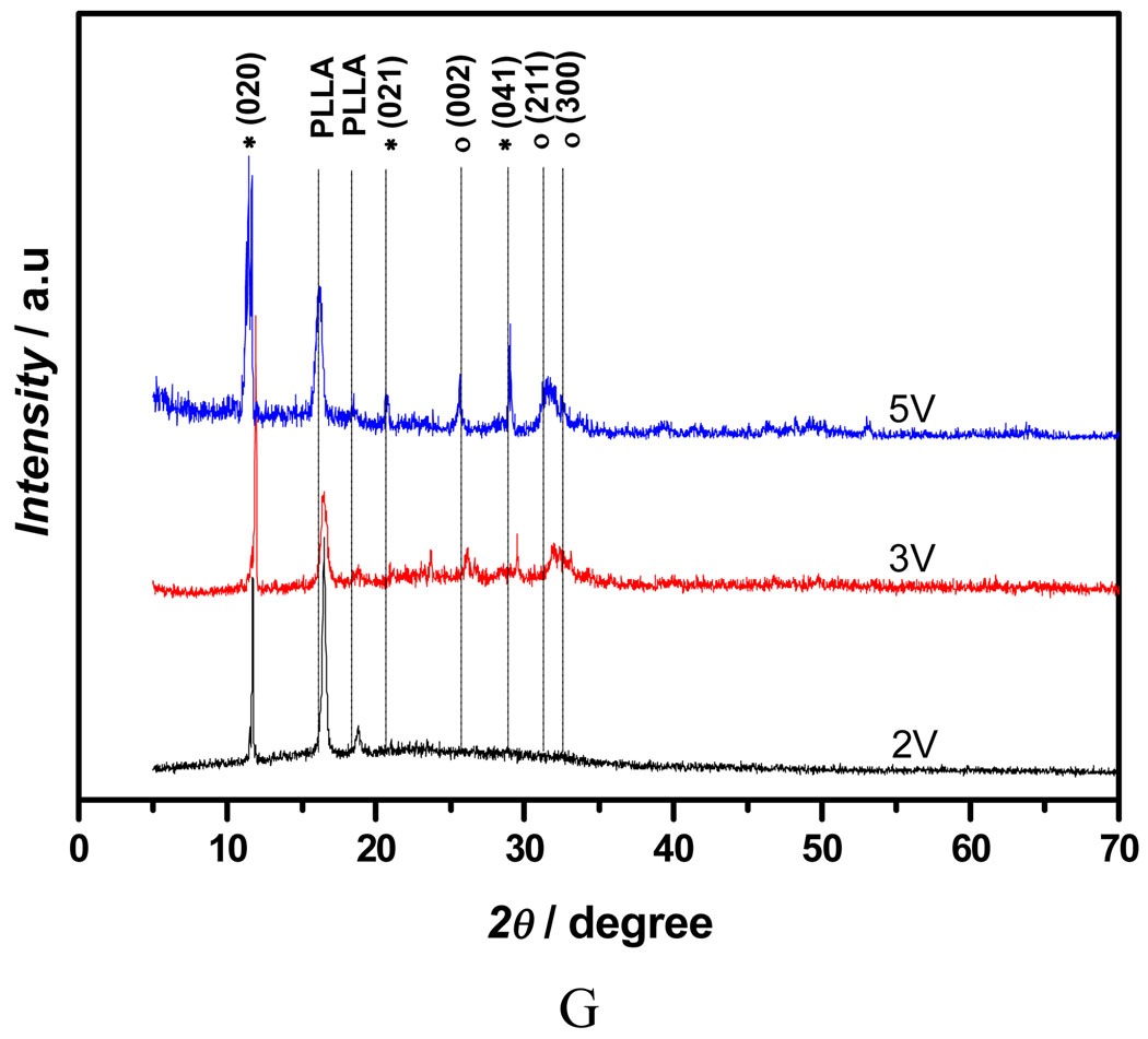
Figure 3A shows the mass increase of the nanofibrous scaffolds versus deposition duration under different deposition voltages. Since all the scaffolds were collected over the same durations, it can be deduced that the amount of calcium phosphate deposition increased with an increase in deposition time or voltage. The mass increase of the scaffold at 5V for 60 min was about 174%, whereas the mass increase of the scaffold deposited at 2V for 15 min was only about 44%. Furthermore, deposition potential was found to be a key factor influencing the topography of the deposits. Figure 3B–E shows the SEM micrographs of the calcium phosphate coating deposited under different voltage for 60 min at 60°C. The topography of coatings changed significantly with varying deposition potentials. A low deposition potential (2V) resulted in a sparse but well-spread flower-like topography (Figure 3B); a moderate deposition potential (3V) led to a uniform and flake-like structure (Figure 3C&D); while higher potential (5V) favored a highly porous fiber-like coating (Figure 3E&F). The X-ray diffraction (XRD) patterns (Figure 3G) show that the deposited crystals were partially converted from dicalcium phosphate dihydrate (DCPD) to HA when the applied voltage was increased from 2V to 5V. In the case of low deposition potential (2V), the peak of calcium phosphate was weak since the deposits were sparse, but the pattern clearly showed the DCPD peak (020) at 2θ=11.7°, which was in the JCPDS card (Joint Committee on Powder Diffraction Standards, card number 09-0077). When the voltage was increased to 3V, the XRD pattern showed that DCPD was still the major phase, but some diffraction peaks corresponding to HA phase were detected (JCPDS card number 09-0432). Further increase of the deposition voltage to 5V resulted in an increase in the HA content, the diffraction peaks corresponding to HA and DCPD phases were both observed in Figure 3G (upper spectrum).
Figure 3.
Mass increase and morphological change of electrospun 10% PLLA nanofibrous scaffolds (prepared from 10 wt% PLLA solution) with different eletrodeposition voltages. A) Mass increase of the scaffolds deposited under different deposition voltages (2V, 3V, 5V) at 60°C for 15, 30, and 60 min (SS electrode, n=3); B–F) SEM micrographs of calcium phosphate coating electrodeposited on PLLA scaffolds for 60 min at 60°C under different voltages: 2V (B), 3V (C&D), 5V (E&F); G) XRD patterns taken from PLLA nanofibrous scaffolds (prepared from 10% PLLA solution) after calcium phosphate deposition for 60 min (60°C) under different voltages (2V, 3V, 5V; * --DCPD, o-- HA).
DCPD is known as a nucleation precursor and can transform into more thermodynamically stable HA, and several methods have been developed to do this, including hydrothermal treatment,[31, 32] sintering,[33] and alkaline treatment.[15, 34, 35] However, due to higher processing temperature (over 100°C) and an alkaline environment which may cause severe damage to the polymer materials,[15] these treatments are not suitable for polymer scaffolds. We demonstrated that a relatively pure HA coating could be achieved at a moderate electrolyte temperature and a moderate deposition voltage in the present study.
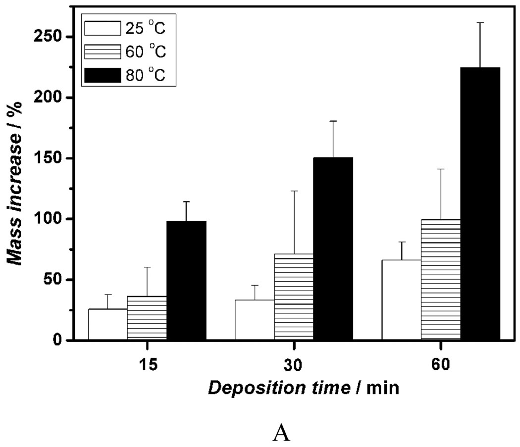
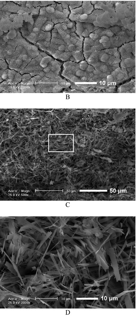
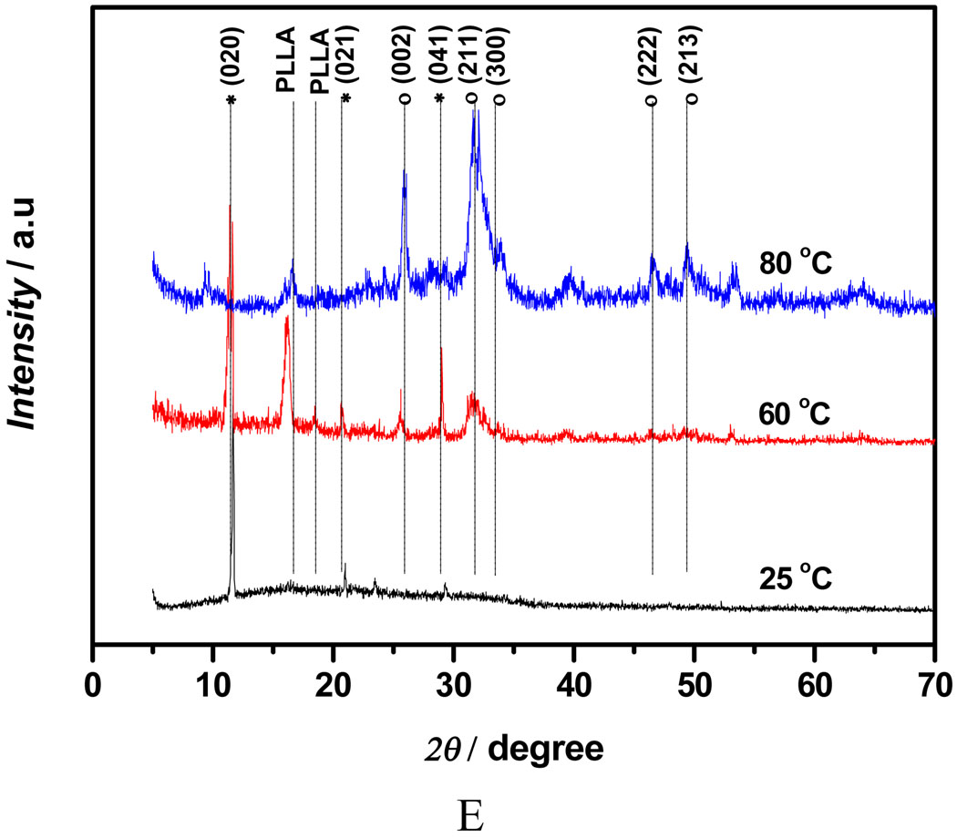
Figure 4A shows the mass increase for 10% PLLA nanofibrous scaffolds undergoing deposition at different temperatures (25°C, 60°C, 80°C) under 3V for 15, 30 and 60 min. The amount of calcium phosphate deposition was increased when the temperature was increased, and the positive effect of electrolyte temperature on deposition rate became more significant with prolonged duration. The scaffold mass was increased to 224% after deposition at 80°C for 60 min, which was significantly higher than that of scaffolds treated at 30 min under the same deposition parameters. The coating obtained at 25°C had an amorphous nest-like structure (Figure 4B), which is similar to what was reported in the previous studies using SBF mineralization of eletrospun PLLA nanofibers.[15, 36] However, the mineral deposited at 80°C was needle-like crystals (Figure 4C). Energy dispersive spectroscopy (EDS) was used to find the Ca/P atomic ratio of mineral deposits formed at different temperatures to be 1.03, 1.20, and 1.56 respectively for nest-like (25°C), flake-like (60°C), and needle-like (80°C) phases (Figure S2). By SEM/EDS elemental mapping for Ca, P, C, and O in needle-like phases deposited at 80°C, it was found that Ca and P were the most abundant elements, whereas C was present in a low concentration (Figure S3). The result suggests that the original nanofibrous scaffold was covered by a dense mineral layer. The XRD patterns (Figure 4E) confirmed that deposits were converted from DCPD to HA when the electrolyte temperature was increased from 25°C to 80°C. The XRD results are in a good agreement with the Ca/P ratios of deposits revealed by EDS.
Figure 4.
Mass increase and morphological change of electrospun nanofibrous PLLA scaffolds (from 10 wt% PLLA solution) eletrodeposited for calcium phosphate under the voltage of 3V at different temperatures. A) Mass increase of the scaffolds for 15, 30 and 60 min at 25°C, 60°C and 80°C (n=3); B–D) SEM micrographs of the calcium phosphate coating electrodeposited for 60 min at different temperatures: 25°C (B), 80°C (C), Amplified image of C (D); E) XRD patterns taken the scaffolds after deposition for 60 min at different temperatures: 25°C, 60°C and 80°C (* -- DCPD, o -- HA).
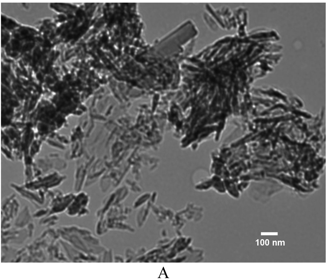
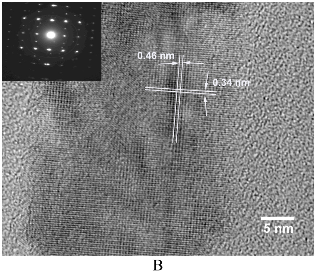
TEM examinations revealed further details of the deposits formed on 10 wt% PLLA fibers at 80°C. They were mainly composed of needle-like HA crystals (Figure 5A, a bright-field image). The high-resolution images revealed the tiny particles to be crystal nuclei of HA (Figure 5B, showing the single crystal image and diffraction pattern from deposits at 80°C). The spacing of crystal lattice planes of 0.46 nm and 0.34 nm match those of HA (110) and (002), respectively.[37]
Figure 5.
A) TEM micrograph of the needle-like HA deposited on PLLA fibers (from 10 wt% PLLA solution) at 3V and 80°C for 60 min; B) The high-resolution micrograph of HA nuclei and its diffraction pattern (inset image).
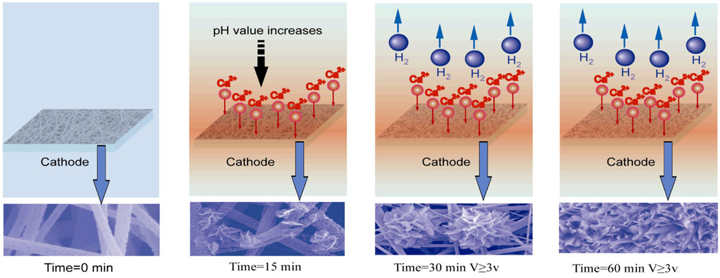
Although the mechanism remains not fully understood, Figure 6 schematically illustrates a hypothesized mechanism for the growth of calcium phosphate crystals on the polymeric nanofibers over time. It is commonly believed that the electrodeposition process involves electrochemical reactions, acid-base reactions and precipitation reactions.[23, 38, 39] The electrochemical reactions on the cathode surface (mainly the reduction of water) result in an increased pH value, invoking the supersaturation of calcium phosphate salts at the vicinity of the cathode where different calcium phosphates, including HA, octacalcium phosphate (OCP) and DCPD, may deposit onto the cathode.[23] In addition, a local concentrated alkaline environment at the vicinity of PLLA nanofibers could facilitate the activation of carboxyl groups by partial hydrolysis of the polymer. The activated anionic group on the polymer surface could lead to enrichment of calcium ions, resulting in rapid nucleation and crystal growth,[19] which was observed when PLLA scaffolds were treated in water before being mineralized in a SBF.[17] The results of attenuated total reflectance Fourier transform infrared (ATR-FTIR) spectra in Figure S4 provide positive evidence for the generation of carboxyl groups on the surface of polymer during electrodeposition. The gradually increasing intensity of vibration bands at 1760 cm−1 and 2990 cm−1 indicates the accumulation of carboxyl groups, which could likely be generated from the hydrolysis of ester bonds in the backbone chain of the PLLA.
Figure 6.
Schematic illustration of a hypothesized mechanism for the growth of calcium phosphate crystals over time. When a deposition voltage is applied, the pH value in the vicinity of electrode increases, and some calcium phosphate crystals deposited onto the surface of PLLA nanofibers. Further increase of deposition time leads to the generation of hydrogen bubbles and larger flower-like crystals.
Although the PLLA nanofibrous scaffold used in our study had a low conductivity, it seemed not to have a significant effect on the migration of the positively-charged ions toward the vicinity of the cathode due to its high porosity. The characteristics of the depositing layer were likely determined by the competition between nucleation and crystal growth steps. Three kinds of nucleation may possibly occur during the electrodeposition process: the heterogeneous nucleation on the substrate surface, further heterogeneous nucleation on the surfaces of as-formed crystals and the homogeneous nucleation in the solution phase.[23, 40, 41] In the present study, nanofibrous scaffolds could have served as a substrate for the calcium phosphate nucleation, crystal growth and assembly into various structures. Therefore the chemical composition, structure, and the surface charge of the scaffold may affect the deposition rate and properties of the deposits. A single large diameter fiber provides a larger surface area for crystal growth than a single small diameter fiber, leading to an increased deposition rate. The electrochemical parameters such as voltage, temperature and pH value of electrolyte may be the most important factors to determine the structure and composition of the resulting coating.[42] A lower deposition voltage provides lower super-saturation condition, which leads to the formation of a small number of heterogeneous nuclei on the substrate and therefore large crystal size (Figure 3B). A moderate deposition voltage induces higher super-saturation conditions in the vicinity of the substrate surface, which not only allows for the formation of adequate heterogeneous nuclei on the surface but also may competitively prevent homogenous nucleation in the solution, providing a favorable environment for compact uniform crystal structure formation (Figure 3C&D). Higher deposition voltage may generate hydrogen bubbles and result in a porous structure (Figure 3E&F). The electrolyte temperature has more complicated effects on the thermodynamic stability and solubility of calcium phosphate, which may favor thermodynamically more stable crystal formation. The higher voltage (increased deposition potential) may have a synergistic effect with the higher temperature (more stable crystal structure) to promote the formation of HA (needle-like or fiber-like crystals).
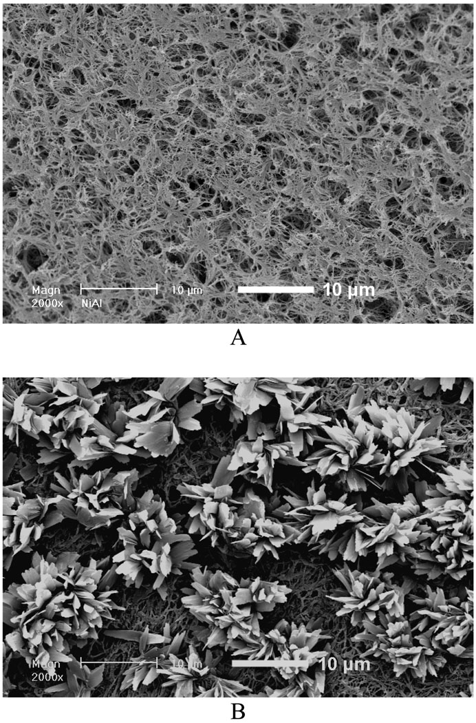
Additionally, in order to expand the application range of the present approach for the rapid mineralization of nanofibrous scaffolds, we have also verified that this method can be applied to mineralize nanofibrous scaffolds prepared by a phase-separation technique[43]. Figure 7 shows the SEM micrographs of phase separated PLLA nanofibrous film before (Figure 7A) and after electrodeposition (Figure 7B). As apparent in Figure 7B, flower-like deposits formed on the surface of scaffold after electrodeposition.
Figure 7.
SEM micrographs of nanofibrous PLLA thin sheets (~40 µm in thickness) prepared by phase separation of a 10 wt% PLLA/THF solution before and after electrodeposition. A) Before electrodeposition; B) After electrodeposition for 30min (3V, 60°C).
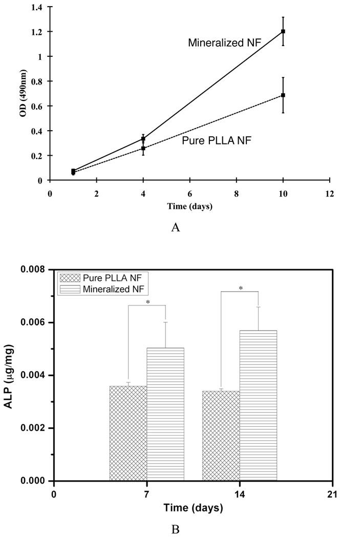
The biocompatibility of the mineralized electrospun nanofibrous scaffolds was evaluated by using pre-osteoblast MC3T3-E1 cells. Figure 8A shows the proliferation behaviors of MC3T3-E1 cells on the mineralized and un-mineralized PLLA nanofibrous scaffolds. After 1 day of culture, the cell numbers were not significantly different between the two types of scaffolds. After 4 days of culture, the cell number was higher on the mineralized PLLA scaffold than on the un-mineralized PLLA scaffold, but the difference was not statistically significant. After 10 days of cell culture, however, there was significantly higher cell number on the mineralized scaffolds than on un-mineralized PLLA scaffolds (p < 0.05). The alkaline phosphatase (ALP) contents of cells on mineralized scaffolds were significantly higher than that on un-mineralized PLLA scaffolds (p < 0.05) after 7 and 14 days of culture (Figure 8B), confirming that the presence of calcium phosphates on PLLA nanofibers enhances osteoblastic differentiation of the cells.
Figure 8.
A) The proliferation of MC3T3-E1 cells cultured on the mineralized (electrodeposition was conducted on 10 wt% PLLA nanofibers at 3V and 60°C for 60 min) and un-mineralized PLLA nanofibrous scaffolds after 1, 4 and 10 days of culture; B) The ALP activity of MC3T3-E1 cells cultured on the mineralized (the same as A)) and un-mineralized PLLA nanofibrous scaffolds after 7 and 14 days of culture (* indicates significance with p < 0.05).
Conclusions
We have developed a straightforward, fast, and versatile technique to fabricate mineralized nanofibrous scaffolds for bone regeneration. Such scaffolds contain a high quality mineralized coating with tailorable surface topography and tunable chemical composition by varying processing parameters, which are capable to mimic the components and architecture of natural bone ECM and provide a more biocompatible interface for bone regeneration.
Experimental
Electrospinning of PLLA nanofibrous scaffolds
PLLA with an inherent viscosity of approximately 1.6 dL/g (weight average molecular weight: 197,000 g/mol) was purchased from Boehringer Ingelheim (Ingelheim, Germany). Other reagents were obtained from Fisher Scientific (Pittsburgh, PA). The PLLA solution was prepared by dissolving PLLA pellets in a mixture of dichloromethane and acetone with a volume ratio of 2:1. The solution was then placed in a 10 mL plastic syringe fitted with an 18-gauge needle. The nanofibers were electrospun at 18kV by using a Gamma high voltage power supply (Gamma High Voltage Research, Inc, Ormond Beach, FL). A SS electrode collector was located at a fixed distance of 15cm from the needle tip. The solution was fed into the needle using a syringe pump (78-0100I, Fisher Scientific, Pittsburgh, PA) at a flow rate of 3 mL/h.
Fabrication of PLLA nanofibrous films by phase seperation
To fabricate thin PLLA nanofibrous sheets, 10 wt% PLLA/tetrahydrofuran (THF) solution was cast into a preheated glass mold. The mold was quickly sealed using a cover glass. The PLLA solution was phase separated at −20°C overnight and then immersed into ice/water mixture to exchange THF for 24 hours. The prepared thin matrix sheets (thickness ~40 µm) were then vacuum-dried for 2 days.
Electrodeposition
Electrodeposition was performed in a 250 mL beaker. The setup for electrodeposition contained two electrodes: a platinum plate electrode (20mm × 20mm × 0.2 mm) served as the counter electrode and the fiber-covered electrode as the working electrode. The distance between the two electrodes was fixed at 2.5 cm. The setup was contained in the beaker and immersed in a water bath to maintain the desired temperature. The electrolyte was a solution of 0.042 mol/L Ca(NO3)2.4H2O and 0.025 mol/L NH4H2PO4, with a pH value of 4.70.
For electrodeposition of phase separated PLLA films, the resulting thin nanofibrous sheets were cut into 1cm×1cm squares, and adhered onto the surface of the SS electrode using copper foil conductive adhesive, followed by electrodeposition at 3V and 60°C for 30 min.
Characterization
The samples were characterized by XRD (Rigaku rotating anode diffractometer), ATR-FTIR (Perkin Elmer 1800), SEM/EDX (Philips XL30 FEG), and TEM (JEOL 3011).
Cell culture and seeding
The thawed mouse calvaria-derived, preosteoblastic cells (MC3T3-E1) were cultured in α-MEM supplemented with 10% FBS, 100 U/mL penicillin, and 100 µg/mL streptomycin in a humidified incubator at 37°C with 5% CO2. The medium was changed every other day.
Two types of scaffolds, including neat PLLA nanofibrous scaffold and electrodeposition mineralized PLLA scaffold, were used for cell seeding and evaluation. Scaffolds were cut into circular disks to fit the well-sizes of multi-well plates (24-well or 48-well culture plates) and soaked in 70% ethanol for 30 min, washed three times with PBS for 30 min each, and twice in cell culture medium for 1 h each on an orbital shaker (3520, Lab-Line Instruments, Inc.). Cells were then suspended and seeded on each scaffold. The constructs were cultured in the humidified incubator with 5% CO2 at 37 °C.
Proliferation assay
For cell proliferation assay, 5×10³ cells were seeded on the scaffolds in 48-well tissue culture plates. MTS assay was carried on days 1, 4, and 10 after cell seeding. Cell proliferation was examined following the CellTiter 96 Aqueous One Solution Cell Proliferation Assay kit (Promega, Madison, WI, USA) instructions. Briefly, 200 µl fresh medium and 40 µl CellTiter 96 Aqueous One Solution Reagent were added to each well, after being incubated at 37 °C for 1.5 h, the solutions were transferred into 96-well cell culture plate. The absorbance was then read at 490 nm with a microplate spectrophotometer.
ALP assay
For ALP assay, 2×10⁴ cells were seeded on each scaffold in 24-well tissue culture plate. 24 hrs after cell seeding, complete medium supplemented with 50 mg/mL ascorbic acid and 10 mM β-glycerol phosphate were added. The medium was changed every other day. ALP activity was measured at 7 and 14 days. ALP was extracted and detected according to the EnzoLyte pNPP Alkaline Phosphatase Assay Kit (AnaSpec, San Jose, CA, USA) instructions. The cell-seeded scaffolds were homogenized in 400 µl lysis buffer provided in the kit. The cell suspension was centrifuged at 10,000×g for 15 min at 4 °C. The supernatant was collected for ALP assay using p-nitrophenyl phosphate (p-NPP) as a phosphatase substrate and alkaline phosphatase provided in the kit as the standard. The amount of ALP in the cells was measured at 405 nm and normalized against total protein content.
Statistical analysis
All experiments were conducted for at least three times and all values were reported as the means ± standard deviations. Statistical analysis was carried out using Student’s t-Test (assuming unequal variance). The statistical difference between two sets of data was considered significant when p < 0.05.
Supplementary Material
Acknowledgements
The research was supported by the National Institutes of Health (NIDCR Research Grants DE015384 and DE017689: PXM), and CH was partially supported by the China Scholarship Council (CSC)/University of Michigan Post-doctoral Program.
Contributor Information
Chuanglong He, Department of Biologic and Materials Sciences, University of Michigan, Ann Arbor, MI, 48109 (USA); State Key Laboratory for Modification of Chemical Fibers and Polymer Materials, College of Chemistry and Chemical Engineering and Biological Engineering, Donghua University, Shanghai, 201620 (P. R. China).
Guiyong Xiao, Department of Biologic and Materials Sciences, University of Michigan, Ann Arbor, MI, 48109 (USA).
Xiaobing Jin, Department of Biologic and Materials Sciences, University of Michigan, Ann Arbor, MI, 48109 (USA).
Chenghui Sun, Department of Biologic and Materials Sciences, University of Michigan, Ann Arbor, MI, 48109 (USA).
Peter X. Ma, Department of Biologic and Materials Sciences, University of Michigan, Ann Arbor, MI, 48109 (USA); Department of Biomedical Engineering, Macromolecular Science and Engineering Center, University of Michigan, Ann Arbor, MI, 48109 (USA).
References
- 1.Ma PX. Adv Drug Deliv Rev. 2008;60:184. doi: 10.1016/j.addr.2007.08.041. [DOI] [PMC free article] [PubMed] [Google Scholar]
- 2.Smith LA, Liu XH, Ma PX. Soft Matter. 2008;4:2144. doi: 10.1039/b807088c. [DOI] [PMC free article] [PubMed] [Google Scholar]
- 3.Wei GB, Ma PX. Advanced Functional Materials. 2008;18:3568. doi: 10.1002/adfm.200800662. [DOI] [PMC free article] [PubMed] [Google Scholar]
- 4.Liu X, Ma PX. Annals of biomedical engineering. 2004;32:477. doi: 10.1023/b:abme.0000017544.36001.8e. [DOI] [PubMed] [Google Scholar]
- 5.Yang F, Wolke JGC, Jansen JA. Chem Eng J. 2008;137:154. [Google Scholar]
- 6.Li D, Xia Y. Advanced Materials. 2004;16:1151. [Google Scholar]
- 7.Agarwal S, Wendorff JH, Greiner A. Advanced Materials. 2009;21:3343. doi: 10.1002/adma.200803092. [DOI] [PubMed] [Google Scholar]
- 8.Huang ZM, Zhang YZ, Kotaki M, Ramakrishna S. Compos Sci Technol. 2003;63:2223. [Google Scholar]
- 9.Zhang SG. Nature Biotechnology. 2003;21:1171. doi: 10.1038/nbt874. [DOI] [PubMed] [Google Scholar]
- 10.Spadaccio C, Rainer A, Trombetta M, Vadala G, Chello M, Covino E, Denaro V, Toyoda Y, Genovese JA. Annals of Biomedical Engineering. 2009;37:1376. doi: 10.1007/s10439-009-9704-3. [DOI] [PubMed] [Google Scholar]
- 11.Huang CB, Chen SL, Lai CL, Reneker DH, Qiu H, Ye Y, Hou HQ. Nanotechnology. 2006;17:1558. doi: 10.1088/0957-4484/17/6/004. [DOI] [PubMed] [Google Scholar]
- 12.Wei G, Ma PX. Journal of Biomedical Materials Research: Part A. 2006;78:306. doi: 10.1002/jbm.a.30704. [DOI] [PubMed] [Google Scholar]
- 13.Kim HW, Lee HH, Knowles JC. J Biomed Mater Res A. 2006;79A:643. doi: 10.1002/jbm.a.30866. [DOI] [PubMed] [Google Scholar]
- 14.Sui G, Yang XP, Mei F, Hu XY, Chen GQ, Deng XL, Ryu S. J Biomed Mater Res A. 2007;82A:445. doi: 10.1002/jbm.a.31166. [DOI] [PubMed] [Google Scholar]
- 15.Chen JL, Chu B, Hsiao BS. J Biomed Mater Res A. 2006;79A:307. doi: 10.1002/jbm.a.30799. [DOI] [PubMed] [Google Scholar]
- 16.Yang DZ, Jin Y, Zhou YS, Ma GP, Chen XM, Lu FM, Nie J. Macromolecular Bioscience. 2008;8:239. doi: 10.1002/mabi.200700221. [DOI] [PubMed] [Google Scholar]
- 17.Zhang R, Ma PX. J Biomed Mater Res. 1999;45:285. doi: 10.1002/(sici)1097-4636(19990615)45:4<285::aid-jbm2>3.0.co;2-2. [DOI] [PubMed] [Google Scholar]
- 18.Zhang R, Ma PX. Macromol Biosci. 2004;4:100. doi: 10.1002/mabi.200300017. [DOI] [PubMed] [Google Scholar]
- 19.Cui WU, Li XH, Zhou SB, Weng J. J Biomed Mater Res A. 2007;82A:831. doi: 10.1002/jbm.a.31187. [DOI] [PubMed] [Google Scholar]
- 20.Li XR, Xie JW, Yuan XY, Xia YN. Langmuir. 2008;24:14145. doi: 10.1021/la802984a. [DOI] [PubMed] [Google Scholar]
- 21.Lu X, Leng Y, Zhang QY. Surf Coat Tech. 2008;202:3142. [Google Scholar]
- 22.Chen SL, Liu WL, Huang ZJ, Liu XG, Zhang QY, Lu X. Mat Sci Eng C-Bio S. 2009;29:108. [Google Scholar]
- 23.Hu R, Lin CJ, Shi HY, Wang H. Mater Chem Phys. 2009;115:718. [Google Scholar]
- 24.Rakngarm A, Mutoh Y. Mat Sci Eng C-Bio S. 2009;29:275. [Google Scholar]
- 25.Cheng XL, Filiaggi M, Roscoe SG. Biomaterials. 2004;25:5395. doi: 10.1016/j.biomaterials.2003.12.045. [DOI] [PubMed] [Google Scholar]
- 26.Liu X, Ma PX. Biomaterials. 2009 [Google Scholar]
- 27.Wei G, Ma PX. Biomaterials. 2009;30:6426. doi: 10.1016/j.biomaterials.2009.08.012. [DOI] [PMC free article] [PubMed] [Google Scholar]
- 28.Damodaran R, Moudgil BM. Colloids and Surfaces a-Physicochemical and Engineering Aspects. 1993;80:191. [Google Scholar]
- 29.dos Santos EA, Farina M, Soares GA, Anselme K. J Biomed Mater Res A. 2009;89A:510. doi: 10.1002/jbm.a.31991. [DOI] [PubMed] [Google Scholar]
- 30.Deligianni DD, Katsala ND, Koutsoukos PG, Missirlis YF. Biomaterials. 2001;22:87. doi: 10.1016/s0142-9612(00)00174-5. [DOI] [PubMed] [Google Scholar]
- 31.Xiao FXB, Liu RF, Zheng YZ. Mater Lett. 2005;59:1660. [Google Scholar]
- 32.Xiao XF, Liu RF, Zheng YZ. Surf Coat Tech. 2006;200:4406. [Google Scholar]
- 33.Montero-Ocampo C, Villegas D, Veleva L. J Electrochem Soc. 2005;152:C692. [Google Scholar]
- 34.Han Y, Fu T, Lu J, Xu KW. J Biomed Mater Res. 2001;54:96. doi: 10.1002/1097-4636(200101)54:1<96::aid-jbm11>3.0.co;2-u. [DOI] [PubMed] [Google Scholar]
- 35.Hou XH, Liu X, Xu JM, Shen J, Liu XH. Mater Lett. 2001;50:103. [Google Scholar]
- 36.Kim HW, Lee HH, Chun GS. J Biomed Mater Res A. 2008;85A:651. doi: 10.1002/jbm.a.31339. [DOI] [PubMed] [Google Scholar]
- 37.Kay MI, Young RA, Posner AS. Nature. 1964;204:1050. doi: 10.1038/2041050a0. [DOI] [PubMed] [Google Scholar]
- 38.Abdel-Aal EA, Dietrich D, Steinhaeuser S, Wielage B. Surf Coat Tech. 2008;202:5895. [Google Scholar]
- 39.Dumelie N, Benhayoune H, Rousse-Bertrand C, Bouthors S, Perchet A, Wortham L, Douglade J, Laurent-Maquin D, Balossier G. Thin Solid Films. 2005;492:131. [Google Scholar]
- 40.Eliaz N. Isr J Chem. 2008;48:159. [Google Scholar]
- 41.Eliaz N, Kopelovitch W, Burstein L, Kobayashi E, Hanawa T. J Biomed Mater Res A. 2009;89A:270. doi: 10.1002/jbm.a.32129. [DOI] [PubMed] [Google Scholar]
- 42.Wang SH, Shih WJ, Li WL, Hon MH, Wang MC. Journal of the European Ceramic Society. 2005;25:3287. [Google Scholar]
- 43.Ma PX, Zhang R. J Biomed Mater Res. 1999;46:60. doi: 10.1002/(sici)1097-4636(199907)46:1<60::aid-jbm7>3.0.co;2-h. [DOI] [PubMed] [Google Scholar]
Associated Data
This section collects any data citations, data availability statements, or supplementary materials included in this article.


