Abstract
Small size ultrahigh Q polymer microrings working at near visible wavelength have been experimentally demonstrated as ultralow noise ultrasound detectors with wide directivity at high frequencies (>20 MHz). By combining a resist reflow and a low bias continuous etching and passivation process in mold fabrication, imprinted polymer microrings with drastically improved sidewall smoothness were obtained. An ultralow noise-equivalent pressure of 21.4 Pa over 1–75 MHz range has been achieved using a fabricated detector of 60 μm diameter. The device’s wide acceptance angle with high sensitivity considerably benefits ultrasound-related imaging.
Ultrasound-related medical imaging is a noninvasive modality and has become increasingly popular. High-resolution ultrasound and photoacoustic imaging, achieved by operating at high frequencies (>20 MHz), can provide accurate analysis and diagnosis in medical imaging. Such noninvasive modality is an excellent tool for small animal studies and intravascular imaging.1, 2 To detect high-frequency ultrasound wave, a detector with both wideband response and small element size is needed. Small device size minimizes the spatial averaging effect for high-frequency waves, which is essential for high-resolution imaging. For example, phased-array imaging systems working at a center frequency of 30 MHz require λ∕2 element size and spacing on the order of 25 μm, where λ is the acoustic wavelength. Another example is that the small device size for tomographic imaging provides high resolution and high contrast over a large imaging region.3, 4 Although the piezoelectric material polyvinylidene fluoride (PVDF) based needle hydrophones can reach the requirement of wide bandwidth and small element size [e.g., 40 μm (HPM04∕01, Precision Acoustics, Dorchester, Dorset, UK)], the device has poor sensitivity: the noise-equivalent pressure (NEP) is relatively high ∼10 kPa, which seriously limits the imaging depth. Moreover, arrays with small element size and spacing and large element count, required for real-time imaging, are very difficult to realize using piezoelectric transducers because of the increased noise level, complexity of electrical interconnects, and fabrication challenges.
Optical detection of ultrasound5, 6, 7, 8, 9, 15 could potentially address the above issues. It can achieve a low NEP (⪡1 kPa) with relative small element size and wideband response,8 and would be easier to create dense arrays with small element size.17 We have been exploiting polymer microring resonators as ultrasound detectors, and have demonstrated a low NEP of ∼230 Pa over a wide bandwidth of 1–75MHz even with a relatively low cavity Q factor of 6000 in the past.8 Besides, a flat frequency response from dc to over 90 MHz at −3 dB was calibrated by a wideband photoacoustic source.8 With improved fabrication, further reduction in device’s NEP (∼88 Pa) has been realized using a higher Q factor microring device.9 However the device diameter (D) was still around 100 μm, limiting the high-resolution imaging applications. Smaller microrings were shown to suffer from higher surface scattering loss, leading to a lower Q factor and decreased sensitivity. The goal of this work is to reduce the device size but without sacrificing the cavity Q and therefore the device’s sensitivity. To achieve this, we have shifted the device’s working wavelength from NIR to 780 nm wavelength range in order to reduce the water and polymer absorption effect. However developing a process to fabricate microrings with a very smooth sidewall is the key to achieve small device size with low NEP.
In what follows, we will show a fabrication process to achieve the polymer microring’s Q factor as high as 4×10⁵ with ring’s D=60 μm. When used as an optical ultrasonic hydrophone, ultralow NEPs of 10.5 Pa, 15.2 Pa, and 21.4 Pa for 1–25 MHz, 1–50 MHz, and 1–75 MHz ranges have been measured, respectively. The device’s angular response was characterized to prove its wide directivity, 40° for −6 dB beamwidth at 20 MHz. Even smaller devices (D=40 μm) were also fabricated and characterized to further extend their applications to 30 MHz.
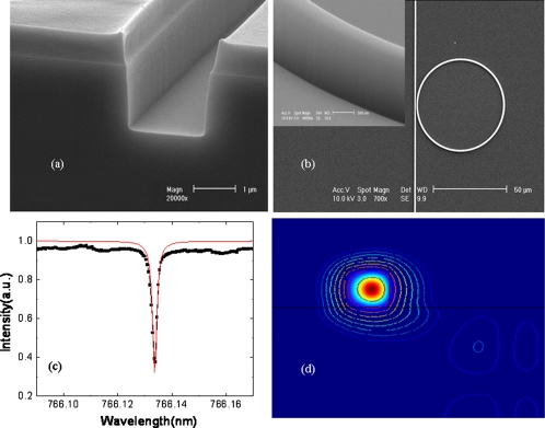
The ultrahigh Q polymer microrings in this work are fabricated by nanoimprint technique10 using a silicon mold with smooth sidewalls. The silicon mold fabrication process begins with electron beam lithography to create patterns of microrings and straight bus waveguides in the e-beam resist. After the resist development, a thermal reflow process is applied to the resist patterns.11 By choosing suitable temperature and time duration, this reflow process can greatly reduce imperfections in the polymethyl methacrylate (PMMA) resist patterns and harden the edge of the resist. Optimal temperature and heating time were found to be 115 °C and 90 s, respectively. Next the resist patterns were transferred into the silicon layer using SF6 gas and C4F8 gas based inductively coupled plasma reactive-ion etch (RIE) on a Surface Technology Systems deep silicon etcher system. A low platen bias was used in the etching recipe to reduce the damage to the reflowed PMMA mask and the SF6 gas and C4F8 gas flow were optimized to minimize the sidewall roughness.12 Figure 1a shows the etched smooth sidewall silicon trench with the resist remained on top. After RIE, the rest of PMMA mask is removed in hot acetone. A combination of resist reflow and modified Bosch process for Si etching are the keys to produce silicon master with smooth sidewalls.
Figure 1.
(a) SEM picture of the silicon trench mold fabricated using optimized fabrication process showing smooth sidewalls, (b) SEM picture of an imprinted polymer microring coupled with a straight waveguide, and inset shows the sidewall of the imprinted polymer microring, (c) normalized transmission spectrum of polymer microring with D=60 μm, and (d) simulated electrical field intensity distribution a polymer microring waveguide with D=60 μm.
The detail of using the nanoimprint process to create polystyrene microrings can be found in Ref. 10. Figure 1b shows the top view of a scanning electron microscopy (SEM) picture of a polystyrene microring resonator with a diameter D=60 μm coupled to a straight waveguide. The inset shows the SEM picture of the sidewall of the imprinted polymer microring. The smoothness is dramatically improved as compared with our previous results. The device’s transmission spectrum was measured using a tunable laser (New Focus TLB-6312) with tuning range from 765 to 781 nm. A single mode fiber (Nufern 780-HP) and a conventional multimode fiber were aligned to the input and output waveguide, respectively. The polarization of the input light was controlled by a fiber based optical polarization controller; and for consistency the input light was fixed as TE polarization. The output light signal from the multimode fiber was measured by a photodetector. The measured transmission spectrum in de-ionized water [in Fig. 1c] shows a sharp resonance dip with a Q factor of 4×10⁵. The device’s intrinsic loss of 1.1 dB∕cm is extracted from the transmission spectrum, which implies an intrinsic cavity Q factor of 5.1×10⁵. To better understand the loss mechanism in our microring devices, the bending loss and leakage loss are studied by finite element method using COMSOL.13 The electrical field intensity distribution in the polymer microring waveguide (with ring diameter D=60 μm, waveguide height=1.4 μm, and width=1 μm) is simulated and shown in Fig. 1d. We can clearly see that the electrical filed is well confined in the ring waveguide region and only a very small amount of field leaks to the substrate due to the bending induced loss in the ring waveguide. The bending and leakage loss limited Q is obtained to be 107 and the material absorption14 limited Q can be also as high as 107, so we believe that the Q factor of our current 60 μm polymer microrings is still limited by the surface scattering loss, which can be further improved in the future.
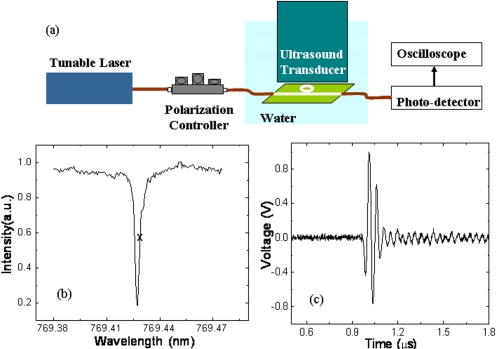
The experimental setup used to characterize the device’s acoustic sensitivity was shown in Fig. 2a. The microring resonator detector was immersed in de-ionized water which served as top cladding of the microring and coupling medium for acoustic wave. The output wavelength of light from the tunable laser was set to 769.4285 nm where the resonance transmission curve has the highest slope. The laser power from the input fiber was about 2 mW and a ∼120 μW laser power was coupled into the input waveguide. The output power was collected by a multimode fiber which is connected a low-noise photodetector (New Focus, 1801-FC). The photodetector output is connected to an oscilloscope to collect the data. A 20 MHz unfocused transducer (V316, Panametrics NDT, Waltham, MA), driven by a 5 V peak-to-peak one cycle 20 MHz sinusoidal wave with an output peak pressure of 15 kPa, was used to insonify the microring. The generated peak pressure was calibrated by a commercial hydrophone (HGL0085, ONDA Corp., Sunnyvale, CA). When the acoustic pressure pulse hits on the polymer microring, it modulates the resonance wavelength and thereby the output power at fixed probing wavelength. Figure 2c shows the recorded signal trace from a single-shot acoustic wave. The device produces an output of 1000 mV with an input of 15 kPa peak acoustic pressure, which means the device’s acoustic sensitivity is around 66.7 mV∕kPa. The root-mean-square noise levels were 0.7 mV, 1.01 mV, and 1.43 mV over 1–25 MHz, 1–50 MHz, and 1–75 MHz bandwidth, respectively, leading to NEPs of 10.5 Pa, 15.2 Pa, and 21.4 Pa at the corresponding bandwidth. Extrapolating the sensitivity from ∼20 MHz to higher frequencies is valid since all bands are well below the −3 dB detection bandwidth of the device. Compared to our published best results,7 88 Pa over 1–75 MHz, we have further improved the NEPs by over fourfolds. This result is 16 times better than the best Fabry–Perot cavity based optical ultrasound detector15 and 300 times better than the similar size piezoelectric PVDF transducer (HPM075∕1, Precision Acoustics, Dorchester, Dorset, UK). Since our simulation results show that the device’s intrinsic Q can be as high as 107, we anticipate that the device’s NEP can reach single digit Pa by further improving the fabrication and increasing the device’s Q factor. Detectors with such ultralow NEPs will directly benefit the ultrasound and photoacoustic imaging to significantly increase the imaging depth. It also pushes the photoacoustic imaging toward clinical applications on humans because much lower laser fluence is required.
Figure 2.
(a) Experimental setup to measure the acoustic sensitivity of polymer microring ultrasonic detector, (b) normalized transmission spectrum of polymer microring merged into DI water, the operating wavelength position is marked with “X,” and (c) a single shot of acoustic wave measured by high Q polymer microring.
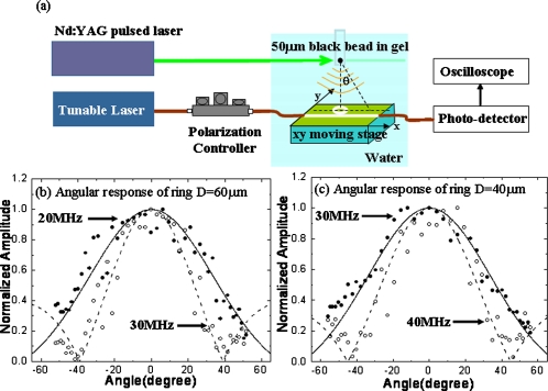
The angle-dependent sensitivity of the polymer microring was characterized using a photoacoustic method. Figure 3a shows the schematic of the experimental setup. A 50 μm polystyrene black bead embedded in the gel was illuminated by a pulsed, frequency-doubled neodymium:yttrium aluminum garnet (Nd:YAG) laser at 532 nm wavelength with pulse duration of 6 ns (Surelite I-20, Continuum, Santa Clara, CA). The energy from the pulsed laser was efficiently absorbed by the black bead, generating a spherical acoustic wave by the optoacoustic effect. The photoacoustic wave was then detected by the polymer microring detector at a distance of about 3 mm from the bead. The detectors, with diameters of 60 (Q=4×10⁵ and NEP∼21.4 Pa) and 40 μm (Q=7×10⁴ and NEP∼100 Pa), are linearly scanned to receive the photoacoustic signals at different angles. Band-pass filters centered at different frequencies are applied to the recorded signals at different angles to extract the signal levels at those frequencies. The theoretical angular response can be described by considering a ring transducer:16D(θ)=J0(ka sin θ), where k is the wave vector of the incident acoustic wave, a the radius of the ring transducer, and θ the incident angle of the acoustic wave. Figure 3b, 3c show the theoretical and experimental angular responses of the polymer microring with a diameter D=60 and 40 μm, respectively. The theoretical curves fit well to our experimental data.
Figure 3.
(a) Experimental setup to measure the angular response of the polymer microring, experimental data (dot) and theoretical calculation (line) of angular response of the polymer microrings with D=60 μm at 20 MHz (solid dot and line) and 30 MHz (empty dot and dashed line) (b), and with D=40 μm at 30 MHz (solid dot and line) and 40 MHz (empty dot and dashed line) (c).
For beam-forming applications, the detector’s angular response should have −6 dB beamwidth of 40°.17 Under this criterion, the microring detectors with D=60 and 40 μm can be used as an imaging element for acoustic central frequency of 20 MHz and 30 MHz, respectively. Compared to our previous polymer microring hydrophone with D=100 μm, working around 10 MHz range, the new detectors have doubled and tripled the frequency range with better or similar sensitivity, corresponding to resolutions of 75 μm and 50 μm, respectively. The small size device will also benefit the tomographic imaging, enabling a uniformly high resolution and high contrast over a large region of interest. Using the single-element low-noise small size detector with linear translation stages, we have shown high-resolution photoacoustic imaging applications by synthetic one-dimensional and two-dimensional microring arrays. The details can be found in our recent work.4
In conclusion, a fabrication process has been developed to fabricate small device size (D=60 μm) polymer microring with significantly improved smooth sidewalls and Q factor. By using such high Q polymer microring as an ultrasonic hydrophone, a record low NEP (around 21.4 Pa) has been achieved over 1–75 MHz frequency range. The smaller sizes of 60 μm and 40 μm microring improve the resolutions to about 75 μm and 50 μm, respectively, for beamforming applications. Fabrication of even smaller size detectors (e.g., 20 μm detector for 50 MHz applications) with high sensitivity is possible by using higher index polymers to reduce the bending-induced radiation loss. Previously, we fabricated a four-element microring array17 to show the feasibility of a linear microring array. The microring array with more elements and smaller element size is part of our ongoing work. Microrings with high sensitivity and wideband response can also benefit photoacoustic microscopy application in imaging depth and axial resolution.18
Acknowledgments
This work is supported by NIH Grant No. EB007619. We would like to thank Tzu-Yin Wang for assistance on transducer calibration.
References
- Foster S. F., Pavlin C. J., Harasiewicz K. A., Christopher D. A., and Turnbull D. H., Ultrasound Med. Biol. 26, 1 (2000). 10.1016/S0301-5629(99)00096-4 [DOI] [PubMed] [Google Scholar]
- Sethuraman S., Aglyamov S. R., Amirian J. H., Smalling R. W., and Emelianov S. Y., IEEE Trans. Ultrason. Ferroelectr. Freq. Control 54, 978 (2007). 10.1109/TUFFC.2007.343 [DOI] [PubMed] [Google Scholar]
- Xu M. and Wang L. V., Phys. Rev. E 67, 056605 (2003). 10.1103/PhysRevE.67.056605 [DOI] [PubMed] [Google Scholar]
- Chen S. -L., Ling T., and Guo L. J., J. Biomed. Opt. 16, 056001 (2011). 10.1117/1.3573386 [DOI] [PMC free article] [PubMed] [Google Scholar]
- Ashkenazi S., Hou Y., Buma T., and O’Donnell M., Appl. Phys. Lett. 86, 134102 (2005). 10.1063/1.1896085 [DOI] [Google Scholar]
- Ashkenazi S., Chao C. Y., Guo L. J., and O’Donnell M., Appl. Phys. Lett. 85, 5418 (2004). 10.1063/1.1829775 [DOI] [Google Scholar]
- Beard P. C. and Mills T. N., Electron. Lett. 33, 801 (1997). 10.1049/el:19970545 [DOI] [Google Scholar]
- Huang S. W., Chen S. L., Ling T., Maxwell A., O’Donnell M., Guo L. J., and Ashkenazi S., Appl. Phys. Lett. 92, 193509 (2008). 10.1063/1.2929379 [DOI] [PMC free article] [PubMed] [Google Scholar]
- Ling T., Chen S. L., and Guo L. J., Opt. Express 19, 861 (2011). 10.1364/OE.19.000861 [DOI] [PMC free article] [PubMed] [Google Scholar]
- Chao C. Y. and Guo L. J., J. Vac. Sci. Technol. B 20, 2862 (2002). 10.1116/1.1521729 [DOI] [Google Scholar]
- Borselli M., Johnson T. J., and Painter O., Opt. Express 13, 1515 (2005). 10.1364/OPEX.13.001515 [DOI] [PubMed] [Google Scholar]
- Gao F., Wang Y., Cao G., Jia X., and Zhang F., Appl. Phys. B: Lasers Opt. 81, 691 (2005). 10.1007/s00340-005-1951-x [DOI] [Google Scholar]
- Oxborrow M., Proc. SPIE 6452, 64520J (2007). 10.1117/12.714954 [DOI] [Google Scholar]
- Schwesyg J. R., Beckmann T., Zimmermann A. S., Buse K., and Haertle D., Opt. Express 17, 2573 (2009). 10.1364/OE.17.002573 [DOI] [PubMed] [Google Scholar]
- Zhang E. D. and Beard P., Proc. SPIE 5320, 222 (2004). 10.1117/12.531160 [DOI] [Google Scholar]
- Blackstock D. T., Fundamentals of Physical Acoustic (Wiley, New York, 2000). [Google Scholar]
- Maxwell A., Huang S. W., Ling T., Kim J. S., Ashkenazi S., and Guo L. J., IEEE J. Sel. Top. Quantum Electron. 14, 191 (2008). 10.1109/JSTQE.2007.914047 [DOI] [PMC free article] [PubMed] [Google Scholar]
- Xie Z., Chen S. -L., Ling T., Guo L. J., Carson P. L., and Wang X., Opt. Express 19, 9027 (2011). 10.1364/OE.19.009027 [DOI] [PMC free article] [PubMed] [Google Scholar]


