Abstract
Real-time stereovision-guidance has been introduced for efficient and convenient fractionated stereotactic radiotherapy (FSR) and image-guided intensity-modulated radiation therapy (IMRT). This first pilot study is to clinically evaluate its accuracy and precision as well as impact on treatment doses. Sixty-one FSR patients wearing stereotactic masks (SMs) and nine IMRT patients wearing flexible masks (FMs), were accrued. Daily target reposition was initially based-on biplane-radiographs and then adjusted in six degrees of freedom under real-time stereovision guidance. Mean and standard deviation of the head displacements measured the accuracy and precision. Head positions during beam-on times were measured with real-time stereovisions and used for determination of delivered doses. Accuracy ± precision in direction with the largest errors shows improvement from 0.4 ± 2.3 mm to 0.0 ± 1.0 mm in the inferior-to-superior direction for patients wearing SM or from 0.8 ± 4.3 mm to 0.4 ± 1.7 mm in the posterior-to-anterior direction for patients wearing FM. The image-guidance increases target volume coverage by >30% for small lesions. Over half of head position errors could be removed from the stereovision-guidance. Importantly, the technique allows us to check head position during beam-on time and makes it possible for having frameless head refixation without tight masks.
Keywords: Fractionated stereotactic radiotherapy (FSR), Intensity modulated radiotherapy (IMRT), Image-guided radiation therapy (IGRT), Stereovision (3D video imaging)
Introduction
Accurate and precise head positioning have always been the central characteristics of intracranial stereotactic radiation surgery (SRS) and fractionated stereotactic radiotherapy (FSR). Traditionally, these were achieved through using a head-ring (1, 2) screwed onto the patient’s skull and a localizer locked to the head-ring during the CT/MRI scanning. This method corrects small head movements during a CT or MRI scan according to the images of the localizer fiducials. The head-ring or frame and patient’s head are then precisely fixed onto the treatment machine. This minimally invasive frame-based head refixation has a high isocenter setup accuracy of ~1 mm (3–9). Still, patients who had previously underwent FSR found that they could not tolerate the head ring on their skulls for long periods of time. Thus, noninvasive head refixation using either a removable-frame (10–14), a mask (15–20), or image-guidance (21–31) was developed for FSR. Currently, tight head holders (masks) and X-ray image verification using either biplane radiograph or cone-beam CT scans are the most popular forms used in FSR. For example, a popular stereotactic mask (SM) (BrainLAB Inc., Heisenberg, Germany) was made of thick-thermoplastic pieces of one back piece supported by a rigid headrest and two-layered front pieces. The three pieces were clapped tight onto two carbon-fiber sidebars. The sidebars and the headrest are rigidly fixed on an adjustable couch mount. After daily head refixation on the treatment table, biplane radiography (or cone-beam CT scans) can be taken and matched with reference images (29–31) to determine target displacement. In a retrospective analysis, we have found that biplane-radiograph-based head refixation has the uncertainty of 2.3 mm (32). The accuracy is adequate for FSR using circular cones that usually produce round-shaped isodose surface with >2-mm margin around the target. Nowadays, more conformal dose distributions with no margin around the target can be designed with use of micro-multileaf-collimator (micro-MLC). Thus, the target coverage is subject to the small position errors.
To detect the small head displacements prior to and during each beam/arc irradiation, we have introduced a stereovision-guided FSR (33–37). In such a system, 3D surface images are captured using a 3D-video camera that was mounted on the ceiling of the treatment vault. The head position errors were automatically determined through the alignment of the real-time surface with the reference surface. Theoretically, 3D-surface-guidance inhere a similar accuracy to those of other optical-marker-based systems (23–28). Practically however, there are concerns of (a) the effects of skin-tone and room-lighting on the stereovisions of patients, (b) head displacements relative to the masks, (c) variations of patient’s hair and facial expressions, (d) weight loss or graduate surface shape changes in the course of treatment, and (e) patient motion during beam-on time. To deal with these issues, the first clinical trial with Johns-Hopkins University School of Medicine (JHUSM) institutional review board (IRB) approval was completed. This report presents the results of accuracy and precision as well as potential benefits of the stereovision-guided FSR and IMRT.
Materials and Methods
Eighty-six patients were accrued in a pilot study of “3D-video-guided target repositioning and volumetric monitoring” at JHUSM. Twelve non-FSR patients and four early FSR patients who were at the time receiving incomplete stereovision-guidance were excluded from this study. Table I lists the characteristics of the remaining 70 patients, of which, 61 are wearing BrainLAB SMs undertaken FSR and 9 are wearing the conventional flexible facemasks (FM) (Med-Tec U-frame, Med-Tec Inc., Orange City, IA) undergone IMRT. For FSR patients, personalized SMs were made at CT simulation according to patient head contours. A BrainLAB or BRW (RADION-ICS, Burlington, MA) stereotactic localizer is then attached for CT scanning. The transverse CT slices are imported, localized, and fused with T1-weighted magnet-resonant images (MRI) in a stereotactic planning system (BrainSCAN v4.2 or later versions, BrainLAB Inc., Heisenberg, Germany). The CT images serve as the primary image set for dose calculations and position verifications while the fine-section MRI usually provided better definitions of the target and critical structures. Intensity modulated beams are used for large or irregular tumors while conformal arcs are selected for small or rounded targets. A Varian 6EX linear accelerator (Varian Inc. Palo Auto, CA) with a re-attachable BrainLAB-micro-MLC (m3) is utilized for dose delivery. The isocenter is usually located at the center of the target and the collimator with the m3 is rotated to provide the conformal shape of the field to the target. Typical prescription doses were 5 Gy/fraction at 80% isodose with total 5 fractions for small acoustic neuroma, or 5.0 to 1.8 Gy/fraction at ~90% isodose line with total 5 to 38 fractions for other tumors. The nine patients wearing FM used the same planning system but localized with skin markers. Two of the patients wearing FM could not tolerate the tightness of the SM that was desired. For all patients, the isocenter setup used the following procedures.
Table I.
Characteristics of the 70 FSR Patients Undertaken the Stereovision-Guided FSR.
| RM | FM | |
|---|---|---|
| Number of patients | 61 | 9 |
| Age (y) Median (range) | 54 (21–83) | 54 (20–79) |
| Male : Female | 24:37 | 3:6 |
| Skin-tone White : Dark : Others | 53:5:3 | 6:2:1 |
| Diseases (number of patients)* | AN (30), ME (14), BM & other (17) | SB (2), GBM (2), ME (1), Other (4) |
| Number of Fractions | 5–10, 5–32, 5–35 | 38, 5–8, 32, 10–34 |
AN – Acoustic Neuroma; ME – Meningioma; BM – Brain Metastases; SB – Skull-Base tumor; GBM – Glioblastoma; Other – include basal cell carcinoma, melanoma, Pituitary Adenoma, recurrent medulloblastoma, recurrent Astrocytoma, and recurrent Ependymoma.
Conventional Mask-Based Radiograph-Verified Head Refixation
At the daily setup, the patient’s head was placed within the mask and realigned with the room lasers. For any FSR patient, isocenter was also checked with a re-attachable BrainLAB head position box that had the planned isocenter marks and the projections of individual beams (or at the start and the end of arcs). A pair of anterior and lateral radiographs were then taken and matched with the corresponding DRRs (31). The isocenter setup errors were determined by the central field displacements when the outlines of anatomic mark on the DRRs were matched with the those edges on the portal films. The detected isocenter errors were corrected and rechecked. The final isocenter on the first day was then marked on the mask for the later daily setup. Radiograph verification and position adjustment were performed every day for patients with total fractions of ≤10. Results of the retrospective analysis on 103 sets of daily-setup radiographs on 17 patients (32) revealed a standard deviation of ~2 mm in individual directions. Thus, a more accurate and precision-guided technique was introduced.
A Noninvasive Stereovision-Guided Head Refixation
A stereovision-guided head refixation system, shown in Ref. (34), correlates the target position in the CT-based plan with the real-time treatment positions using surface images. Following the conventional daily setup, surface images of patients can be rapidly captured using a prototype 3D Rainbow camera (Genex Inc., Kensington, MD) mounted on the ceiling of the treatment vault. The real-time image is semi-automatically matched with a reference at the planned position. The head position errors are then corrected through the adjustment of the couch and couch mount. The head positions during irradiation of individual beams (or arcs) can also be verified with real-time surface images. This stereovision guidance consists of a 3D camera controlled by a computer and image registration software. As described previously (33), the prototype 3D camera is made of a rainbow light projector and two CCD cameras with focal lengths of ~184 cm from the lens to the Linac isocenter. The two cameras are separated by 65 cm to view the patient’s head from different angles. All 3D surface points in the view of a CCD camera (image matrix of 480 × 640) are determined by an analytical solution based on the modified triangular principle (34, 35). Therefore, a full frame of 3D surfaces can be captured in one snapshot. All surface images are registered in the fixed machine coordinate system with an accuracy of ~0.5 mm (36, 37). A modified iterative close-point alignment (ICP), previously described in reference 34, has been built in the camera control program to automatically match the surface images that determine the head displacements relative to the desired position. For patients wearing SMs, small 3D translations, pitch rotations, and roll rotations are provided through the BrainLAB couch-mount. The yaw rotation is obtained through the adjustment of the Linac table angle. All rotation corrections are carried out first since a small rotation by the couch-mount yields a large displacement for the frontal surface. According to the ICRU 42 (38) or IEC convention for the Linac coordinates, we had chosen the origin at the isocenter, X-axis toward to the patient left, Y-axis to the gantry, and Z-axis to the front of the patient who was supinely positioned. For any patient wearing FMs, Med-Tec Type-S head-extension boards for the Varian Exact™ couch are used and the rotational errors are manually corrected. Each adjustment is then verified through recaptured surface images. The final head positions should have an isocenter shift <1 mm and head rotation <1 degree. On average, two to three surface images are taken to obtain the desired final position.
Ensuring and Validating Surface Rigidity
Clinically, facial expressions such as the mouth, nose, and eye movements might affect surface shape and location. These intra-fractional motions are continuously monitored through a real-time plot of the intersection point between the surface and a projection light ray (34). The projection light ray points to the area of interest such as the inferior portion of the chin to monitoring the mouth movement. A reliable surface image is captured when the plot of the intersection point becomes stable and no abnormal facial expression appears in a 2D live-video view. The overexposure and patient skin-tone effects could be minimized by selecting the light intensity by choosing proper power to the projector lamp. The shadow effect is avoided by using the surface area with jumps of <1 cm in neighboring surface points. The room lighting has less effect on Rainbow cameras. In capturing an image with normal room lighting condition, users can select a low power in the range of 40% to 100% for bright-white subjects and high power in the range of 120% to 240% for dark-black subjects.
To validate the rigidity of surfaces of patients, the rigidity of several identifiable points on head surface is measured during the course of treatment. Since surface matching provides us with the patient’s head rotation angles around the three axes as (ωx, ωy, ωz) and an isocenter-shifts along the axes (σx, σy, σz) from the reference surface to the real-time surface. The location of any point P′ (x′, y′, z′) in the real-time surface can be predicted, base-on rigid surface matching, from its corresponding point P(x, y, z) in the reference surface by
| [1] |
Considering rotation errors (ωx, ωy, ωz) <3° (0.053 radian), their cosine values can be approximated by 1 and their sine values close to (ωx, ωy, ωz) in radian, respectively. Thus,
| [2] |
Ignoring the second and third orders of the small angles, we have the rigid surface point
| [3] |
Where R is the rotation vector of (ωx, ωy, ωz) and R × P is vector cross product. When a point is measurable on real-time surface as Pm, its deviation from the rigid surface point is then give by
| [4] |
If the displacement is <2 mm, the surface area at the point is considered as rigid.
Estimating Accuracy, Precision, and Efficiency
To a patient who has total image days of M during the course of FSR, the image sets at the initial setup, final position, and during beam-on time would include images of m = 1,2, … M. The head positioning errors at each specific set can be estimated by the mean and standard deviation (SD) of the isocenter-translation or head-rotation in a given direction as
| [5] |
To a group of patients, position errors were usually considered as random variables. The group position accuracy can be measured by the average accuracy among all patients in the group. The group precision is then estimated by the SD of the mean values of patients plus the average SD of individual patients. Thus, we have
| [6] |
where N is the number of patients in the group of g = RM or FM. The confidence interval for this estimate of accuracy and precision is determined by the percentage of the number of patients who have larger personal setup errors (ε̂p > σ̂g) in the group.
The surface images taken after the initial setup are used to measure the uncertainty of the conventional stereotactic head refixation. The surface images taken at the final setup positions are used to measure the uncertainty of the stereovision-guided head refixation. The surface images taken during the beam-on time are used to measure the target positions during the dose delivery. On average, seven to eight daily surface images are taken and stored per patient. Images and results of adjustments are saved for the 70 patients included in the analysis.
Dosimetric Impact
Composite plans are created by adding beams with the daily isocenter shifts for the initial setup or final positions through entire course of treatment. The delivered dose to the tumor and critical structures for a group of patients are evaluated by the average values on tumor coverage and the doses decrease on the hot spot for nearby critical structures. Difference of dose-volume histograms (DVHs) between the composite plans at the positions prior-to and post-to surface-guided alignment illustrates the dosimetric impact. The post-aligned DVHs slightly differ from that of the original plan that has no daily displacement.
Results and Discussion
Accuracy of Stereovision Guided System
Systematic tests with Rando head phantom wearing SM and FM as well as no mask have been performed to measure the system uncertainties prior to clinical applications. The system accuracy and precision of 0.2 mm on detecting isocenter shifts and of 0.2 degree on detecting head rotations have been achieved in repeated measurements even after a few months. There is no difference among results with SM, FM, and no masks since there is no motion for phantom.
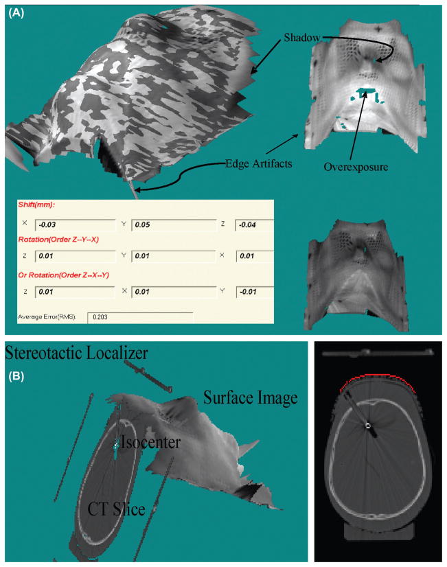
Lighting condition is vitally important in video imaging. Figure 1 illustrates the artifacts of overexposure, shadow, and dark areas on the surface images of a head phantom inside a SM. The upper-left, upper-right, and bottom-right of Figure 1(A) shown typical fused, real-time, and reference surface images, respectively. The bottom-left of Figure 1(A) illustrated the surface displacements according to the stereovision guidance. The overexposure artifacts, shown as missing areas at the bright surface regions, are major concern because most digital cameras at high light intensities have narrow latitudes. Thus, any polishing surface that has strong light reflection should be covered by the tapes. The shadow artifacts occurring in the shadow areas of the projecting light that have no reflection. The dark skin surface inside the mask can be reconstructed if the lamp power is increased. There are less underexposure effects due to the large latitude of the digital cameras at low light intensities. The direct overlays of grayscale pictures of the same CCD camera onto the 3D surface provide the texture information. Usually, bright room light and high projector power results in bright 3D surface images, and dim room light and low projector power would yield dark surface images. Although surface image brightness is changed with the room light, projector light strength, and object surface brightness, results shown in Figure 1(A) (dark Rando phantom in white mask) demonstrate that the surface geometry has little changed if the proper projection light power is used.
Figure 1.
Illustration of 3D video imaging artifacts and typical stereovision-guided results (inserted table) from alignment of surface images of a head phantom in RM without movement but different lighting conditions (A) and the geometry relationship and small differences between CT images (slices) and surface image (B).
Edge artifacts are introduced at the interpolation of these surface points at the edges and the artifacts can simply be removed by limiting the size of the distance between the neighboring points. Importantly, unreliable surface areas covered by hairs or clothes must be cut off. The remaining surface areas should adequately overlap with the reference surface for the surface alignment.
Feasibility of Stereovision Imaging on Patients
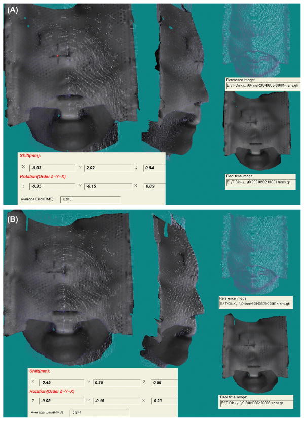
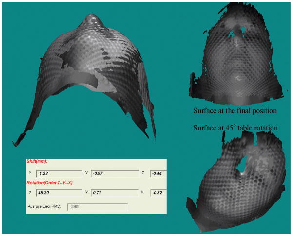
Small differences between the reference CT surface and the real-time video surface are illustrated in Figure 1(B) for the phantom images. The small difference (~1 mm) is due to the partial volume effect in CT-volume rendering and shadow artifacts in the real-time-video images at the edges of the mask nets or holes. The differences are consistent in repeated tests and can be corrected by matching the CT surface and video surface taken at the same position. To eliminate this small effect in the first trial, the video-surface image is selected at the first approved position as the reference image for all patients. Figure 2 demonstrates that the rotation angle is typically controlled within 0.5 degrees and the isocenter shifts could be improved from 2 mm to 0.5 mm for patients wearing SMs. Figure 3 illustrates that the lateral shift of >1 mm had been detected for a patient wearing a FM after a 45 degree table rotation although no position errors had been detected with radiograph and stereovision prior to the table rotation. The real-time stereovisions have been achieved on all of the seventy patients. Thus, the proposed stereovision guidance is clinical feasible. In comparison with radiographic verification of daily setup for the 70 patients, the real-time stereovision-guidance has not caused any incorrect position indication.
Figure 2.
A patient initial setup (A) and final position (B) errors determined by the real-time surface guidance.
Figure 3.
Patient head displacement (1.2 mm laterally) after 45 degree table rotation detected by the real-time stereovision guidance.
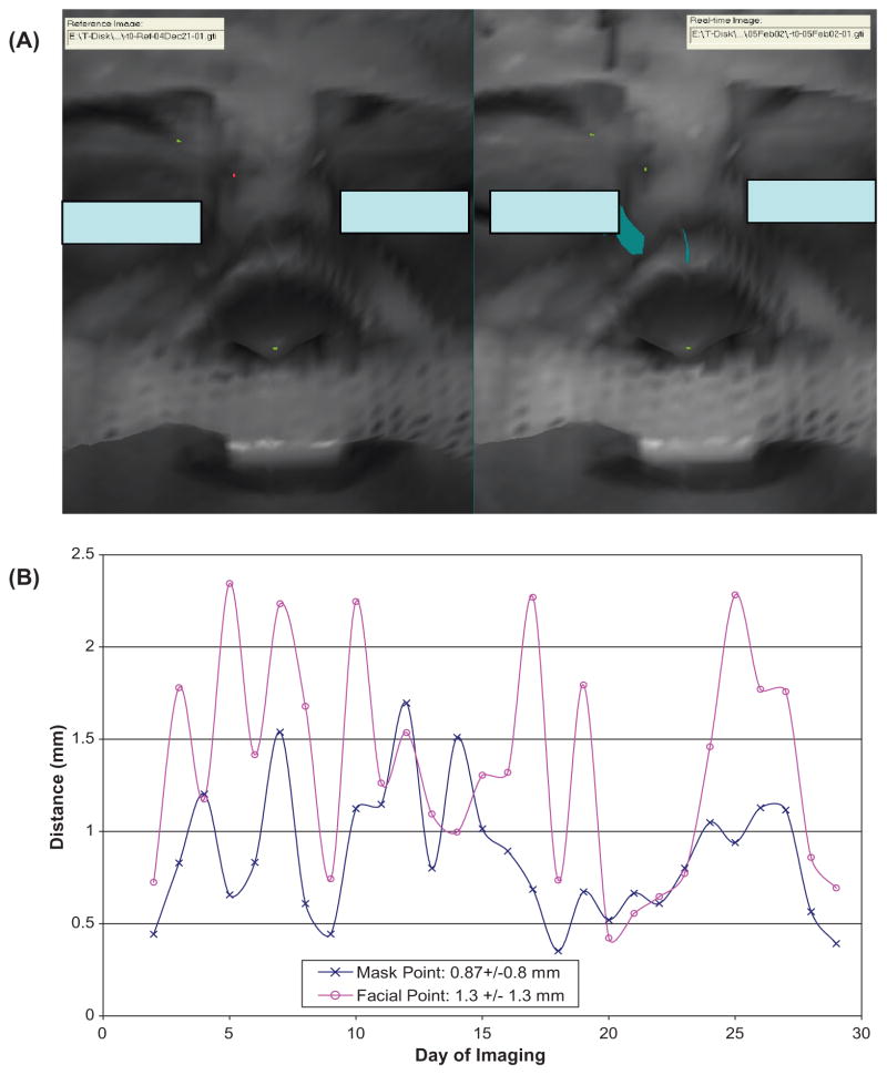
To evaluate the surface rigidity, the displacements for the skin marks and the setup marker on the facemask as shown in Figure 4(A) are measured. Small distances (~2 mm) between the measured and predicted locations confirm the surface rigidity of a patient who has undertaken 28 treatment sessions in 6 weeks with results plotted in Figure 4(B). Most of our FSR patients (50 out of the 70 patients) took 5 to 10 fractions and their surfaces were less changed during the shorter treatment courses. For the last 23 patients in FSR group, the front outer-layer pieces are mostly removed as shown in Figure 4(A) for patient comfort and visualization of more facial surface.
Figure 4.
Surface rigidness validation by identifying the tip of the nose, the end of the right brow, and the setup marker on the RM (A) and the plot of spatial distances between the predicted and measured displacements through the course of treatment (B). Note that the displacement in the X, Y and Z directions are smaller than that of the spatial distance and the measurement uncertainty for points is ~1 mm.
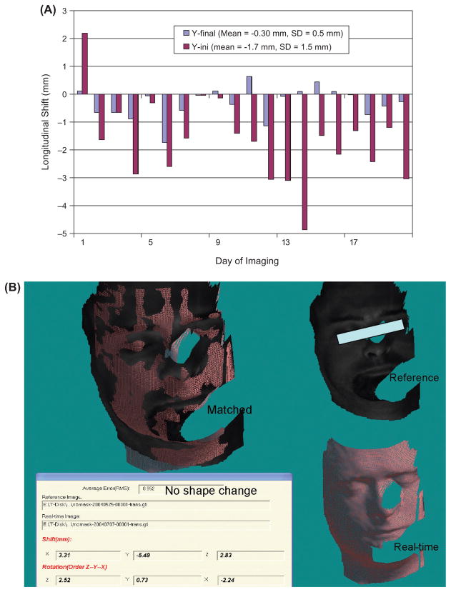
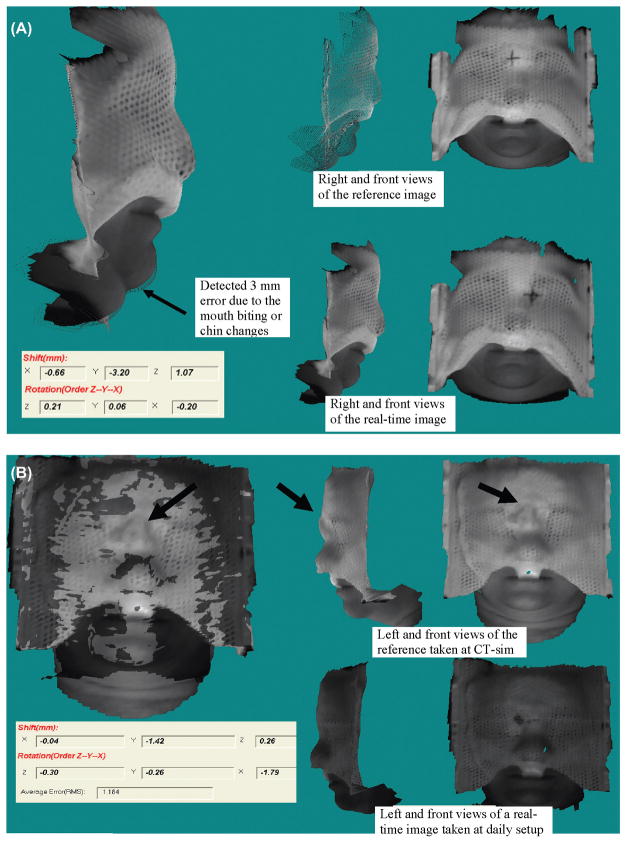
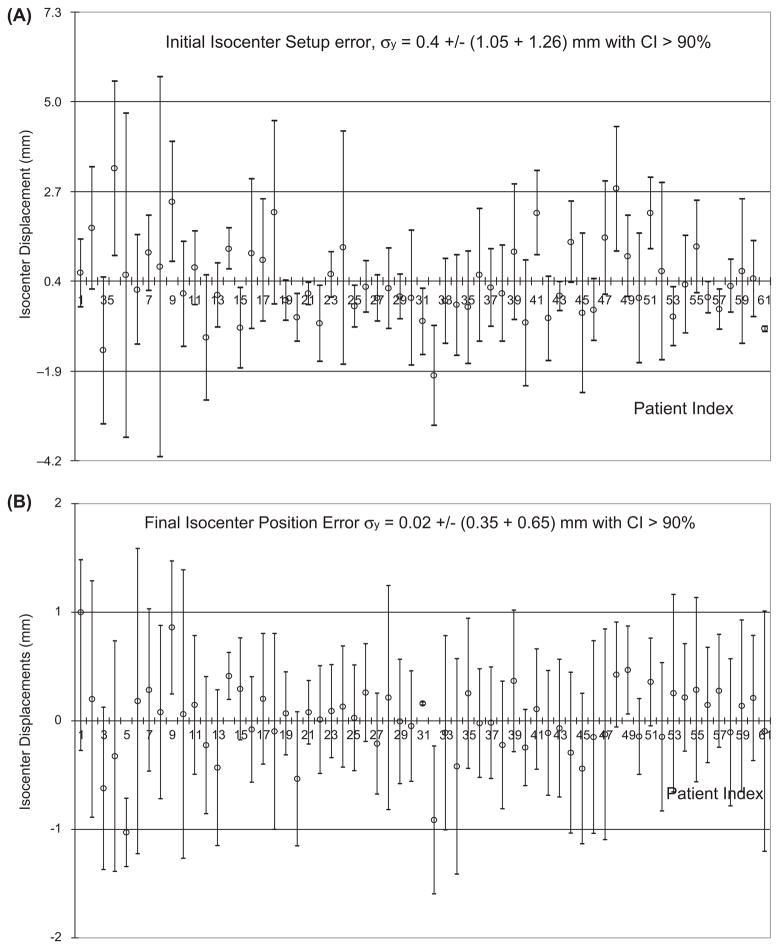
The effect of weight loss on surface guidance is not found to be significant except for one patient, who undertook several weeks of IMRT, had significant weight loss, and required a second CT simulation. The stereovision-guidance is adjusted according to the new CT-based treatment plan for the patient. Stereovisions of patients after removal of the frontal masks were taken for checking atrophy changes. Figure 5 illustrates such measurement of another IMRT patient who has the increase in initial setup errors after the second week. Patients who wear loosing masks were also associated with large initial setup errors. Mask changes and mouth motion are common sources of errors among all patients. Figure 6 illustrates the effects of mouth opening for a patient in Figure 6(A) and facemask modification of another patient in Figure 6(B) - which although unobvious to the human eye, are easily revealed with the stereovision-guidance. Another common source of error involves the table drifting at different angles that could be easily corrected with images as shown in Figure 3. Cases 4, 9, 18, 32, 41, 48, and 51 in Figure 7 have the mean isocenter displacements of >2 mm at the initial setup that mostly due to patient motion and mask changes.
Figure 5.
Measured the displacement (Y-direction) trends versus treatment fractions for a patient (A) “(A) Measured longitudinal shifts in individual fractions and (B) an example of unstable head fixation in a initial setup for the patient detected with stereovision of his head with the frontal mask removed”.
Figure 6.
(A) Effect of mouth movement on the stereovision-guidance discovered in an earlier case 4 that is hardly recognized without comparison of the 3D surface changes (arrow pointed), (B) A sharp bridge of SM on the patient nose shown in the bright reference image was smoothed out at the second day because it hurt patient. This caused an isocenter translation (>1 mm) and head rotation (>1 degree) at the daily initial setup (dark surface) for the 32nd patient.
Figure 7.
Measured isocenter displacements along the Y-axis for the 61 patients wearing RM at the initial setup with error σy = 0.4 ± 2.3 mm (A) and at the final position with error σy = 0.0 ± 1.0 mm (B).
Accuracy, Precision, and Efficiency
User influence on the accuracy and precision is not accounted for by the stereovision-guided head refixation because image registration is automatic. There are a total of fifteen therapists and physicists who utilize the system. Results of the real-time images and on-line adjustments are stored in the patient database. Figure 7 shows that the largest initial isocenter displacement of 0.4 ± 2.3 mm along the longitudinal direction (Y-axis) is significantly reduced to 0.0 ± 1.0 mm at the final positions for the 61 patients wearing SMs. The systematic errors are corrected under real-time surface-guidance so that the mean value of the isocenter displacement at the final position can be <1.1 mm.
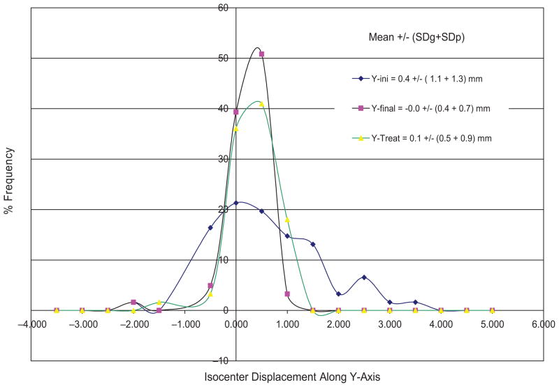
Figure 8 plots the isocenter displacement distribution along the Y-axis at the initial setup, final position, and during beam-on time for the 61 FSR patients wearing SM. Similar plots are obtained for other directions but less spread out. The accuracy and precision of isocenter displacements and rotation displacements is summarized in Table II. The image-guided head refixation has significantly improved the isocenter position from 0.4 ± 2.3 mm to 0.0 ± 1.0 mm in the longitudinal direction with the measured confidence interval of ~90% (e.g. only one out of ten days having setup error ≥1 mm). The angular improvement is not significant since we did not make small angle (<1 degree) corrections. The isocenter precision at the treatment is a little worse (1.3 mm) than that of the final positions (1.0 mm) due to the table drifts after rotation.
Figure 8.
Distributions of isocenter displacements along the Y-axis for RM group of 61 patients. The standard deviations for individual patients were also included in the precision calculation but not shown in the plots.
Table II.
Accuracy and precision for the initial setup (initial), final position (final), and during the treatment (treat) for the groups of patients wearing RM and FM using the real-time surface images.
| Methods
|
Isocenter Translation Displacement
|
Head Rotation Displacement
|
|||||
|---|---|---|---|---|---|---|---|
| Mask | at | X (mm) | Y (mm) | Z (mm) | ωx (degree) | ωy (degree) | ωz (degree) |
| RM | Initial | 0.05 ± 1.04 | 0.40 ± 2.31 | −0.15 ± 1.59 | −0.04 ± 0.73 | 0.01 ± 0.29 | −0.08 ± 0.76 |
| Final | −0.03 ± 0.74 | 0.02 ± 1.00 | 0.08 ± 0.86 | −0.00 ± 0.72 | 0.02 ± 0.30 | −0.02 ± 0.98 | |
| Treat | −0.01 ± 1.08 | −0.09 ± 1.32 | v0.08 ± 0.84 | −0.02 ± 0.55 | 0.04 ± 0.45 | v0.01 ± 0.75 | |
| FM | Initial | −0.80 ± 2.84 | −0.35 ± 2.72 | 0.76 ± 4.27 | −0.25 ± 1.74 | 1.26 ± 1.54 | −0.19 ± 2.24 |
| Final | −0.78 ± 2.82 | 0.56 ± 2.48 | −0.37 ± 1.70 | −0.34 ± 1.61 | −0.29 ± 1.33 | −0.02 ± 1.44 | |
| Treat | −0.19 ± 1.65 | 0.38 ± 1.56 | −0.03 ± 1.05 | −0.14 ± 1.17 | −0.11 ± 0.91 | −0.20 ± 1.79 | |
For patients wearing the FMs, the largest correction is in the anterior-posterior direction with precision improved from 4.3 mm to 1.7 mm. The large uncertainty in the anterior-posterior direction mainly came from the non-rigid attachment of the extended board for the head-mask. There is no improvement in the other directions. Head positioning for patients wearing FMs was affected by patient respiration and body motion. Passive and active patient motion against a small adjustment increases position errors in horizontal plane. Such variations have been reduced during the treatments when there is less patient interruption. The large errors (>4 mm) in the earlier cases are actually reduced to ~1.5 mm in the later four cases for the patients wearing the FMs indicating a possible effect of the learning curve on making adjustments of the patient’s head inside the FM.
Dosimetric Improvement
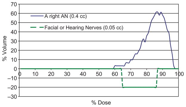
When a large movement is detected during irradiation, the beam is stopped and head position is corrected and verified with stereovision guidance. These improve the delivered dose on tumor coverage and avoid creation of hot spots to the nearby critical structures. Subtracted DVHs between the plans with daily initial setup and final positions under stereo-vision guidance in Figure 9 illustrates the significant target coverage increases of > 30% and hotspot dose and volume decreases of ~ 20% for a patient with a typical-size (1-cm) acoustic neuroma wearing a SM.
Figure 9.
Significant improvement on tumor coverage and hotspot dose reduction shown on the subtracted DVHs, DVHs at treatment position - DVHs at the initial setup, for a right acoustic neuroma and its periphery hearing or facial nerves. Measured isocenter shifts in the five treatment sessions were included in the DVHs calculation for the composite plans.
On average, the stereovision-guided head refixation takes a few seconds for the imaging and registration. Compared to the radiograph or Cone-Beam CT verification (available now), stereovision-guided head refixation proves to be far more efficient. We have frequently taken images to verify patient head positions when the radiation beam/arc is on. There are no interruption of the treatment while capturing images and checking target position, and no ionization risks for the stereovision-guidance. Thus, it is also safer than radiographic verification. Some patients may feel uncomfortable under the flashing lights from surface imaging, but that is easily remedied by having them close their eyes during the treatment. There are virtually no adverse side effects discovered throughout the entire clinical trial.
Existing clinical studies have shown that mask-based head refixation with errors of 2–3 mm can be significantly improved by integrating an additional fixation (39, 40). The BrainLAB Novalis system has also recently included an “ExacTrac” image-guided technique for target positioning. The new technique “exactly” matches the DRRs from the planning CT-images with the biplane kV radiographs and optically “tracks” the table movement using a few infrared markers. Assuming no patient motion after the image verification, this image-guided head refixation could achieve sub-millimeter position accuracy (28, 41). In order to measure not only the inter-fractional setup errors but also intra-fractional patient motion during individual beams or arcs, we have first introduced the real-time stereovision (3D optical surface) guided technique for FSR (33). It has been first applied on 70 patients wearing relatively rigid SM or flexible FM. Our clinical results show that 1 mm and 1.5 mm precision can be clinically achieved on patients with SM and on patients with FM, respectively. There are no additional devices, contacts, markings, ionization risks, or treatment interruptions for position verification prior to and during delivery of individual beams or arcs.
The major limitation for stereovision guidance is the lack of information for the internal structures. Volume imaging, such as cone-beam CT or tomography, would be helpful for internal target verification. The mask-based stereotactic head refixation using daily CT (17) or CBCT images (42) determined large iso-center shifts of > 2 mm in the longitudinal direction on patients wearing SMs that agreed with our measured results for initial setup errors of 2–3 mm for the 61 patients wearing SMs. The repositioning accuracy could actually be improved to ~1 mm by using the real-time stereovision guidance shown in the final positions and during the treatments. Integrating volumetric CT images and the real-time surface images could be a solution to achieve an efficient and accurate target repositioning.
There are several optical-tracking systems for head positioning. The famous Florida University technique (24–27) uses infrared cameras to measure the head position by tracking the images of the infrared reflected markers. The accuracy of this system is limited by the precision and accuracy of markers attached to the patient’s head. A photogrammetric technique initially introduced by the German Cancer Research Center (28) utilized bite block landmarks. Another important work (43, 44) from the University of Chicago uses two video cameras mounted to the walls and ceiling of the treatment room. Images from the two cameras on the first day are saved as the reference images. Comparing live video images with the reference images using a subtraction, users can interactively move the patient to produce a null image, and, thus, reproduce the previous position. Its use has facilitated a reduction in large patient repositioning errors but failed to achieve the accuracy and precision necessary for FSR.
A real-time 3D-optical surface-guided system, AlignRT system, has been recently commercialized by Vision-RT (Vision-RT Inc. London, UK) (45). This system has been successfully tested in a smooth-surface partial breast irradiation trial. The major difference between Vision-RT and our systems is that AlignRT system uses white speckle lights to reconstruct surface-mesh having reasonable spatial resolution of 2–5 mm while our system uses rainbow lights to reconstruct surface from individual image pixels having high resolution of 0.2 to 0.5 mm. Another major advantage of the rainbow camera is analytic solution for 3D surface point reconstruction (34) Having spatial resolution of 0.5 mm at the focus distance of 184 cm for reconstructing every pixel of video image matrix of 680 × 480, our imaging system can detect more detail surface shape and location required for stereovision guidance. By increase image matrix with updated desk-top computer, the resolution could be doubled. The real-time stereovision-guidance applied to all FSR patients under the clinical trial has achieved an accuracy and precision comparable to traditional frame-based setup while remaining vastly less invasive and uncomfortable. This stereovision-guided FSR proves to be more efficient by allowing for fewer interruptions for position verification prior to or during the irradiation. It is also safer than the X-ray-image-based head refixation. Most importantly, it is capable to verify the head position during the beam-on time. For future development of image-guided techniques, it is interesting to combine the stereovision and cone-beam-CT images to unfold the head surface relation to the intracranial target.
Conclusions
This first clinical trial on optical surface guided FSR and IMRT has accrued sixty-one FSR patients wearing stereotactic masks (SMs) and nine IMRT patients wearing flexible masks (FMs). The clinical results validate that the accuracy ± precision in direction with the largest errors has been improved from 0.4 ± 2.3 mm to 0.0 ± 1.0 in the inferior-to-superior direction for patients wearing SM or from 0.8 ± 4.3 mm to 0.4 ± 1.7 mm in the posterior-to-anterior direction for patients wearing FM. The differences among the three directions for different masks are associated with the uncertainties of the masks and head supporting devices that is first in-vivo quantified with the stereovision-guidance. Importantly, the system may lead us toward head position check during beam-on time and having frameless head refixation.
Acknowledgments
This research was initially supported by a Pilot Grant at Johns Hopkins and then a SBIR Phase I grant from NIH.
Authors greatly appreciate the support in part by an Alexander and Margaret Stewart Trust grant at Johns Hopkins Cancer Center (2000) and a NCI SBIR Phase I grant 1R43CA91690-01 (2003). We want to thank many patients, therapists, residents, physicists, and physicians at Johns Hopkins University and technical persons from Genex Technology Inc. in Maryland to support and participate in this pilot study.
Footnotes
Conflicts of Interest
There is no financial conflict of interest for any of these authors.
References
- 1.Winston KR, Lutz W. Linear accelerator as a neurosurgical tool for stereotactic radiosurgery. Neurosurgery. 1988;22:454–464. doi: 10.1227/00006123-198803000-00002. [DOI] [PubMed] [Google Scholar]
- 2.Lyman JT, Phillips MH, Frankel KA, Fabrikant JI. Stereotactic frame for neuroradiology and charged particle Bragg peak radiosurgery of intracranial disorders. Int J Radiat Oncol Biol Phys. 1989;16:1615–1621. doi: 10.1016/0360-3016(89)90971-1. [DOI] [PubMed] [Google Scholar]
- 3.Mack A, Czempiel H, Kreiner HJ, Dürr G, Wowra B. Quality assurance in stereotactic space. A system test for verifying the accuracy of aim in radiosurgery. Med Phys. 2002;29:561–568. doi: 10.1118/1.1463062. [DOI] [PubMed] [Google Scholar]
- 4.Choi DR, Ahn YC, Kim DY, Huh SJ, Lee JI. Accuracy in target localization in stereotactic radiosurgery. Med Dosim. 1997;22:53–58. doi: 10.1016/s0958-3947(96)00151-3. [DOI] [PubMed] [Google Scholar]
- 5.Yeung D, Palta J, Fontanesi J, Kun L. Systematic analysis of errors in target localization and treatment delivery in stereotactic radiosurgery (SRS) Int J Radiat Oncol Biol Phys. 1994;28:493–498. doi: 10.1016/0360-3016(94)90076-0. [DOI] [PubMed] [Google Scholar]
- 6.Hartmann GH, Bauer-Kirpes B, Serago CF, Lorenz WJ. Precision and accuracy of stereotactic convergent beam irradiations from a linear accelerator. Int J Radiat Oncol Biol Phys. 1994;28:481–492. doi: 10.1016/0360-3016(94)90075-2. [DOI] [PubMed] [Google Scholar]
- 7.Serago CF, Lewin AA, Houdek PV, Gonzalez-Arias S, Schwade JG, Abitbol A, Marcial-Vega V. Radiosurgery target point alignment errors detected with portal film verification. Int J Radiat Oncol Biol Phys. 1992;24:777–780. doi: 10.1016/0360-3016(92)90728-z. [DOI] [PubMed] [Google Scholar]
- 8.Phillips MH, Frankel KA, Lyman JT, Fabrikant JI, Levy RP. Heavy charged-particle stereotactic radiosurgery: cerebral angiography and CT in the treatment of intracranial vascular malformations. Int J Radiat Oncol Biol Phys. 1989;17:419–426. doi: 10.1016/0360-3016(89)90460-4. [DOI] [PubMed] [Google Scholar]
- 9.Schell MC, Bova FJ, Larson DA, Leaviu DD, Lutz WR, Podgorsak EB, Wu A. AAPM Report No. 54: Stereotactic Radiosurgery. American Institute of Physics; Woodbury, NY: 1995. [Google Scholar]
- 10.Muller K, Nowak PJ, Luyten GP, Marijnissen JP, de Pan C, Levendag P. A modified relocatable stereotactic frame for irradiation of eye melanoma: design and evaluation of treatment accuracy. Int J Radiat Oncol Biol Phys. 2004;58:284–291. doi: 10.1016/j.ijrobp.2003.08.029. [DOI] [PubMed] [Google Scholar]
- 11.Burton KE, Thomas SJ, Whitney D, Routsis DS, Benson RJ, Burnet NG. Accuracy of a relocatable stereotactic radiotherapy head frame evaluated by use of a depth helmet. Clin Oncol (R Coll Radiol) 2002;14:31–39. doi: 10.1053/clon.2001.0001. [DOI] [PubMed] [Google Scholar]
- 12.Salter BJ, Fuss M, Vollmer DG, Sadeghi A, Bogaev CA, Cheek DA, Herman TS, Hevezi JM. The TALON removable head frame system for stereotactic radiosurgery/radiotherapy: measurement of the repositioning accuracy. Int J Radiat Oncol Biol Phys. 2001;51:555–562. doi: 10.1016/s0360-3016(01)01670-4. [DOI] [PubMed] [Google Scholar]
- 13.Kooy HM, Dunbar SF, Tarbell NJ, Mannarino E, Ferarro N, Shusterman S, Bellerive M, Finn L, McDonough CV, Loeffler JS. Adaptation and verification of the relocatable Gill-Thomas-Cosman frame in stereotactic radiotherapy. Int J Radiat Oncol Biol Phys. 1994;30:685–691. doi: 10.1016/0360-3016(92)90956-i. [DOI] [PubMed] [Google Scholar]
- 14.Laing RW, Thompson V, Warrington AP, Brada M. Feasibility of patient immobilization for conventional cranial irradiation with a relocatable stereotactic frame. Br J Radiol. 1993;66:1020–1024. doi: 10.1259/0007-1285-66-791-1020. [DOI] [PubMed] [Google Scholar]
- 15.Takahashi T, Nishimura K, Hondo M, Okada T, Osada H, Honda N. Measurement of repositioning accuracy during fractionated stereotactic radiotherapy for intracranial tumors using noninvasive fixation of BrainLAB radiotherapy equipment. Int J Radiat Oncol Biol Phys. 2006;66:S67–70. [Google Scholar]
- 16.Georg D, Bogner J, Dieckmann K, Pötter R. Is mask-based stereotactic head-and-neck fixation as precise as stereotactic head fixation for precision radiotherapy? Int J Radiat Oncol Biol Phys. 2006;66:S61–66. [Google Scholar]
- 17.Takeuchi H, Yoshida M, Kubota T, Ishii H, Sato K, Handa Y, Itoh H. Frameless stereotactic radiosurgery with mobile CT, mask immobilization and micro-multileaf collimators. Minim Invasive Neurosurg. 2003;46:82–85. doi: 10.1055/s-2003-39342. [DOI] [PubMed] [Google Scholar]
- 18.Karger CP, Jakel O, Debus J, Kuhn S, Hartmann GH. Three-dimensional accuracy and interfractional reproducibility of patient fixation and positioning using a stereotactic head mask system. Int J Radiat Oncol Biol Phys. 2001;49:1493–1504. doi: 10.1016/s0360-3016(00)01562-5. [DOI] [PubMed] [Google Scholar]
- 19.Hamilton RJ, Kuchnir FT, Pelizzari CA, Sweeney PJ, Rubin SJ. Repositioning accuracy of a noninvasive head fixation system for stereotactic radiotherapy. Med Phys. 1996;23:1909–1917. doi: 10.1118/1.597754. [DOI] [PubMed] [Google Scholar]
- 20.Rosenthal SJ, Gall KP, Jackson M, Thornton AF., Jr A precision cranial immobilization system for conformal stereotactic fractionated radiation therapy. Int J Radiat Oncol Biol Phys. 1995;33:1239–1245. doi: 10.1016/0360-3016(95)02009-8. [DOI] [PubMed] [Google Scholar]
- 21.Chang SD, Main W, Martin DP, Gibbs IC, Heilbrun MP. An analysis of the accuracy of the CyberKnife: a robotic frameless stereotactic radiosurgical system. Neurosurgery. 2003;52:140–146. doi: 10.1097/00006123-200301000-00018. discussion 146–147. [DOI] [PubMed] [Google Scholar]
- 22.Murphy MJ. An automatic six-degree-of-freedom image registration algorithm for image-guided frameless stereotaxic radiosurgery. Med Phys. 1997;24:857–866. doi: 10.1118/1.598005. [DOI] [PubMed] [Google Scholar]
- 23.Adler JR, Jr, Chang SD, Murphy MJ, Hancock SL. The Cyberknife: a frameless robotic system for radiosurgery. Stereotact Funct Neurosurg. 1997;69:124–128. doi: 10.1159/000099863. [DOI] [PubMed] [Google Scholar]
- 24.Meeks SL, Bova FJ, Wagner TH, Buatti JM, Friedman WA, Foote KD. Image localization for frameless stereotactic radiotherapy. Int J Radiat Oncol Biol Phys. 2000;46:1291–1299. doi: 10.1016/s0360-3016(99)00536-2. [DOI] [PubMed] [Google Scholar]
- 25.Bova FJ, Buatti JM, Friedman WA, Mendenhall WM, Yang CC, Liu C. The University of Florida frameless high-precision stereotactic radiotherapy system. Int J Radiat Oncol Biol Phys. 1997;38:875–882. doi: 10.1016/s0360-3016(97)00055-2. [DOI] [PubMed] [Google Scholar]
- 26.Bova FJ, Meeks SL, Friedman WA, Buatti JM. Optic-guided stereotactic radiotherapy. Med Dosim. 1998;23:221–228. doi: 10.1016/s0958-3947(98)00017-x. [DOI] [PubMed] [Google Scholar]
- 27.Meeks SL, Bova FJ, Friedman WA, Buatti JM, Moore RD, Mendenhall WM. IRLED-based patient localization for linac radiosurgery. Int J Radiat Oncol Biol Phys. 1998;41:433–439. doi: 10.1016/s0360-3016(98)00040-6. [DOI] [PubMed] [Google Scholar]
- 28.Menke M, Hirschfeld F, Mack T, Pastyr O, Sturm V, Schlegel W. Photogrammetric accuracy measurements of head holder systems used for fractionated radiotherapy. Int J Radiat Oncol Biol Phys. 1994;29:1147–1155. doi: 10.1016/0360-3016(94)90412-x. [DOI] [PubMed] [Google Scholar]
- 29.Jin JY, Ryu S, Faber K, Mikkelsen T, Chen Q, Li S, Movsas B. 2D/3D Image Fusion for Accurate Target Localization and Evaluation of a Mask Based Stereotactic System in Fractionated Stereotactic Radiotherapy of Cranial Lesions. Med Phys. 2006;33:2780–2785. doi: 10.1118/1.2392605. [DOI] [PubMed] [Google Scholar]
- 30.Ryu S, Khan M, Yin FF, Concus A, Ajlouni M, Benninger MS, Kim JH. Image-guided radiosurgery of head and neck cancers. Otolaryngol Head Neck Surg. 2004;130:690–697. doi: 10.1016/j.otohns.2003.10.009. [DOI] [PubMed] [Google Scholar]
- 31.Li S, Jackson JF, Myers LT, Detorie NA, Dicello JF. A simple and accurate coordinate transformation for a stereotactic radiotherapy system. Med Phys. 1999;26:518–523. doi: 10.1118/1.598551. [DOI] [PubMed] [Google Scholar]
- 32.Li S, Williams J, Wharams M, Jackson J, Myers L, Detorie N, Dicello J. Coordinate transformation and positioning uncertainties for fractionated stereotactic radiation therapy. Radiology. 1998;209(P):397. (Abs) [Google Scholar]
- 33.Li S, Geng J, Williams J, Chen G. A novel 3D-video-based refixation technique for fractionated stereotactic radiotherapy. Medical Physics. 2000;27:1433. (abs) [Google Scholar]
- 34.Li S, Liu D, Yin G, Zhuang P, Geng J. Real-time 3D-surface-guided head refixation useful for fractionated stereotactic radiotherapy. Med Phys. 2006;33:492–503. doi: 10.1118/1.2150778. [DOI] [PubMed] [Google Scholar]
- 35.Li S, Geng J, Liu D, Rigamonti D, Kleinberg L, He S, DeWeese T. Automatic Detection Of Head Refixation Errors In Fractionated Stereotactic Radiotherapy (FSR). IEEE International Symposium on Biomedical Imaging. IEEE International Symposium on Biomedical Imaging; Arlington, VA, USA. 2004. pp. 284–287. [Google Scholar]
- 36.Djajaputra D, Li S. Real-time 3D surface-image-guided beam setup in radiotherapy of breast cancer. Med Phys. 2005;32:65–75. doi: 10.1118/1.1828251. [DOI] [PubMed] [Google Scholar]
- 37.Liu D, Li S. Accurate calibration of a stereo-vision system in image-guided radiotherapy. Med Phys. 2006;33:4379–4383. doi: 10.1118/1.2362873. [DOI] [PubMed] [Google Scholar]
- 38.Use of computers in external beam radiotherapy procedures with high-energy photons and electrons: International Commission on Radiation Units and Measurements. Bethesda, MD: 1987. ICRU_Report_42. [Google Scholar]
- 39.Baumert BG, Egli P, Studer S, Dehing C, Davis JB. Repositioning accuracy of fractionated stereotactic irradiation: assessment of isocentre alignment for different dental fixations by using sequential CT scanning. Radiother Oncol. 2005;74:61–66. doi: 10.1016/j.radonc.2004.08.002. [DOI] [PubMed] [Google Scholar]
- 40.Lopatta E, Liesenfeld SM, Bank P, Wurm R, Günther R, Wiezorek T, Wendt TG. Improved patient repositioning accuracy by integrating an additional jaw fixation into a high precision face mask system in stereotactic radiotherapy of the head. Strahlenther Onkol. 2003;179:571–575. doi: 10.1007/s00066-003-0941-3. [DOI] [PubMed] [Google Scholar]
- 41.Yan H, Yin FF, Kim JH. A phantom study on the positioning accuracy of the Novalis Body system. Med Phys. 2003;30:3052–3060. doi: 10.1118/1.1626122. [DOI] [PubMed] [Google Scholar]
- 42.Boda-Heggemann J, Walter C, Rahn A, Wertz H, Loeb I, Lohr F, Wenz F. Repositioning accuracy of two different mask systems -3D revisited: comparison using true 3D/3D matching with cone-beam CT. Int J Radiat Oncol Biol Phys. 2006;66:1568–1575. doi: 10.1016/j.ijrobp.2006.08.054. [DOI] [PubMed] [Google Scholar]
- 43.Milliken BD, Rubin SJ, Hamilton RJ, Johnson LS, Chen GT. Performance of a video-image-subtraction-based patient positioning system. Int J Radiat Oncol Biol Phys. 1997;38:855–866. doi: 10.1016/s0360-3016(97)00081-3. [DOI] [PubMed] [Google Scholar]
- 44.Johnson LS, Milliken BD, Hadley SW, Pelizzari CA, Haraf DJ, Chen GT. Initial clinical experience with a video-based patient positioning system. Int J Radiat Oncol Biol Phys. 1999;45:205–213. doi: 10.1016/s0360-3016(99)00182-0. [DOI] [PubMed] [Google Scholar]
- 45.Bert C, Metheany KG, Doppke K, Chen GT. A phantom evaluation of a stereo-vision surface imaging system for radiotherapy patient setup. Med Phys. 2005;32:2753–2762. doi: 10.1118/1.1984263. [DOI] [PubMed] [Google Scholar]


