Abstract
Magnetic Resonance Imaging (MRI) has potential to be a superior medical imaging modality for guiding and monitoring prostatic interventions. The strong magnetic field prevents the use of conventional mechatronics and the confined physical space makes it extremely challenging to access the patient. We have designed a robotic assistant system that overcomes these difficulties and promises safe and reliable intra-prostatic needle placement inside closed high-field MRI scanners. The robot performs needle insertion under real-time 3T MR image guidance; workspace requirements, MR compatibility, and workflow have been evaluated on phantoms. The paper explains the robot mechanism and controller design and presents results of preliminary evaluation of the system.
I. Introduction
Each year approximately 1.5M core needle biopsies are performed, yielding about 220,000 new prostate cancer cases in the U.S. [1]. If the cancer is confined to the prostate, then low-dose-rate (LDR) permanent brachytherapy is a common treatment option; a large number (50-150) of radioactive pellets/seeds are implanted into the prostate using 15–20cm long 18G needles [2]. A complex seed distribution pattern must be achieved with great accuracy in order to eradicate the cancer, while minimizing radiation toxicity to adjacent healthy tissues. Transrectal Ultrasound (TRUS) is the current “gold standard” for guiding both biopsy and brachytherapy; however, TRUS-guided biopsy has a detection rate of only 20–30% [3]. Furthermore, TRUS cannot effectively monitor the implant procedure as implanted seeds cannot be seen in the image. MRI seems to possess many of the capabilities that TRUS is lacking with high sensitivity for detecting prostate tumors, high spatial resolution, excellent soft tissue contrast, and volumetric imaging capabilities. However, closed-bore high-field MRI has not been widely adopted for prostate interventions because strong magnetic fields and confined physical space present formidable challenges.
The clinical efficacy of MRI-guided prostate brachytherapy and biopsy was demonstrated by D'Amico, Tempany, et al. at the Brigham and Women's Hospital using a 0.5T open-MRI scanner [4]. The needles were inserted manually using a guide comprising a grid of holes, with the patient in the lithotomy position, similarly to the TRUS-guided approach. Zangos et al. used a transgluteal approach with 0.2T MRI, but did not specifically target the tumor foci [5]. Susil et al. described four cases of transperineal prostate biopsy in a closed-bore scanner, where the patient was moved out of the bore for needle insertions and then placed back into the bore to confirm satisfactory placement [6]. Beyersdorff et al. performed targeted transrectal biopsy in a 1.5T MRI unit with a passive articulated needle-guide and have reported 12 cases of biopsy to date [7]. Robotic assistance has been investigated for guiding instrument placement in MRI, beginning with neurosurgery [8] and later percutaneous interventions [9], [10]. Chinzei et al. developed a general-purpose robotic assistant for open MRI [11] that was subsequently adapted for transperineal intra-prostatic needle placement [12]. Krieger et al. presented a 2-DOF passive, un-encoded and manually manipulated mechanical linkage to aim a needle guide for transrectal prostate biopsy with MRI guidance [13]. With the use of three active tracking coils, the device is visually servoed into position and then the patient is moved out of the scanner for needle insertion. Stoianovici et al. has made developments in pneumatic stepper motors and applied them toward robotic brachytherapy seed placement thus far demonstrated in training phantoms [14]. Other recent developments in MRI-compatible mechanisms include pneumatic stepping motors on a light needle puncture robot [15] and haptic interfaces for fMRI [16].
This work introduces the design of a novel computer-integrated robotic mechanism for transperineal prostate needle placement in 3T closed-bore MRI. The mechanism is capable of positioning the needle for treatment by ejecting radioactive seeds or diagnosis by harvesting tissue samples inside the magnet bore, under remote control of the physician without moving the patient out of the imaging space. This enables the use of real-time multi-parametric imaging for precise placement of needles in soft tissues. In addition to structural images, protocols for diffusion imaging and MR spectroscopy will be available intraoperatively, promising enhanced visualization and targeting of pathologies. Accurate and robust needle placement devices, navigated based on such image guidance, are becoming valuable clinical tools and have clear applications in several other organ systems.
An overview of the full system architecture, including details regarding planning software and integration of real-time MR imaging isdescribed in [17]. This paper focusses on design and evaluation of the robotic needle placement manipulator and is organized as follows: Section II describes the design requirements for the proposed device, Section III outlines details of system prototype design. Results of preliminary evaluation are presented in Section IV, with conclusions discussed in Section V.
II. Design Requirements
A. Workspace Analysis
The system's primary function is to accurately place needles in the prostate for the purpose of biopsy and brachytherapy seed placement. In our approach, the patient is positioned in the supine position with the legs spread and raised as shown in Fig. 1 (left). The patient is positioned in a similar configuration to TRUS-guided brachytherapy, but the MRI bore's constraint (60cm diameter) requires that the legs be spread less and the knees be lower into a semi-lithotmy position. The robot operates in the confined space between the patient's legs without interference with the patient, MRI scanner components, anesthesia equipment, and auxiliary equipment present as shown in the cross-section shown in Fig. 1 (right).
Fig. 1.
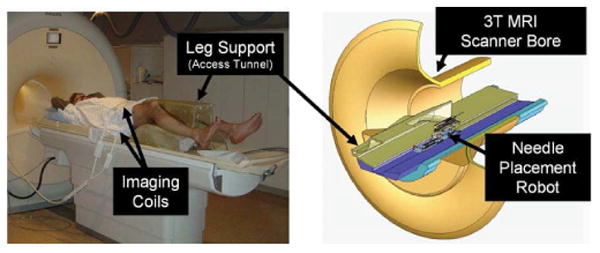
Patient positioning on the leg support (left) and robot positioning within the confined space of the access tunnel (right). The robot accesses the patient's prostate through the perineal wall which rests against an opening in the superior surface of the leg rest.
The average size of the prostate is 50mm in the lateral direction by 35mm in the anterior-posterior direction by 40mm in length. The prostate volume can be approximated by an elliptical volume formula of the form V = (.525 × D1 × D2 × D3), and the average volume is about 35cc. Due to swelling, the volume of the prostate can also enlarge by 25% by the end of the procedure [18]. The standard 60mm × 60mm perineal window of TRUS-guided brachytherapy was increased to 100mm × 100mm, in order to accommodate patient variability and lateral asymmetries in patient setup. In depth, the workspace is extends to 150mm superior of the perineal surface. Direct access to all clinically relevant locations in the prostate is not always possible with a needle inserted purely along apex-base direction due to pubic arch interference (PAI). If more than 25% of the prostate diameter is blocked (typically in prostates larger than 55cc), then the patient is usually declined for implantation [18]. The addition of rotational alignment in the sagittal and coronal planes in the proposed system will enable the procedure to be performed on many of these patients who are usually contraindicated for brachytherapy due to PAI.
B. System Requirements
The workspace analysis allows us to derive kinematic requirements for the robot. A kinematic diagram is shown in Fig. 2; the primary motions of the base include two prismatic motions and two rotational motions upon a manual linear slide. The slide positions the robot in the access tunnel and allows fast removal for reloading brachytherapy needles or collecting harvested biopsy tissue. In addition to these base motions, application-specific motions are also required; these include needle insertion, canula retraction, needle rotation, and biopsy gun actuation. The accuracy of the individual servo controlled joints is targeted to be 0.1mm, and the needle placement accuracy of the robot is targeted to be 0.5mm. The overall system accuracy, however, is expected to be somewhat less when effects such as imaging resolution, needle deflection, and tissue deformation are taken into account. The specifications for the requirements of each motion are shown in Table I. The numbered motions in the table correspond to the labeled joints in the equivalent kinematic diagram shown in Fig. 2. These specifications represent a flexible system that can accommodate a large variety of patients.
Fig. 2.
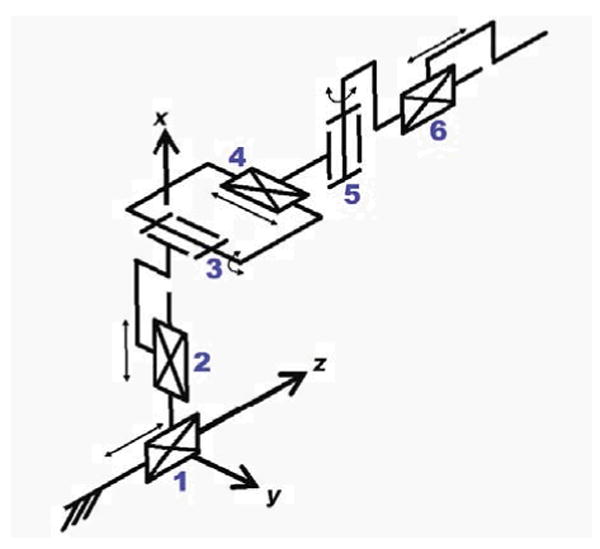
Equivalent kinematic diagram of the robot -details the primary six degrees of freedom for needle insertion procedures with this manipulator. Additional application-specific end effectors may be added to provide additional DOF.
Table I. Kinematic Specifications.
| Degree of freedom | Motion | Requirements | |
|---|---|---|---|
| 1) | Gross Axial Position | 1m | Manual with repeatable stop |
| 2) | Vertical Motion | 0-100mm | Precise servo control |
| 3) | Elevation Angle | +15°, −0° | Precise servo control |
| 4) | Horizontal Motion | ±50mm | Precise servo control |
| 5) | Azimuth Angle | ±15° | Precise servo control |
| 6) | Needle Insertion | 150mm | Manual or Automated |
| 7) | Canula Retraction or Biopsy Gun Firing | 60mm | Manual or Automated |
| 8) | Needle Rotation | 360° | Manual or Automated |
C. MRI Compatibility Requirements
Design of a system operating inside the bore of a high-field 1.5-3T MRI scanner adds significant complexity since standard materials, sensors and actuators cannot be employed. In order for a device to be MR compatible, it must be MR safe and not compromise image quality. Both issues relate to the use of metals and electronics, in three respects. First, ferromagnetic materials must be avoided because they cause image artifacts and distortion, and can become dangerous projectiles. Non-ferromagnetic metals such as aluminum, brass, and titanium or high strength plastic and composite materials are therefore permissible. Second, we must prevent or limit local heating in the proximity of the patient's body. Thus the materials and structures used must be either non-conductive or free of loops and of carefully chosen lengths to avoid eddy currents and resonance. Third, we must maintain image quality, by limiting the use of conductive materials in the vicinity of the scanner's isocenter. The following section details material and component selection, with the consideration of MRI compatibility issues.
III. System and Component Design
A. Overview
For the initial proof-of-concept system and Phase-1 clinical trials, it is not necessary to have all of the DOF listed in Table I. The first embodiment of the system provides the two prismatic motions in the axial (transverse) plane over the perineum (DOF#2 and DOF#4) and an encoded manual needle guide (DOF#6) representing an automated high-resolution needle guide, functionally similar to the template in conventional brachytherapy. The next design iteration will produce a 4-DOF robot base with the links made out of high strength, dimensionally stable, highly electrically insulating and sterilizable plastic (e.g. Ultem or PEEK). The 4-DOF base of the manipulator design has a modular platform that allows for different end effectors to be mounted on it. The two initial end effectors will accommodate biopsy guns and brachytherapy needles. Both require an insertion phase; the former requires activating a single-acting button to engage the device and a safety lock. The latter requires an additional controlled linear motion to accommodate the cannula retraction to release the brachytherapy seeds. Sterility has been taken into consideration for the design of the end effectors. In particular, the portions of the manipulator and leg rest that come in direct contact with the patient or needle will be removable and made of materials that are suitable for sterilization. The remainder of the robot will be draped.
B. Mechanism Design
Since the robot is constructed without the use of metallic links, mechanism design is particularly important. With a proper design: the kinematics can be simplified, control can be made less complex, motions may be decoupled, actuators can be aligned appropriately and system rigidity can be increased. Based upon analysis of the workspace and the application, the following additional design requirements have been adopted:
Linear motion should be able to be decoupled from the rotations since the majority of procedures will not require the two rotational DOF.
Actuator motion should be in the axial direction (aligned with the scanner's axis, Bo) to maintain a compact profile.
Extension in both the vertical and horizontal planes should be telescopic to minimize the working envelope.
The four primary base degrees of freedom (DOF #25 in Table I) are broken into two decoupled 2-DOF planar motions. In order to maintain high rigidity, planar bar mechanisms are used. Other options include cables, pulleys, gears, linear slides, leadscrews, etc.; however, these were avoided in an attempt to design a very reliable, robust, compact, and rigid system. Motion in the vertical plane includes 100mm of vertical travel, and up to 15° of positive elevation angle. This is achieved using a modified version of a scissor lift mechanism that is traditionally used for plane parallel motion. By coupling two such mechanisms as shown in Fig. 3, the two desired DOF can be achieved. Stability is increased by using a pair of such mechanisms in the rear. For purely prismatic, both slides move in unison; angulation (θ) is generated by relative motions. To aid in decoupling, the actuator for the rear slide can be fixed to the carriage of the primary motion linear drive, thus allowing one actuator to be locked when angulation is unnecessary. As shown in Fig. 3, the push rods for the front and rear motions are coupled together to maintain only translational motion in the initial prototype.
Fig. 3.
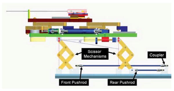
Mechanism design for motion in the vertical plane. Coupling the forward and rear motion provides for vertical travel, independently moving the rear provides for elevation angle (θ) adjustment.
Motion in the horizontal plane is accomplished with a second planar bar mechanism. This motion is achieved by coupling two straight line motion mechanisms as shown in Fig. 4, generally referred to as Scott-Russell mechanisms. By combining two such straight-line motions, both linear and rotational motions can be realized in the horizontal plane. The choice of this design over the use of the previously described scissor-type mechanism is that this allows for bilateral motion with respect to the nominal center position. Actuation is provided by a custom, MR-compatible pneumatic cylinder that is oriented in the axial direction. Fig. 4 shows the mechanism in the 1-DOF configuration where only translation is available. This is accomplished by linking the front and rear mechanisms with a coupling link. A benefit of this deign is that it is straightforward to add the rotational motion for future designs by replacing the rigid connecting bar (LC) with a pneumatic cylinder. Translational motion remains decoupled when rotation is not used by ensuring that the cylinder in the connecting bar remains locked.
Fig. 4.
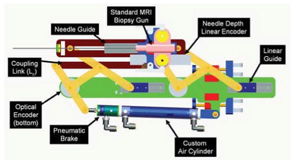
Mechanism design for motion in the horizontal plane. Provides for planar parallel motion; can provide both translation and rotation by actuating rear motion independently by replacing coupling link (LC) with a second cylinder. The attached needle guide provides accurate depth measurement during manual needle insertion. The modular needle guide can be replaced with different end effectors for other procedures.
C. Actuator Design
The MRI environment restricts the choice of sensors and actuators. Many robots use electro-dynamic actuation, however, the very nature of an electric motor precludes its use in high-field magnetic environments. Therefore, it is necessary to: 1) use actuators that are compatible with the MR environment, or 2) to use a transmission to mechanically couple the manipulator in close proximity to the scanner to standard actuators situated outside the high field. MR compatible actuators such as piezoceramic motors have been evaluated by [19] and [11]; however, these are prone to introducing noise into MR imaging and therefore negatively impacting image quality. The latter can take the form of flexible driveshafts [13], push-pull cables, or hydraulic (or pneumatic) couplings [16].
To maintain close proximity of the actuators to the robot, alternatives to electric motors include hydraulic or pneumatic actuators. Hydraulic actuators offer the advantages of high stiffness and near-incompressible flow at the expense of speed/bandwidth, more difficult fluid connections, and the potential for leaks. Pneumatic actuators offer relatively high speed, large availability of components, and readily available compressed air supply at the expense of decreased rigidity and less straightforward control due to the compressibility of air and the relatively large non-linear friction forces in the cylinder. Further, portability of the system and ease of connections contradicts the closed-system nature of hydraulic actuators. Pneumatic cylinders are the actuator of choice for this robot.
Although pneumatic actuation seems ideal for MRI, most standard pneumatic cylinders are not suitable for use in MRI. Custom MR compatible pneumatic cylinders have been developed for use with this robot. The cylinders are based upon Airpel 9.3mm bore cylinders 1. These cylinders were chosen because the cylinder bore is made of glass and the piston and seals are made of graphite. This design has two main benefits; the primary components are suitable for MRI and they inherently have very low friction (as low as 1g). In collaboration with the manufacturer, we developed the cylinders shown in Fig. 5 that are entirely nonmetallic except for the brass shaft. The cylinders can handle up to 100psi (6.9bar) and therefore can apply forces up to 46.8N.In addition to moving the robot, it is important to be able to lock it in position to provide a stable needle insertion platform. Pneumatically operated, MR compatible brakes have been developed for this purpose. The brakes are compact units that attach to the ends of the previously described cylinders as shown in Fig. 4 and clamp down on the rod. The design is such that the fail-safe state is locked and applied air pressure releases a spring-loaded collet to enable motion. The brakes are disabled when the axis is aligned and applied when the needle is to be inserted or an emergency situation arises.
Fig. 5.
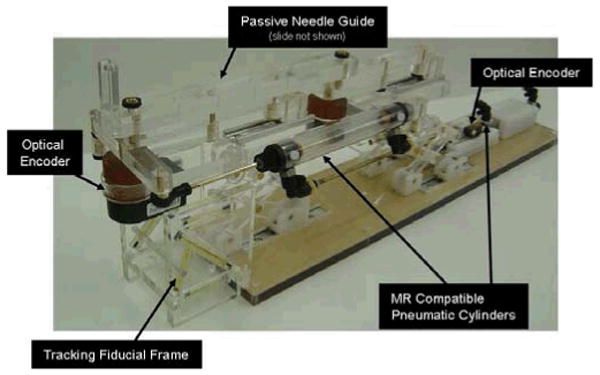
Robotic needle placement mechanism with two active DOF and one passive, encoded needle insertion. Actuation is by custom, MR compatible pneumatic cylinder and position sensing by optical encoders. Dynamic global registration is achieved with the attached tracking fiducial.
There are three basic valve types that are used for servo control of a cylinder: 1) High-bandwidth on-off valves, 2) Proportional flow spool valves, and 3)Proportional pressure regulator valves. Proportional pressure regulators were the valve of choice for this robot because they allow for direct control of the pressure, thus the force, on the robot. This is an advantage because it aids in controller design and also has the inherent safety of being able to limit applied pressure to a prescribed amount.
Most pneumatic valves are operated either directly by a solenoid coil or indirectly by a small pilot valve that is actuated by a solenoid coil. Unfortunately, as with electric motors, the very nature of a solenoid coil is a contraindication for its use in an MR environment. With pneumatic control, it is essential to limit the distance from the valve to the cylinder on the robot; thus it is important to use valves that are safe and effective in the MR environment. The robot uses piezoelectrically actuated proportional pressure valves2 that do not use traditional solenoid coil, thus permitting their use near MRI. A pair of these valves provide a differential pressure of ±100psi on the cylinder piston for each actuated axis. A further benefit of piezoelectrically actuated valves is the rapid response time (4ms). Thus, by using piezoelectric valves the robot's bandwidth can be increase significantly by limiting tubing lengths and increasing controller update rate.
D. Position Sensing
Standard methods of position sensing that are generally suitable for pneumatic cylinders include: linear potentiometers, linear variable differential transformers (LVDT), capacitive sensors, ultrasonic sensors, magnetic sensors, laser sensors, optical encoders, and cameras (machine vision). Most of these sensing modalities are not practical for use in an MR environment. However, there are two methods that do appear to have potential: 1) linear optical encoders and 2) direct MRI image guidance.
Standard optical encoders3 have been thoroughly tested in a 3T MRI scanner for functionality and induced effects in the form of imaging artifacts as described in [17]. The encoders have been incorporated into the robot and have performed without any stray or missed counts; the imaging artifact is confined locally to within 2-5cm from the encoder. This is sufficient because the robot is designed to distance the sensors from the prostate imaging volume.
Direct MRI-based image guidance shows great promise for high-level control, safety and verification, and for robot-scanner registration; however, the refresh rate and resolution is not sufficient for use in low-level servo control of a robot joint. Examples of practical methods of robot tracking are discussed in [13]. Dynamic global registration between the robot and scanner is provided by passive tracking fiducials on the robot base and is described in detail in [20]. The rigid structure of the the fiducial frame is made up of seven rigid glass tubes with 3mm inner diameters that are filled with contrast extracted from MR Spot fiducials (Beekley, Bristol, CT). The rods are placed on three faces of a 60mm cube as shown in Fig. 5, and any arbitrary MR image slicing through all of the rods provides the full 6-DOF pose of the frame, and thus the robot, with respect to the scanner. Thus, by locating the fiducial attached to the robot, the transformation between patient coordinates (where planning is performed) and the robot's needle driver is known. The end effector location is then calculated from the kinematics based on the encoder positions and compared with the location in the MR images of the fiducials attached to the needle driver shown in Fig. 5.
E. Robot Controller Hardware
MRI is very sensitive to electrical signals passing in and out of the scanner room. For that reason and to minimize the distance between the valves and the robot, the robot controller is placed inside of the scanner room. An overview of the connections and breakdown of component locations is shown in Fig. 6. The controller comprises an EMI shielded enclosure that sits at the foot of the scanner bed as shown in Fig. 7; the controller has proved to be able to operate within 2.5m of the scanner bore. Inside of the enclosure is an embedded computer with analog I/O for interfacing with valves and pressure sensors and an FPGA module for interfacing with joint encoders. Also in the enclosure are the piezoelectric servo valves, piezoelectric brake valves and pressure sensors. The distance between the servo valves and the robot is minimized, thus maximizing the bandwidth of the pneumatic actuators. The expected bandwidth is 100Hz. Control software on the embedded PC, provides for low level joint control and an interface to interactive scripting and higher level trajectory planning. Low-level control software is implemented on the embedded computer inside the robot controller enclosure inside the scanner room. The computer runs Linux using the Real Time Application Interface (RTAI)4 kernel extension to allow for the accurate clock necessary for PC-based servo control.
Fig. 6.
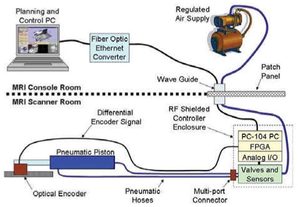
Diagram representing controller connection to a single representative actuator. All low-level control takes place inside of the scanner room; embedded computer and valves are in an enclosure placed in the scanner room at the foot of the bed and robot actuators and position sensors are inside of the scanner bore. The controller communicates with high-level planning software through a fiber optic connection.
Fig. 7.
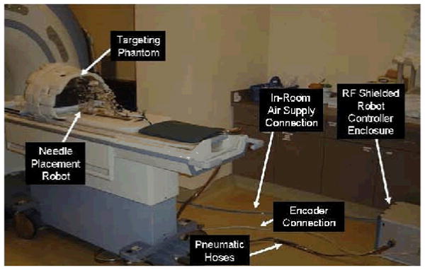
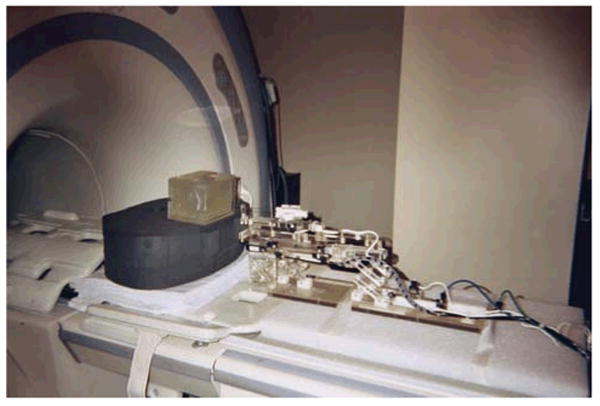
Configuration of robot for system evaluation trials. The robot resides on the table at a realistic relative position to the phantom. The controller operates in the room at a distance of only 2.5m from the 3T MRI scanner without functional difficulties or significant image quality degradation.
Pneumatic connections from the robot interface to the manipulator that is sitting on the bed in the scanner bore are simplified with a multi-port pneumatic connector and bundled air tubing that can accommodate up to 10 connections in a single plug. Encoder connections are made using a single standard 68 conductor twisted pair shielded cable that mates to the robot axes through a custom circuit board on the robot with individual connectors per axis as in Fig. 7. Communication with the planning and control workstation sitting in the MR console room is through a fiber optic ethernet connection. No electrical connections pass out of the scanner room limiting, thus significantly limiting the MR imaging interference.
F. Interface Software
Interface with the robot is via 3D Slicer-based5 software GUI running on the planning laptop PC in the scanner's console room and is described in detail in [21]. A DICOM server running on the planning workstation retrieves images from the scanner console. Both preoperative and intra-operative images can be loaded into the application for procedure planning and for intra-operative guidance. The Slicer workstation calculates the location of the robot with respect to the patient coordinate system based upon images of the tracking fiducial described in Section III-D. A target and entry point are chosen on the planning PC, and the robot is sent the coordinates and aligns the needle guide appropriately. In the current system, the needle is inserted manually while the needle position is monitored by an encoded slider and displayed in real-time on the display. Real-time MR images (0.5Hz) will be used during the insertion phase to ensure the target is reached. The reason for a keeping a human in the loop is to increase the safety of the needle insertion, and to allow for the live MRI images to help monitor progress. Fig. 8 shows the planning software with an MR image of the phantom loaded and the real-time feedback of the robot is used to generate the needle axis superimposed on the MR image.
Fig.8.
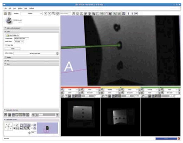
3D Slicer planning workstation showing a selected target and the real-time readout of the robot's needle position. The line represents a projection along the needle axis and the sphere represents the location of the needle tip.
IV. Results
The first iteration of the needle placement robot has been constructed and is operational; all mechanical, electrical, communications, and software issues have been resolved. The current state of the manipulator is two actuated DOF (vertical and horizontal) with an encoded passive needle insertion stage as shown in Fig. 5. Evaluation of the robot is in three distinct phase: 1) evaluation of the MR compatibility of the robot, 2) evaluation of the workspace and workflow, and 3) evaluation of the localization and placement accuracy.
The MR compatibility of the system is thoroughly evaluated in [17]. Using standard prostate imaging sequences (T1, T2 and TSE) the maximum loss in average signal to noise ration (SNR) was shown to be 5%. Qualitatively, prostate images were captured while the robot was operational is there is no readily identifiable loss of image quality when the robot is present.
The required workspace was evaluated prior to construction and has been confirmed by imaging patients in the appropriate position on the leg rest and verifying that all extents of the prostate are reachable. Further studies of this are underway where volunteers are imaged on the leg rest in the appropriate semi-lithotomy position and the prostate and anatomical constraints are analyzed. Accuracy assessment is broken into two parts: localization and placement. These two must be distinguished, especially in many medical applications. In prostate biopsy, it is essential to know exactly where a biopsy comes from in order to be able to forma treatment plan if cancer is located. In brachytherapy treatment, radioactive seed placement plans must be made to avoid cold spots where irradiation is insufficient; by knowing where seeds are placed, the treatment plan can be updated in real-time. Based on encoder resolution, localization accuracy of the robot is better than 0.1mm in all directions. Positioning accuracy is dependent on the servo pneumatic control system. With the controller hardware complete and a preliminary controller based upon standard PID techniques in place, the robot can be positioned within about 5mm; this represents the approximate targeting resolution in traditional ultrasound-guided transperineal prostate interventions. This accuracy is expected to be improved significantly as we refine the controller design. Development of novel pneumatic control architecture is underway, and the goal is for the target positioning accuracy to approach the resolution of the encoders. Experiments with sliding mode control algorithms that are more robust to the high friction of the mechanism show great promise, and we intend to achieve 0.1mm positioning accuracy per axis.
V. Conclusions and future works
We have developed an MRI-compatible manipulator and the support system architecture that can be used for needle placement in the prostate for biopsy and brachytherapy procedures. The robot has been designed such that it will operate in the confined space between the patient's legs inside a leg rest/tunnel in a high-field, closed bore MRI scanners. The configuration allows the use of diagnostic MRI scanners in interventional procedures; there is no need for open or large bore scanners that often are difficult to come by and sacrifice image quality. Evaluation of the system's workspace, MR-compatibility, workflow, and user interface has been very positive. All of the primary elements of the system are now in place; further refinement of the control system and interface software are in progress.
The next phase of this work focusses on generating clinical-grade system and preparing for Phase-1 clinical trials. The initial application will be prostate biopsy, followed later by brachytherapy seed placement. The design of the manipulator allows for treatment of patients that may have otherwise been denied such treatment because of contraindications such as significant pubic arch interference. The robot, controller and/or system architecture are generally applicable to other MR robotic applications. We intend to deploy a platform not only for prostate biopsy and brachytherapy, but also for injections, thermal ablation, and optical sensing modalities under MR image guidance.
Fig. 9.
Robotic system performing a needle insertion into a phantom in preliminary workflow evaluation experiments. Five out of five 1cm targets were successfully targeted.
Acknowledgments
This work was supported by NSF EEC-97-31478, NIH BRP RO1-CA111288-01, NIH/NIBIB R01-EB00296301, NIH U41-RR019703, and CDMRP PCRP Fellowship W81XWH-07-1-0171.
Footnotes
Airpel E9 Anti-stiction Air Cylinder -http://www.airpel.com
Hoerbiger-Origa PRE-U piezo valve-http://www.hoerbigeroriga.com
EM1-500 linear and E5D-1250 rotary encoder modules with PC5 differential line driver -US Digital, Vancouver, Washington
RTAI -http://www.rtai.org
3D Slicer -http://www.slicer.org
References
- 1.Jemal A, Siegel R, Ward E, Murray T, Xu J, Thun M. Cancer statistics, 2007. CA Cancer J Clin. 2007;57(1):43–66. doi: 10.3322/canjclin.57.1.43. [DOI] [PubMed] [Google Scholar]
- 2.Blasko JC, Mate T, Sylvester J, Grimm P, Cavanagh W. Brachytherapy for carcinoma of the prostate. Semin Radiat Oncol. 2002;12(1):81–94. doi: 10.1053/srao.2002.28667. [DOI] [PubMed] [Google Scholar]
- 3.Terris MK, Wallen EM, Stamey TA. Comparison of mid-lobe versus lateral systematic sextant biopsies in detection of prostate cancer. Urol Int. 1997;59:239–242. doi: 10.1159/000283071. [DOI] [PubMed] [Google Scholar]
- 4.D'Amico AV, Tempany CM, Cormack R, Hata N, Jinzaki M, Tuncali K, Weinstein M, Richie J. Transperineal magnetic resonance image guided prostate biopsy. JUrol. 2000;164(2):385–7. [PubMed] [Google Scholar]
- 5.Zangos S, Eichler K, Engelmann K, Ahmed M, Dettmer S, Herzog C, Pegios W, Wetter A, Lehnert T, Mack MG, Vogl TJ. MR-guided transgluteal biopsies with an open low-field system in patients with clinically suspected prostate cancer: technique and preliminary results. Eur Radiol. 2005;15(1):174–82. doi: 10.1007/s00330-004-2458-2. [DOI] [PubMed] [Google Scholar]
- 6.Susil RC, Camphausen K, Choyke P, McVeigh ER, Gustafson GS, Ning H, Miller RW, Atalar E, Coleman CN, Ménard C. System for prostate brachytherapy and biopsy in a standard 1.5 T MRI scanner. Magnetic Resonance in Medicine. 2004;52:683–6873. doi: 10.1002/mrm.20138. [DOI] [PMC free article] [PubMed] [Google Scholar]
- 7.Beyersdorff D, Winkel A, Hamm B, Lenk S, Loening SA, Taupitz M. MR imaging-guided prostate biopsy with a closed MR unit at 1.5 T. Radiology. 2005;234:576–581. doi: 10.1148/radiol.2342031887. [DOI] [PubMed] [Google Scholar]
- 8.Masamune K, Kobayashi E, Masutani Y, Suzuki M, Dohi T, Iseki H, Takakura K. Development of an MRI-compatible needle insertion manipulator for stereotactic neurosurgery. J Image Guid Surg. 1995;1(4):242–8. doi: 10.1002/(SICI)1522-712X(1995)1:4<242::AID-IGS7>3.0.CO;2-A. [DOI] [PubMed] [Google Scholar]
- 9.Felden A, Vagner J, Hinz A, Fischer H, Pfleiderer SO, Reichenbach JR, Kaiser WA. ROBITOM-robot for biopsy and therapy of the mamma. Biomed Tech (Berl) 2002;47:2–5. doi: 10.1515/bmte.2002.47.s1a.2. [DOI] [PubMed] [Google Scholar]
- 10.Hempel E, Fischer H, Gumb L, Hhn T, Krause H, Voges U, Breitwieser H, Gutmann B, Durke J, Bock M, Melzer A. An MRI-compatible surgical robot for precise radiological interventions. CAS. 2003 Apr;:180–191. doi: 10.3109/10929080309146052. [DOI] [PubMed] [Google Scholar]
- 11.Chinzei K, Hata N, Jolesz FA, Kikinis R. MR compatible surgical assist robot: system integration and preliminary feasibility study. MICCAI. 2000 Oct;1935:921–933. [Google Scholar]
- 12.DiMaio SP, Pieper S, Chinzei K, Fichtinger G, Tempany C, Kikinis R. Robot assisted percutaneous intervention in open-MRI. MRI Symp. 2004:155. [Google Scholar]
- 13.Krieger A, Susil RC, Menard C, Coleman JA, Fichtinger G, Atalar E, Whitcomb LL. Design of a novel MRI compatible manipulator for image guided prostate interventions. IEEE TBME. 2005 Feb;52:306–313. doi: 10.1109/TBME.2004.840497. [DOI] [PMC free article] [PubMed] [Google Scholar]
- 14.Muntener M, Patriciu A, Petrisor D, Mazilu D, Bagga H, Kavoussi L, Cleary K, Stoianovici D. MRI compatible robotic system for fully automated brachytherapy seed placement. J Urology. 2006;68:1313–7. doi: 10.1016/j.urology.2006.08.1089. [DOI] [PMC free article] [PubMed] [Google Scholar]
- 15.Taillant E, Avila-Vilchis J, Allegrini C, Bricault I, Cinquin P. CT and MR Compatible Light Puncture Robot: Architectural Design and First Experiments. MICCAI. 2004;3217:145–152. [Google Scholar]
- 16.Gassert R, Moser R, Burdet E, Bleuler H. MRI/fMRI-Compatible Robotic System With Force Feedback for Interaction With Human Motion. T Mech. 2006 Apr;11(2):216–24. [Google Scholar]
- 17.Fischer GS, DiMaio SP, Iordachita I, Fichtinger G. Development of a Robotic Assistant for Needle-Based Transperineal Prostate Interventions in MRI. MICCAI. 2007 Nov;:425–433. doi: 10.1007/978-3-540-75757-3_52. [DOI] [PubMed] [Google Scholar]
- 18.Wallner K, Blasko J, Dattoli M. Prostate Brachytherapy Made Complicated. 2nd. SmartMedicine Press; 2001. [Google Scholar]
- 19.Elhawary H, Zivanovic A, Rea M, Davies B, Besant C, McRobbie D, de Souza N, Young I, Lamprth M. The Feasibility of MR-Image Guided Prostate Biopsy Using Piezoceramic Motors Inside or Near to the Magnet Isocentre. MICCAI. 2006 Nov;:519–526. doi: 10.1007/11866565_64. [DOI] [PubMed] [Google Scholar]
- 20.DiMaio SP, Samset E, Fischer GS, Iordachita I, Fichtinger G, Jolesz F, Tempany C. Dynamic MRI Scan Plane Control for Passive Tracking of Instruments and Devices. MICCAI. 2007 Nov;:50–58. doi: 10.1007/978-3-540-75759-7_7. [DOI] [PubMed] [Google Scholar]
- 21.Mewes PW, Tokuda J, DiMaio SP, Fischer GS, Csoma C, Gobbi DG, Tempany CM, Fichtinger G, Hata N. An Integrated MRI and Robot Control Software System for an MRI-compatible Robot in Prostate Intervention. IEEE ICRA. 2008 Apr; [Google Scholar]


