Abstract
Comprehensive microscopy of distal esophagus could greatly improve the screening and surveillance of esophageal diseases such as Barrett’s esophagus by providing histomorphologic information over the entire region at risk. Spectrally encoded confocal microscopy (SECM) is a high-speed reflectance confocal microscopy technology that can be configured to image the entire distal esophagus by helically scanning the beam using optics within a balloon-centering probe. It is challenging to image the human esophagus in vivo with balloon-based SECM, however, because patient motion and anatomic tissue surface irregularities decenter the optics, making it difficult to keep the focus at a predetermined location within the tissue as the beam is scanned. In this paper, we present a SECM probe equipped with an adaptive focusing mechanism that can compensate for tissue surface irregularity and dynamic focal variation. A tilted arrangement of the objective lens is employed in the SECM probe to provide feedback signals to an adaptive focusing mechanism. The tilted configuration also allows the probe to obtain reflectance confocal data from multiple depth levels, enabling the acquisition of three-dimensional volumetric data during a single scan of the probe. A tissue phantom with a surface area of 12.6 cm2 was imaged using the new SECM probe, and 8 large-area reflectance confocal microscopy images were acquired over the depth range of 56 μm in 20 minutes. Large-area SECM images of excised swine small intestine tissue were also acquired, enabling the visualization of villous architecture, epithelium, and lamina propria. The adaptive focusing mechanism was demonstrated to enable acquisition of in-focus images even when the probe was not centered and the tissue surface was irregular.
OCIS codes: (170.1790) Confocal microscopy, (170.2150) Endoscopic imaging, (170.2680) Gastrointestinal
1. Introduction
The diagnosis of Barrett’s esophagus (BE), dysplasia, and intramucosal carcinoma remains an important clinical problem. Video endoscopy, the first-line imaging method used for examination of the esophagus, does not have the contrast or microscopic resolution required to reliably detect the morphologic changes associated with BE progression. As a result, the diagnosis of BE progression currently relies on histopathologic examination of tissues obtained from random endoscopic biopsy. However, this method only allows a very small fraction of the region at risk to be examined and often fails to represent the overall disease status [1].
Comprehensive microscopy of the entire distal esophagus offers the potential to provide a more accurate accounting of disease status. Previously, optical frequency domain imaging (OFDI) has been demonstrated to be capable of imaging the entire distal esophagus in vivo through a balloon-centering catheter [2,3]. The diagnostic information provided by OFDI can be further used to guide the endoscopic biopsy, which may reduce sampling errors and can enhance diagnostic accuracy [4]. While OFDI can clearly visualize architectural morphology, cellular features that may be required for the most accurate diagnosis are not well appreciated by OFDI because of its resolution, which is on the order of 10-20 µm.
Confocal laser endomicroscopy (CLE) can visualize cellular and sub-cellular morphology of internal organ tissues in vivo [5–14]. Previous studies have shown that CLE can differentiate intestinal metaplasia from normal esophageal tissues [6,15,16], and neoplastic changes from intestinal metaplasia [6,15–17]. However, the field size of CLE is typically limited to ~500 µm × 500 µm. As a result, only small fractions of the surface area at risk can be examined during an endoscopy session, and therefore CLE is likely subject to sampling errors that are similar to those found with endoscopic biopsy [1]. Mosaicing CLE images together has been demonstrated to generate larger confocal images [18,19]. Even with mosaicing, the frame rate of CLE and the requirement of near contact imaging prohibit interrogation of the entire distal esophagus in realistic procedure times, however.
Spectrally encoded confocal microscopy (SECM) is a confocal microscopy technology that is capable of obtaining images at a rate that is 10 to 100 times faster than that of conventional confocal microscopy systems [20]. With SECM, a diffraction grating and an objective lens at the distal tip of an optical fiber are used to illuminate different spatial locations on the specimen with distinct spectral bands. Reflected light from the specimen is transferred back through the grating-objective pair and the fiber to the system console. Within the SECM system, one line of the confocal microscopy image is rapidly acquired by measuring the spectral content of the remitted light using a high-speed spectrometer (broadband input) or a high-bandwidth photodetector (wavelength swept source input). The other dimension of the image is obtained while scanning the grating-objective pair perpendicularly to the spectrally encoded line. In a clinical study of imaging esophageal biopsy samples, SECM has been demonstrated to visualize architectural and cellular features similar to those used for histologic diagnosis [21]. In an earlier work, the feasibility of imaging large luminal organs was demonstrated [22] using a bench top setup designed to simulate SECM imaging through a balloon-centering probe. In this paper, the spectrally encoded line was helically scanned across static cylindrical specimens with similar dimensions to the human distal esophagus. This device captured large-area confocal images at a fixed focal distance and needed to conduct multiple helical scans at different focal locations to acquire volumetric data [22].
One key challenge for conducting comprehensive esophageal imaging in vivo with SECM is that the focal plane of the objective lens must be consistently kept at a designated imaging depth within the tissue. Because the numerical aperture (NA) is large in SECM (~0.5), the confocal parameter or depth of focus is small, making the device very sensitive to variations in the distance between the probe and the tissue. Maintaining a constant focal distance is therefore quite difficult in the presence of tissue surface irregularity and motion encountered when imaging living patients. In this paper, we present a SECM probe equipped with an adaptive focusing mechanism that senses the tissue surface and automatically adjusts the focal location of the objective lens while the probe scans the tissue. We demonstrate the capability of the focusing mechanism to compensate for the tissue surface irregularity and the motion artifacts that are similar to those present when imaging in vivo. Additionally, we show that the new probe design enables the acquisition of optically-sectioned images at multiple imaging depth levels during a single helical scan of the probe, a capability that greatly simplifies the imaging procedure and provides three-dimensional confocal microscopy information.
2. Methods
2.1. SECM probe
Figure 1 shows a schematic diagram of the bench top SECM probe. A supercontinum laser (SC400-2, Fianium, UK; spectral density = 1 mW/nm) was used as a light source. A portion of the spectrum of the source with the bandwidth of 30 nm centered at 877 nm was used for SECM imaging. The light from the source was coupled into a 50/50 fiber-optic beam splitter and one output port of the beam splitter was coupled into the probe through a single-mode fiber. Light from the fiber was collimated by a lens (f = 20 mm) and dispersed by a transmission holographic grating (1700 lines/mm) into 343 resolvable points. The dispersed light was focused onto a specimen by an objective lens (aspheric singlet lens; f = 4.5 mm; effective NA = 0.53) through a transparent plastic tube (diameter = 20 mm; thickness = 50 µm). The plastic tube was designed to simulate a centering balloon, similar to that used for the comprehensive OFDI imaging of the distal esophagus [3]. The objective lens was scanned along the axial (depth) dimension by a focusing mechanism, comprising a miniature linear guide and a piezo-electric transducer (PZT) actuator (TULA35, Piezoelectric Technology, South Korea; maximum speed = 27 mm/sec; maximum motion range = 10.6 mm) [23]. The probe was scanned helically by a motor and a translation stage to obtain large-area images of the cylindrical specimen, which was affixed on the outer surface of the plastic tube. The optical power on the specimen was measured to be 6.0 mW. The SECM probe (inset of Fig. 1) was built with the dimensions of 10 mm (W) × 39 mm (L) × 13 mm (H).
Fig. 1.
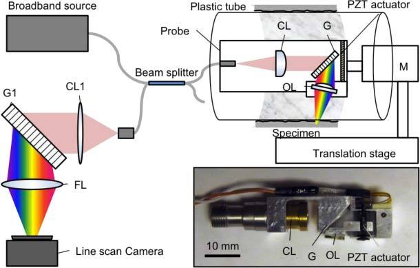
Schematic and photo (inset) of SECM probe. CL – collimation lens; G – Grating; PZT – piezo-electric transducer; OL – Objective lens; M – motor; FL – focusing lens.
The reflected light was coupled back into the beam splitter and directed to a spectrometer composed of a collimation lens (f = 44 mm), a grating (1800 lines/mm), a focusing lens (f = 200 mm) and a line scan camera (Spl2k-140k, Basler, Germany; pixel size = 10 μm; 2048 pixels). The resolution of the spectrometer was 0.04 nm.
2.2. Adaptive focusing
In order to generate feedback signal for the adaptive focusing mechanism, a special optical configuration was employed in the SECM probe. As shown in Fig. 2A , the objective lens of the probe was tilted with respect to the tissue surface, making the SECM focal line also tilted relative to the tissue surface. The tilt angle of the objective lens was set to be 5.7°, providing a good compromise between the range of depths over which SECM data could be acquired and optical performance.
Fig. 2.
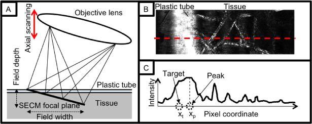
Feedback signal generation method: A. schematic diagram of spectrally encoded illumination on tissue; B. Exemplary image of SECM; and C. Intensity profile along the dotted line in (B).
Since the SECM focal line extended over a range of depths, the location of the tissue surface with respect to the SECM focal locations was obtainable by analyzing SECM images. In Fig. 2B, a representative SECM image shows both the plastic tube and the tissue. The intensity profile (Fig. 2C) along the dotted line in Fig. 2B demonstrates that the tissue surface exhibits high intensity due to the large refractive index gradient between the plastic tube and the tissue. Therefore depth information of the tissue surface relative to the SECM focal plane was obtained by calculating the peak coordinate of the high-intensity region.
The feedback control signal S was then determined by the following equation:
| (1) |
where KP was the gain constant, and xp and xt were the coordinates of the peak and target positions, respectively. The objective lens was translated along the depth dimension to minimize the difference between the tissue surface coordinate xp and the target coordinate xt, which subsequently moved the SECM focal plane to a designated target depth below the tissue surface. The feedback signal S was converted to TTL pulses that drove the PZT actuator: the absolute value determined the number of TTL pulses (frequency = 90 kHz), and the sign the duty cycle (0.23 and 0.77 for positive and negative values of S, respectively). During the helical scanning of the SECM probe, line images were acquired at a rate of 25 kHz, and one out of every 200 line images was used for calculating the control signal, resulting in the control signal update rate of 125 Hz.
2.3. Volumetric imaging
Utilizing the tilted objective lens configuration where multiple depth levels were simultaneously interrogated in a SECM image, the SECM probe inherently acquired three-dimensional volumetric data during a single helical scan. However, the parameters for the scanning of the probe needed to be carefully selected to ensure seamless sampling of the tissue at each depth level. The number of distinct depth levels that can be effectively obtained in a single SECM image, N, was calculated by dividing the field depth by the axial resolution. The longitudinal scan step size was then determined by dividing the field width by N, resulting in N images of the tissue sampled at different depths, continuously during a helical scan of the probe (Fig. 3 ).
Fig. 3.
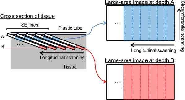
Method of reconfiguring a SECM image data set into multiple large-area confocal images at different depth levels. SE lines – spectrally encoded lines.
Once the image acquisition was complete, the volumetric data was reconfigured to generate large-area en face confocal images at the different depth levels. First, each image strip obtained from a single circumferential scan of the SECM probe was divided into N segments. Image segments from the same depth level were then stitched together to generate a large-area confocal image at each depth level (Fig. 3).
3. Results
The transverse resolution of the adaptive ranging SECM probe was measured by imaging a USAF resolution target (Fig. 4 ). The smallest line/space pattern with the bar width of 2.2 µm was clearly resolved. The FWHM of the line-spread function (LSF) ranged from 1.25 ± 0.13 μm to 1.45 ± 0.33 μm, from the center to the edges of the field of view (FOV), respectively. The field width was measured to be 400 μm by imaging a 100-lines/mm grating. Along the axial dimension, the field depth was measured to be 56 μm, and the resolution was 4.4 μm and 10 μm at the center and the edges of the FOV, respectively.
Fig. 4.
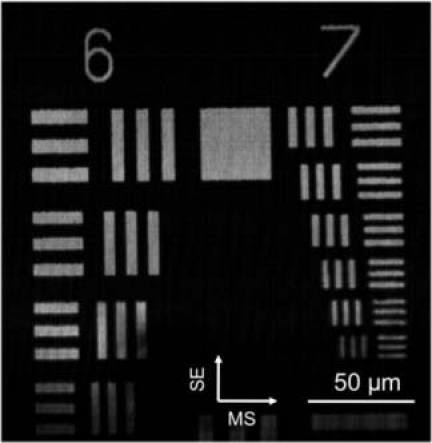
Image of USAF 1951 resolution target. SE – spectrally encoded axis; MS – motor scanning axis.
The performance of the adaptive focusing mechanism was evaluated by tracking a mirror moving in a sinusoidal motion. The adaptive focusing mechanism was able to follow the sinusoidal motion of the mirror with a displacement amplitude of 250 μm and a frequency of 1 Hz. The motion range of the focusing mechanism was 3 mm, limited mainly by the optics layout.
Figure 5 shows SECM image data for a complete pullback image of a 2.0-cm-long tissue phantom without adaptive focusing (Figs. 5A, B) and with adaptive focusing on (Figs. 5C, D). The tissue phantom consisted of lens paper affixed to the outer surface of the plastic tube. The probe was scanned using a rotation rate of 20 rpm, and a total of 400 circumferential scans were acquired in 20 minutes. Since the field width was 400 μm, the longitudinal step size of 50 μm provided en face confocal images at 8 different depth levels spaced by 7 μm. Images shown in Fig. 5 are en face confocal images obtained from the fourth depth level from the top. At low magnification (Figs. 5A, C), the macroscopic structure of the paper, including folds and voids, is visible. When regions of this data set are shown at higher magnifications, individual fibers and fiber microstructure can be clearly resolved (Figs. 5B, D and Fig. 5D, inset). When the adaptive focusing mechanism was utilized (Figs. 5C, D), the entire data set remained in focus, even when the probe was not centered and the tissue surface was irregular. In contrast, when the focusing mechanism was off, only small portions of the tissue phantom were in focus and visible (Figs. 5A, B). A stack of en face confocal images acquired at 8 different depth levels is shown in Fig. 6 . Morphologic changes in the images are clearly observed at the different depth levels (note the circled region), validating the optical sectioning capability of the SECM probe.
Fig. 5.
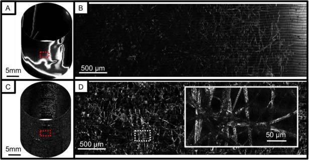
Images of a lens paper phantom: A. cylindrical presentation of image obtained without adaptive focusing; B. magnified view of (A); C. cylindrical presentation of image obtained with adaptive focusing; and D. magnified view of (C).
Fig. 6.
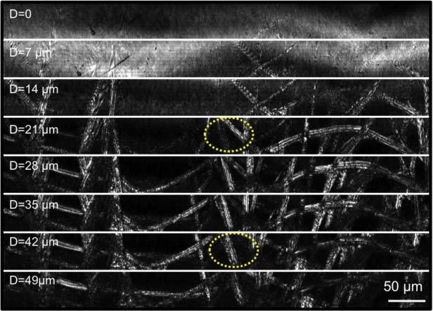
Images of a lens paper phantom obtained at different imaging depth levels.
In order to test the imaging capability of this probe in biological tissues, a portion of an excised swine small intestine was imaged with the SECM probe. The swine tissue was treated with 5% acetic acid to enhance the image contrast and placed on the top half surface of the plastic tube. The probe was rotated at a speed of 10 rpm. The image acquisition time for a total of 200 circumferential scans over a 1.0-cm-long and 3.1-cm-wide tissue area was 10 minutes. Due to the low level of the detected intensity, the exposure time of the line scan camera was increased, resulting in the effective line rate of 5 kHz. Optically-sectioned SECM images obtained from the fourth depth level from the top are shown in Fig. 7 . The SECM image obtained without adaptive focusing (Fig. 7A) shows strong reflection from the plastic tube on the left (arrow), and it is impossible to visualize any morphologic features of the tissue over most of the imaged region. In contrast, the SECM image obtained with adaptive focusing on (Fig. 7B) shows gross architecture of the tissue over most of the imaged area. There are however regions where the tissue morphology was not visualized (dotted arrow in Fig. 7B), accounting for approximately 2% of the entire imaged area. Optically-sectioned images obtained from multiple depth levels (Fig. 8A ) allow clear visualization of the characteristic villous architecture of the swine small intestinal tissue and the tissue morphology changes at different depth levels. A magnified view (Fig. 8B) of the boxed region in Fig. 8A demonstrates both epithelium (E) and lamina propria (LP).
Fig. 7.
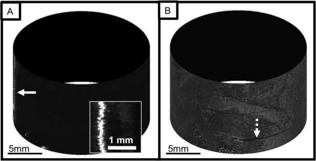
Images of a swine small intestine tissue: A. cylindrical presentation of image obtained without adaptive focusing and magnified view (inset); and B. cylindrical presentation of image obtained with adaptive focusing.
Fig. 8.
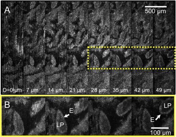
Images of a swine small intestine tissue: A. SECM images obtained from different depth levels; and B. magnified view of the dotted box in (A). LP – lamina propria; E – epithelium.
4. Discussions
In this paper, we have demonstrated a SECM probe that comprehensively images luminal specimens while adaptively adjusting the focus so that it always resides within the tissue. The images of a tissue phantom and an excised swine tissue demonstrated the effectiveness of the adaptive focusing mechanism and the feasibility of acquiring three-dimensional volumetric images using a single helical scan of the probe. Several technical challenges need to be addressed before the SECM probe is applicable for human imaging in vivo, however.
The image acquisition speed in this study, 25-kHz line rate, was slower than the maximum speed of the line scan camera in the spectrometer, 70 kHz, mainly due to the method used for generating the feedback control signal. The control signal was created within the image acquisition software coded in the LabVIEW platform (National Instruments, Austin, TX), and the computational burden of generating the control signal in this programming environment limited the image acquisition speed. Developing more efficient code would allow the image acquisition to fully utilize the maximum speed of the line scan camera. The image acquisition speed can be also increased by separating the feedback control signal generation from the image acquisition software. A simple optoelectronic apparatus comprising a grating, a position-sensitive detector (PSD; i.e. quadrant photodetector), and an electric control circuit could be used to analyze a portion of the spectrum of the returning light from the SECM probe and generate a control signal independently of the image acquisition software.
The imaging speed needed to be further reduced when imaging biological tissues due to the low level of detected intensity. The light throughput of the SECM probe was only 2%, partly caused by the use of off-the-shelf optical components that were not optimized for the wavelengths of light used in our setup. We can improve the light throughput by customizing the optical components, and can utilize a supercontinuum source with a 3 times higher spectral density (SC450-6, Fianium, UK) than the present source, resulting in an order-of-magnitude improved sensitivity, thereby allowing the line scan camera to operate at its maximum speed.
The adaptive focusing mechanism was demonstrated to provide in-focus images over most of the imaged areas (Figs. 5C and 7B). However, due to the slow update rate of the control signal, there were regions where the adaptive focusing did not track the tissue surface reliably (dotted arrow in Fig. 7B). In our experiment, the control signal was updated discretely at a rate of 125 Hz; rapid changes of the focal distance during this 8-msec interval caused the tissue surface to be outside of the focus of the SECM probe. More frequent updates of the control signal will enable improved continuous tracking of the tissue surface and provide in-focus images over even larger areas. Higher control signal throughput can be achieved by developing more efficient code and/or employing an independent apparatus of generating the control signal as mentioned previously.
Increasing the control signal update rate will also enhance the dynamic performance of the adaptive focusing. The current adaptive focusing mechanism can track up to a 1-Hz dynamic focal deviation with a displacement amplitude of 250 µm. Based on previous experience in esophageal imaging of living animals and human patients with a balloon-centering catheter [2,3], a focal deviation of ±250 µm at the rate of 2 Hz is anticipated in human esophageal imaging. With the improvement on the update rate described in the previous paragraph, we anticipate that the adaptive focusing mechanism will be able to reliably track the dynamic focal deviations encountered when imaging human patients.
We used a PZT-driven linear actuator for adaptive focusing in this paper due to its small size, large travel range and fast moving speed. Several other variable focusing methods have been previously studied for endoscopic microscopy applications, including moving the distal tip of the fiber pneumatically and mechanically [24] and using a pressure-controlled variable focus liquid lens [25]. However these methods need significant modifications to transfer the force or the pressure rapidly from the proximal end to a rotating SECM probe. MEMS deformable mirrors have been used to change the imaging depth of optical coherence tomography (OCT) [26] and are expected to provide a focusing range as large as 1mm for an objective lens with NA of 0.4 [27]. Electrically-tunable varifocal liquid lenses [28] and voice-coil motors [29] have been used to conduct auto-focusing in cell-phone cameras. In future probe development, we will investigate these electrically-driven variable focusing mechanisms and will select a method that meets the requirements of SECM imaging and that can be integrated within a rotating imaging probe.
While the SECM images of a resolution target and a tissue phantom demonstrated that the SECM probe has good transverse resolution, cellular features were not clearly visualized in the swine tissue images. The off-the-shelf aspheric singlet that was used as the objective lens was designed for use in air, which increased the specular reflection from the tissue surface and caused spherical aberration when imaging below the tissue surface. In the future, we will fabricate a custom objective lens that allows for water immersion and will fill the centering balloon with the immersion medium, decreasing the specular reflection and the spherical aberration and subsequently enabling high-resolution imaging of sub-surface regions of the tissue. Speckle noise presented in the SECM images also made it hard to appreciate cellular features. The speckle noise will be reduced utilizing a single-mode illumination and multi-mode detection method though a double-clad fiber [30,31]. Although the rotational scan of the probe provided good spatial registration between circumferential scans and generated large-area images without noticeable stitching artifacts (Figs. 5, 7 and 8), there were locations where non-uniformity of the motor rotation speed made it difficult to mosaic circumferential scans together with microscopic precision. The rotational non-uniformity was primarily caused by the low torque capacity of the motor. We will utilize a motor and a driveshaft with a higher torque capacity to provide more uniform rotation of the probe. A rotary encoder can be integrated into the probe to measure the actual rotation speed, which can be used to correct the image distortions generated by residual rotational non-uniformity.
The spectral bandwidth of 30 nm was dispersed over 1024 pixels of the line scan camera, resulting in an effective coherence length of 11 mm. While interference fringes were not likely generated from the probe optics due to the anti-reflection coating of each component, relatively large distances between the components, and confocal gating, interference between back-reflections from the inner and outer surfaces of the plastic tube generated visible fringes (Fig. 5B). We expect that the water-immersion approach described above will significantly reduce the back-reflection from the tube’s inner surface and will subsequently decrease the visibility of the interference fringes. When imaging lens paper, fringe patterns were imposed on the SECM images obtained from superficial regions (D = 14 µm in Fig. 6), caused by the interference between reflections from the tube outer surface and the specimen. However, fringe patterns were not observed when imaging swine tissue because the constant contact between the plastic tube and the tissue reduced the back-reflection from the outer surface of the tube.
The sub-optimal performance of the aspheric objective lens also limited the field depth to 56 µm. In the next version of our SECM probe for human imaging, we will increase the field depth to 100 µm by designing a custom objective lens that has a larger diffraction-limited FOV for the spectral band of interest. Since most epithelial disorders manifest near the surface, an imaging depth range of 100 µm is expected to provide sufficient histomorphologic information to render accurate diagnosis.
The next step in our research will be to construct a clinically-viable SECM probe that can be used in human patients. The technology development will be focused on addressing the challenges discussed above and reducing the probe size further. We anticipate that the next-generation clinical SECM probe will acquire volumetric confocal images of the entire distal esophagus with a volume of 39 cm2 (surface area) × 100 µm (ranging depth) in less than 10 minutes. Following the image acquisition, the comprehensive volumetric data will be analyzed to locate regions with high probabilities of harboring severe dysplasia or early cancer. The SECM probe can then be repositioned to the identified high-risk regions, and high-power laser light will be delivered through the SECM probe to generate laser-burn marks around the regions [4]. The marks will be visible under video endoscopy, and clinicians will be able to take biopsies from the high-risk regions rather than random locations, which will increase the likelihood that patients will receive a much more accurate diagnosis than the current standard of care.
Acknowledgments
This research was sponsored by National Institute of Health/National Cancer Institute (Grants R21CA122161 and R21 CA141884). Priyanka Jillella is currently with the University of Arizona.
References and links
- 1.Falk G. W., Rice T. W., Goldblum J. R., Richter J. E., “Jumbo biopsy forceps protocol still misses unsuspected cancer in Barrett’s esophagus with high-grade dysplasia,” Gastrointest. Endosc. 49(2), 170–176 (1999). 10.1016/S0016-5107(99)70482-7 [DOI] [PubMed] [Google Scholar]
- 2.Vakoc B. J., Shishko M., Yun S. H., Oh W.-Y., Suter M. J., Desjardins A. E., Evans J. A., Nishioka N. S., Tearney G. J., Bouma B. E., “Comprehensive esophageal microscopy by using optical frequency-domain imaging (with video),” Gastrointest. Endosc. 65(6), 898–905 (2007). 10.1016/j.gie.2006.08.009 [DOI] [PMC free article] [PubMed] [Google Scholar]
- 3.Suter M. J., Vakoc B. J., Yachimski P. S., Shishkov M., Lauwers G. Y., Mino-Kenudson M., Bouma B. E., Nishioka N. S., Tearney G. J., “Comprehensive microscopy of the esophagus in human patients with optical frequency domain imaging,” Gastrointest. Endosc. 68(4), 745–753 (2008). 10.1016/j.gie.2008.05.014 [DOI] [PMC free article] [PubMed] [Google Scholar]
- 4.Suter M. J., Jillella P. A., Vakoc B. J., Halpern E. F., Mino-Kenudson M., Lauwers G. Y., Bouma B. E., Nishioka N. S., Tearney G. J., “Image-guided biopsy in the esophagus through comprehensive optical frequency domain imaging and laser marking: a study in living swine,” Gastrointest. Endosc. 71(2), 346–353 (2010). 10.1016/j.gie.2009.07.007 [DOI] [PMC free article] [PubMed] [Google Scholar]
- 5.Kiesslich R., Burg J., Vieth M., Gnaendiger J., Enders M., Delaney P., Polglase A., McLaren W., Janell D., Thomas S., Nafe B., Galle P. R., Neurath M. F., “Confocal laser endoscopy for diagnosing intraepithelial neoplasias and colorectal cancer in vivo,” Gastroenterology 127(3), 706–713 (2004). 10.1053/j.gastro.2004.06.050 [DOI] [PubMed] [Google Scholar]
- 6.Kiesslich R., Gossner L., Goetz M., Dahlmann A., Vieth M., Stolte M., Hoffman A., Jung M., Nafe B., Galle P. R., Neurath M. F., “In vivo histology of Barrett’s esophagus and associated neoplasia by confocal laser endomicroscopy,” Clin. Gastroenterol. Hepatol. 4(8), 979–987 (2006). 10.1016/j.cgh.2006.05.010 [DOI] [PubMed] [Google Scholar]
- 7.Polglase A. L., McLaren W. J., Skinner S. A., Kiesslich R., Neurath M. F., Delaney P. M., “A fluorescence confocal endomicroscope for in vivo microscopy of the upper- and the lower-GI tract,” Gastrointest. Endosc. 62(5), 686–695 (2005). 10.1016/j.gie.2005.05.021 [DOI] [PubMed] [Google Scholar]
- 8.Kiesslich R., Goetz M., Burg J., Stolte M., Siegel E., Maeurer M. J., Thomas S., Strand D., Galle P. R., Neurath M. F., “Diagnosing Helicobacter pylori in vivo by confocal laser endoscopy,” Gastroenterology 128(7), 2119–2123 (2005). 10.1053/j.gastro.2004.12.035 [DOI] [PubMed] [Google Scholar]
- 9.Meining A., Phillip V., Gaa J., Prinz C., Schmid R. M., “Pancreaticoscopy with miniprobe-based confocal laser-scanning microscopy of an intraductal papillary mucinous neoplasm (with video),” Gastrointest. Endosc. 69(6), 1178–1180 (2009). 10.1016/j.gie.2008.06.013 [DOI] [PubMed] [Google Scholar]
- 10.Thiberville L., Moreno-Swirc S., Vercauteren T., Peltier E., Cavé C., Bourg Heckly G., “In vivo imaging of the bronchial wall microstructure using fibered confocal fluorescence microscopy,” Am. J. Respir. Crit. Care Med. 175(1), 22–31 (2006). 10.1164/rccm.200605-684OC [DOI] [PubMed] [Google Scholar]
- 11.Neumann H., Kiesslich R., Wallace M. B., Neurath M. F., “Confocal laser endomicroscopy: technical advances and clinical applications,” Gastroenterology 139(2), 388–392e2 (2010). 10.1053/j.gastro.2010.06.029 [DOI] [PubMed] [Google Scholar]
- 12.Shahid M. W., Wallace M. B., “Endoscopic imaging for the detection of esophageal dysplasia and carcinoma,” Gastrointest. Endosc. Clin. N. Am. 20(1), 11–24, v (2010). 10.1016/j.giec.2009.08.006 [DOI] [PubMed] [Google Scholar]
- 13.Wallace M. B., Kiesslich R., “Advances in endoscopic imaging of colorectal neoplasia,” Gastroenterology 138(6), 2140–2150 (2010). 10.1053/j.gastro.2009.12.067 [DOI] [PubMed] [Google Scholar]
- 14.Hoffman A., Goetz M., Vieth M., Galle P. R., Neurath M. F., Kiesslich R., “Confocal laser endomicroscopy: technical status and current indications,” Endoscopy 38(12), 1275–1283 (2006). 10.1055/s-2006-944813 [DOI] [PubMed] [Google Scholar]
- 15.Muldoon T. J., Anandasabapathy S., Maru D., Richards-Kortum R., “High-resolution imaging in Barrett’s esophagus: a novel, low-cost endoscopic microscope,” Gastrointest. Endosc. 68(4), 737–744 (2008). 10.1016/j.gie.2008.05.018 [DOI] [PMC free article] [PubMed] [Google Scholar]
- 16.Meining A., Saur D., Bajbouj M., Becker V., Peltier E., Höfler H., von Weyhern C. H., Schmid R. M., Prinz C., “In vivo histopathology for detection of gastrointestinal neoplasia with a portable, confocal miniprobe: an examiner blinded analysis,” Clin. Gastroenterol. Hepatol. 5(11), 1261–1267 (2007). 10.1016/j.cgh.2007.05.019 [DOI] [PubMed] [Google Scholar]
- 17.Pohl H., Rösch T., Vieth M., Koch M., Becker V., Anders M., Khalifa A. C., Meining A., “Miniprobe confocal laser microscopy for the detection of invisible neoplasia in patients with Barrett’s oesophagus,” Gut 57(12), 1648–1653 (2008). 10.1136/gut.2008.157461 [DOI] [PubMed] [Google Scholar]
- 18.Becker V., Vercauteren T., von Weyhern C. H., Prinz C., Schmid R. M., Meining A., “High-resolution miniprobe-based confocal microscopy in combination with video mosaicing (with video),” Gastrointest. Endosc. 66(5), 1001–1007 (2007). 10.1016/j.gie.2007.04.015 [DOI] [PubMed] [Google Scholar]
- 19.Loewke K., Camarillo D., Piyawattanametha W., Breeden D., Salisbury K., “Real-time image mosaicing with a hand-held dual-axes confocal microscope,” Proc. SPIE 6851, 68510F–, 68510F-9. (2008). 10.1117/12.764322 [DOI] [Google Scholar]
- 20.Tearney G. J., Webb R. H., Bouma B. E., “Spectrally encoded confocal microscopy,” Opt. Lett. 23(15), 1152–1154 (1998). 10.1364/OL.23.001152 [DOI] [PubMed] [Google Scholar]
- 21.Kang D., Suter M. J., Boudoux C., Yoo H., Yachimski P. S., Puricelli W. P., Nishioka N. S., Mino-Kenudson M., Lauwers G. Y., Bouma B. E., Tearney G. J., “Comprehensive imaging of gastroesophageal biopsy samples by spectrally encoded confocal microscopy,” Gastrointest. Endosc. 71(1), 35–43 (2010). 10.1016/j.gie.2009.08.026 [DOI] [PMC free article] [PubMed] [Google Scholar]
- 22.Yelin D., Boudoux C., Bouma B. E., Tearney G. J., “Large area confocal microscopy,” Opt. Lett. 32(9), 1102–1104 (2007). 10.1364/OL.32.001102 [DOI] [PubMed] [Google Scholar]
- 23.H. Park, B. Kim, J.-O. Park, and S.-J. Yoon, “A crawling based locomotive mechanism using a tiny ultrasonic linear actuator (TULA),” in 39th International Symposium on Robotics 2008 (International Federation of Robotics, Frankfort, Germany, 2008), pp. 85–90. [Google Scholar]
- 24.Rouse A. R., Kano A., Udovich J. A., Kroto S. M., Gmitro A. F., “Design and demonstration of a miniature catheter for a confocal microendoscope,” Appl. Opt. 43(31), 5763–5771 (2004). 10.1364/AO.43.005763 [DOI] [PubMed] [Google Scholar]
- 25.Aljasem K., Werber A., Seifert A., Zappe H., “Fiber optic tunable probe for endoscopic optical coherence tomography,” J. Opt. A, Pure Appl. Opt. 10(4), 044012 (2008). 10.1088/1464-4258/10/4/044012 [DOI] [Google Scholar]
- 26.Yang V. X. D., Mao Y., Standish B. A., Munce N. R., Chiu S., Burnes D., Wilson B. C., Vitkin I. A., Himmer P. A., Dickensheets D. L., “Doppler optical coherence tomography with a micro-electro-mechanical membrane mirror for high-speed dynamic focus tracking,” Opt. Lett. 31(9), 1262–1264 (2006). 10.1364/OL.31.001262 [DOI] [PubMed] [Google Scholar]
- 27.Dickensheets D. L., “Requirements of MEMS membrane mirrors for focus adjustment and aberration correction in endoscopic confocal and optical coherence tomography imaging instruments,” J. Micro/Nanolithogr. MEMS MOEMS 7(2), 021008–021009 (2008). 10.1117/1.2911024 [DOI] [Google Scholar]
- 28.Kuiper S., Hendriks B. H. W., “Variable-focus liquid lens for miniature cameras,” Appl. Phys. Lett. 85(7), 1128–1130 (2004). 10.1063/1.1779954 [DOI] [Google Scholar]
- 29.Liu C.-S., Lin P. D., “A miniaturized low-power VCM actuator for auto-focusing applications,” Opt. Express 16(4), 2533–2540 (2008). 10.1364/OE.16.002533 [DOI] [PubMed] [Google Scholar]
- 30.Yelin D., Bouma B. E., Yun S. H., Tearney G. J., “Double-clad fiber for endoscopy,” Opt. Lett. 29(20), 2408–2410 (2004). 10.1364/OL.29.002408 [DOI] [PubMed] [Google Scholar]
- 31.Lemire-Renaud S., Rivard M., Strupler M., Morneau D., Verpillat F. i., Daxhelet X., Godbout N., Boudoux C., “Double-clad fiber coupler for endoscopy,” Opt. Express 18(10), 9755–9764 (2010). 10.1364/OE.18.009755 [DOI] [PubMed] [Google Scholar]


