Abstract
Segmentation of anatomical structures in corneal images is crucial for the diagnosis and study of anterior segment diseases. However, manual segmentation is a time-consuming and subjective process. This paper presents an automatic approach for segmenting corneal layer boundaries in Spectral Domain Optical Coherence Tomography images using graph theory and dynamic programming. Our approach is robust to the low-SNR and different artifact types that can appear in clinical corneal images. We show that our method segments three corneal layer boundaries in normal adult eyes more accurately compared to an expert grader than a second grader—even in the presence of significant imaging outliers.
OCIS codes: (100.0100) Image processing, (100.2960) Image analysis, (110.4500) Optical coherence tomography, (170.4470) Ophthalmology
1. Introduction
Spectral domain optical coherence tomography (SDOCT) has become an important diagnostic imaging modality in clinical ophthalmology [1–4] for the examination of both the retina [1,2,17–21,28] and cornea [2–16,25–27,29]. SDOCT imaging can provide information about the curvature and thickness of different layers in the cornea, which are important for clinical procedures such as refractive surgery. To determine the required anatomical parameters, corneal layer boundaries must be reliably and reproducibly segmented. A corneal segmentation error of a several micrometers can result in significant changes in the derived clinical parameters [22]. Unfortunately, the large volume of data generated from imaging in settings such as busy clinics or large-scale clinical trials makes manual segmentation both impractical and costly for the analysis of corneal SDOCT images.
To address this issue, several different approaches for segmenting corneal layer boundaries have been proposed with varying levels of success. One of the earliest reports by Li et al. proposed a combined fast active contour (FAC) and second-order polynomial fitting algorithm for automatic corneal segmentation [12–14]. Eichel et al. implemented a semi-automatic segmentation method by utilizing Enhanced Intelligent Scissors (EIS), a user interactive segmentation method that requires minimal user input, and an energy minimizing spline [15,16]. Despite the successful demonstrated accuracy in segmenting high-quality corneal images (e.g. Fig. 1.a), none of these techniques have demonstrated sufficient accuracy for fully automatically segmenting low-SNR images or those corrupted by different sources of artifacts (e.g. Figs. 1.b-d, Fig. 2 ), which are inevitable in large scale clinical imaging.
Fig. 2.
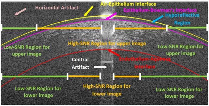
An example low-SNR corneal image (same OCT data as in Fig. 1.c) in which key regions and different types of imaging artifacts are labeled. Since SNR decreases with depth in SDOCT images, the regions of high and low-SNR also change. Some features, such as the hyporeflective region, appear in only a small subset of our corneal image database.
In a closely related problem, utilizing graph theory in retinal SDOCT segmentation has been proven successful [17–21]. The hybrid graph theory and dynamic programming retinal segmentation approach introduced by Chiu et al. has been shown to be especially flexible for handling different sources of artifacts [21].
In this paper, we use a customization of the hybrid graph theory and dynamic programming framework introduced by Chiu et al. for a fundamentally novel application that deals with unique imaging artifacts in corneal SDOCT images. Our method automatically segments three corneal layer interfaces: the epithelium-air interface (an interface between air and the tear film on the epithelium), the epithelium-Bowman’s layer interface, and the endothelium-aqueous interface as shown in Fig. 2. This robust segmentation method is capable of handling varying degrees of SNR and artifacts in corneal images. Illustrative examples of images used in our study are shown in Fig. 1 . Note that while many SDOCT corneal images have high SNR (Figs. 1a-b), low-SNR images with artifacts are not uncommon in a clinical setting (Figs. 1c-d). The anatomical features of interest, the key regions, and different types of imaging artifacts often seen in corneal SDOCT images are labeled in Fig. 2. Variable SNR in SDOCT corneal images results from differences in patient alignment, corneal hydration, tear film status, and patient motion during imaging. A central saturation artifact at the corneal apex and lower SNR in the periphery results from the telecentric (parallel) scan pattern used by most SDOCT corneal imagers. The horizontal line artifacts seen in Fig. 2 result from interaction of the central saturation artifact with the DC subtraction algorithm applied to all SDOCT A-scans. All corneal images considered in this study were obtained using OCT systems manufactured by Bioptigen, Inc. and processed with Bioptigen software (InVivoVue Clinic v1.2), although similar artifacts are observed in corneal images obtained by instruments from other vendors.
Fig. 1.
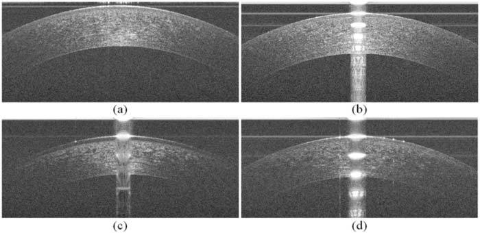
Corneal images of varying SNR and artifacts used in this study. (a) Corneal image with minimal artifacts. (b) Corneal image with prominent central and horizontal artifacts (see Fig. 2 for the visual description and annotation of these artifacts). (c) Corneal image with low-SNR, a prominent central artifact, and a hyporeflective region between the epithelium surface and the Bowman’s layer. (d) Corneal image with low-SNR, prominent central and horizontal artifacts, and other vertical artifacts.
The organization of this paper is as follows: Section 2 discusses layer segmentation using graph theory and dynamic programming, Section 3 shows an implementation of our robust algorithm for segmenting three corneal layer boundaries in images of varying quality and artifacts, Section 4 compares our automated results against expert manual segmentation, and concluding remarks are given in Section 5.
2. Review: layer segmentation using hybrid graph theory and dynamic programming
In this section, we briefly review the general framework behind graph theory and dynamic programming [21] in the context of corneal layer boundary segmentation. In this framework, images are viewed as a graph of nodes (representative of each pixel on the image) that are connected by edges, or pathways, between nodes. By assigning weights to each of the edges, the possible pathways between two nodes are given preferences. The pathway with the highest preference is then found using an appropriate dynamic programming algorithm, which generally searches for a path with the lowest cumulative weight. This resulting pathway is the segmentation, or cut, that separates the image into two meaningful regions.
To segment corneal images, we utilize the vertical intensity difference (gradient) between layers to generate edge weights that create a pathway preference along the layer boundaries as follows:
| (1) |
wab is the weight assigned to the edge connecting nodes a and b,
ga is the vertical gradient of the image at node a,
gb is the vertical gradient of the image at node b,
wmin is the minimum weight in the graph, a small positive number added for system stabilization.
In this equation, ga and gb are normalized to values between 0 and 1 with respect to the maximum and minimum gradient values within the image, and wmin = 1 × 10⁻⁵. These weights are further adjusted to account for the directionality of the gradient. To segment the air-epithelial layer boundary, for instance, it is known that the boundary consists of a darker region (air) above a brighter region (cornea), whereas the endothelial-aqueous layer boundary has a light-to-dark (cornea-to-aqueous) layer change. Thus, convolution with directional filters such as [1;-1] and [-1; 1] (MATLAB notation) can be used when calculating the gradient to extract the appropriate layers. Figure 3 shows two complementary gradient images used for calculating edge weights.
Fig. 3.

Gradient images of Fig. 1.b. (a) Dark-to-light gradient image for segmenting the air-epithelial layer boundary. (b) Light-to-dark gradient image for segmenting the endothelial-aqueous layer boundary.
It is often the case that the layer boundary to be segmented is near the presence of unrelated structures or artifacts with similar characteristics. For example, oftentimes the gradients within the stroma in the light-to-dark gradient image are of similar magnitude to the desired endothelium-aqueous interface gradient. To prevent the algorithm from segmenting these structures in place of the target feature, it is beneficial to restrict the graph to a search space that leaves out the unrelated structures. In graph theory, this means that the weights of edges that lie outside the restricted search region are removed prior to cutting the graph. For instance, after segmenting the air-epithelium boundary, we declare all nodes belonging to this boundary or regions above it as invalid, when searching for the epithelium-Bowman’s layer border. More detail in the implementation of search region limitation for corneal images follows.
3. Methods: segmentation of three corneal layer boundaries
This section details a corneal layer boundary segmentation algorithm based on the framework described in the previous section. The bulk of these modifications aim to correct for artifacts or regions of low-SNR often found in corneal SDOCT images.
The data to be segmented consists of raster scanned images of a 6 mm region of the cornea sampled by 1000 A-scans in the lateral (B-scan) dimension. Each B-scan is segmented independently from the other images within the same volume, and is assumed to be roughly centered at the apex of the cornea. Figure 4 shows an outline of our algorithm, and the following subsections discuss each of the steps.
Fig. 4.
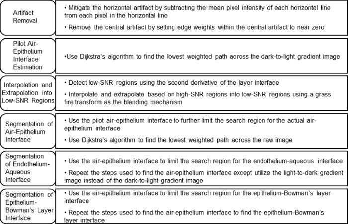
Outline of the corneal segmentation algorithm.
3.1. Artifact removal
In corneal SDOCT images, there are two main types of artifacts that often interfere with accurate automatic segmentation. We have termed these artifacts as the “central artifact” and the “horizontal artifacts”. Because these artifacts resemble or overcast corneal boundaries, diminishing their effects is essential for the success of any segmentation algorithm. As illustrated in Fig. 2, the central artifact is the vertical saturation artifact that occurs around the center of the cornea due to the back-reflections from the corneal apex, which saturates the spectrometer line camera. The periodic pattern of the central artifact is a result of the Fourier Transform utilized for reconstructing SDOCT signals. Thus, the sharp-edged saturation signals at the corneal apex appear as sinc functions in the reconstructed images. This central artifact indirectly causes the horizontal artifacts to appear due to the automatic DC subtraction algorithm implemented in the SDOCT imaging software from Bioptigen.
3.1.1. Reduction of the horizontal artifact
Rows that are corrupted by the horizontal artifact have higher mean intensities than other rows. To mitigate the horizontal artifacts within corneal images, we implemented a simple method based on reducing the DC signal in the horizontal direction. Specifically, we find the mean intensity across each row of the image and subtract it from each pixel within that row of the image. While the location of the horizontal artifacts might still be detectable via visual inspection, this subtraction significantly diminishes the horizontal artifact (and the corresponding erroneous vertical gradients) with minor changes to the anatomically relevant vertical gradients. Figure 5 below shows the processed image in Fig. 1.b once it has undergone mean intensity subtraction. Horizontal artifacts running through the cornea are not as mitigated as those above the cornea because the mean intensities of the rows intersecting the cornea include a significant amount of signal from the cornea.
Fig. 5.

Reduction of the horizontal artifact. (a) Unprocessed corneal image (Fig. 1.b). (b) Corneal image (Fig. 1.b) with mitigated horizontal artifacts due to mean intensity subtraction from each row in the image.
3.1.2. Central artifact detection & removal
The central artifact also produces unwanted gradients that affect the segmentation of corneal layer boundaries. Due to the non-uniformity of the central artifact (Figs. 1.b-d), the approach used for horizontal artifact removal is not adequate to address this problem. Thus, we implemented an alternate, yet effective way to remove the central artifact that is robust to the variations in width, relative intensity, and location of the central artifact. Our algorithm is implemented in two steps: central artifact detection followed by removal via graph weight alternation.
The key feature of the central artifact is its relatively high intensity in a selected number of neighboring vertical columns (A-scans). Among different subjects, the central artifact varies in levels of intensity, ranging from very prominent to almost nonexistent (Fig. 1.a). To detect the central artifact region, we first accentuate the central artifact by zero padding and median filtering the image with a [40x2] kernel and then search for abrupt changes in the average intensity of the neighboring A-scans. To define an abrupt change, we break the image into three equal width regions (Regions I, II, and III in Fig. 6 ) in which only the central region (Region II) is assumed to contain the central artifact. This simple ad hoc assumption has been sufficient for the 60+ volumes of corneal SDOCT data captured with our system. In order to find the central artifact in Region II, we first estimate the average intensity of the A-scans without the central artifact by calculating the average intensity (µ) of the A-scans in Regions I and III. Next, in Region II we search for the leftmost and rightmost A-scans which have average intensities greater than (4/3 × µ). We interpret the absence of an abrupt change as the lack of a central artifact, as in Fig. 1.a. The detection of the central artifact in the corneal image in Fig. 1.b can be visualized in Fig. 6, in which the plot on the bottom indicates the average A-scan intensity as a function of lateral position. Once the central artifact is detected, we nullify its effect on segmentation by reducing the weights of the edges within the central artifact to near zero. Therefore, the shortest-path would no longer be influenced by gradients within the central artifact. In Section 3.3 we attain more reliable estimates of the layer boundaries obscured by the central artifact from the neighboring regions.
Fig. 6.
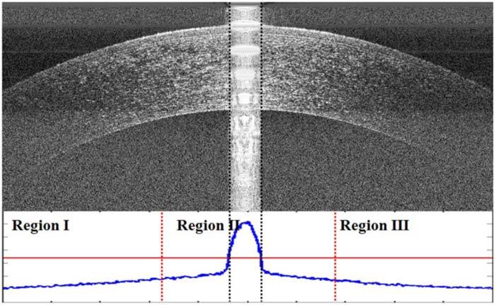
Comparison of A-scan mean intensities to detect the central artifact in Fig. 1.b. The plot below the image shows the A-scan mean intensities of the image with the different regions denoted by red, dotted vertical lines. The horizontal red line is 4/3 times the mean value of the mean intensity per A-scan in Regions I and III (the vertical axis on the bottom plot does not start at zero). The black dotted lines denote the central artifact as detected by our algorithm.
3.2. Pilot air-epithelium layer boundary estimation
After nullifying the effect of the nodes corresponding to the central artifact, we proceed to attain a pilot estimate of the air-epithelium layer boundary. We utilize Dijkstra’s method [23] and the dark-to-light weights to find the lowest-weighted path initialized at the upper left and the bottom right pixels of the image. The resulting cut is a pilot estimate of the air-epithelium layer boundary.
3.2.1. Extrapolation into low-SNR regions
In this section, we address the problem of segmenting corneal layer boundaries in regions of low-SNR (Figs. 1.c-d), which can be common in clinical settings. The pilot estimate of the epithelium layer boundary is often inaccurate in the critically low-SNR regions since the estimated image gradients (Figs. 1.c-d) are not reliable in the critically low-SNR regions of the image (Fig. 2). Thus, we determine the location of the epithelium layer boundary by extrapolating from the adjacent, more reliable high-SNR regions. In the following Subsection 3.2.2, we explain our method for detecting these low-SNR regions, and in Section 3.3 we describe the extrapolation algorithm.
3.2.2. Detection of low-SNR regions
We detect the critically low-SNR regions of the cornea, and corresponding segmentation errors, based on three a priori assumptions. Our first assumption, which is well established in previous literature [12–14], is that a second order polynomial approximates corneal layers’ two-dimensional profile. Thus with high confidence, we may assign deviations uncharacteristic of this simplified profile as outliers. Our second assumption is that Dijkstra’s algorithm in the critically low-SNR regions prefers the shortest geometric path. Our rationale for this assumption is that the corresponding weights in regions with pure noise are independent and identically distributed random variables. In such regions, the shortest geometric path between two nodes of the graph has the highest probability to accumulate the least amount of edge weights. Thus, while Dijkstra’s algorithm follows the epithelium layer curvature in the high-SNR regions, often in the critically low-SNR regions it tends to follow a straight line towards the edge of the image. Thus, we can use these deviations and detect regions of low-SNR based on points in which the erroneous pilot layer boundary experiences an abnormally positive inflection (Fig. 7 ). To exploit these two a priori assumptions, we first smooth the layer boundaries. Then, we calculate the second derivative of 40 equally distributed points, 10 in each quarter of the image, along the smoothed pilot layer boundaries to estimate large-scale inflections.
Fig. 7.
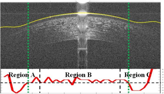
Corneal image (Fig. 1.c) with the smoothed pilot epithelial layer boundary overlaid. The second derivative plot of the pilot epithelial layer boundary is used to detect the regions of low-SNR for the epithelium excluding the center half of the image (Region B). A second derivative below 0 indicates that there is a positive inflection in the second derivative, which should not occur for normal cornea and thus indicates that the SNR may be low at this location. A second derivative below 0 in Region B often occurs near the central artifact due to the central artifact removal step which results in a linear interpolation between both sides of the central artifact.
Our third assumption is that the SNR will always be relatively high in the middle half (Region B in Fig. 7) of the image for the epithelium so we only search for low-SNR regions in the outer portions (Regions A and C in Fig. 7). Thus, for the epithelial layer boundary, we only detect positive inflections within the first and last fourths of the image. Figure 7 shows an illustrative example in which the pilot epithelial layer boundary is found and smoothed and the critically low-SNR region is correctly delineated by the dotted green lines.
3.3. Interpolation and extrapolation into low-SNR regions
In the previous subsections, we located the corneal regions with unreliable gradients; namely, the central artifact and the low-SNR regions. This subsection presents the interpolation and extrapolation strategy for determining the epithelial layer boundary in these regions. Specifically, we use the local second order polynomial model to interpolate and extrapolate in the low-SNR regions. For the left and right regions with low-SNR, the parabolic fitting functions extrapolate based on the outer halves of the left and right regions of the high-SNR region, respectively (see Fig. 2). The central artifact region was interpolated based on the inner halves of the high-SNR regions.
To create smooth junctions between the epithelial layer boundary segments, we used the grassfire transform, also known as feathering, to blend together the extrapolated/interpolated regions and the non-interpolated region [24]. The blending region consists of |β-α| pixels with the grassfire transform defined in the following formula:
| (2) |
α is the pixel from which interpolation or extrapolation begins
β is the amount of pixels from α until the pixel immediately prior to the low-SNR or central artifact region
Figure 8 illustrates the effectiveness of this technique for segmenting the epithelium layer boundary of Fig. 1.c.
Fig. 8.

Blending mechanism smoothens the transition between extrapolated and non-extrapolated segments of the image in Fig. 1.c. (a) Segmented epithelium boundary without the blending mechanism. (b) Segmented epithelium boundary with the blending mechanism.
3.4. Augmented segmentation of the air-epithelium interface
The pilot epithelium layer boundary estimate described in Section 3.2 was created based on the dark-light gradient image. This estimate does not exactly match the expert grader’s manual segmentation (see Section 4.1). Note that in corneal images, the boundary between air and epithelium appears blurry due to the point spread function (PSF) of the SDOCT system. While the gradient is most prominent in the outer boundary, the actual position of the epithelium layer boundary is the center of the bright epithelium band visualized on raw images, assuming the PSF is symmetric and that the boundary signal is bright compared to its immediate surroundings. Such disagreement is illustrated in Fig. 9.a. Therefore, we use the raw image intensities instead of gradient values for determining the graph weights in the final step of the segmentation [28]. Based on the observed spread of the PSF in the training set (see Section 4.1), the actual epithelium boundary position does not appear to vary by more than 10 µm from the pilot epithelium boundary location. Thus, to detect the actual corneal surface, we find the lowest cumulative weight path in a 20 µm wide search region centered at the pilot epithelium boundary estimate.
Fig. 9.

Mismatch between the pilot and the actual position of the epithelium layer boundary (manually segmented by a cornea specialist) in the original and dark-to-light gradient image (Fig. 1.c). (a) Pilot epithelium boundary (yellow) and the actual location of the epithelium boundary (blue) delineated over the original image. Note that the actual epithelium goes through the center of the brightest region of the original image. (b) Pilot and the actual epithelium boundary from (a) delineated on the gradient image. Note that the brightest region in the gradient image (b) is not the same as in (a), which results in mismatch between the two lines.
3.5. Segmentation of the endothelium-aqueous interface
The endothelium-aqueous interface is the second-most prominent boundary in SDOCT corneal images. Our method for segmentation for the endothelium-aqueous interface is a modified reiteration of the steps taken for the air-epithelium interface segmentation. Due to the loss of SNR in the axially lower section of the SDOCT images, the extent of the low-SNR regions across the endothelium is larger than those of the epithelium (see Fig. 2). To reduce the effects of gradients in the stroma for obtaining the pilot endothelium-aqueous interface segmentation (see Fig. 3.b), we developed a method to reduce the search region.
3.5.1. Reduction of search region for endothelium-aqueous interface
To attain a tight valid search region, we assume that the thickness of the cornea at the apex approximates the minimum thickness of the cornea. To get a more accurate measurement of the central corneal thickness, we first flatten the image based on the segmentation of the air-epithelium boundary segmentation. The flattening algorithm works by circularly shifting the positions of pixels in the image matrix according to an input vector of shift values. This can be visualized in Fig. 10 , which has the air-epithelium boundary segmentation set as the input vector.
Fig. 10.
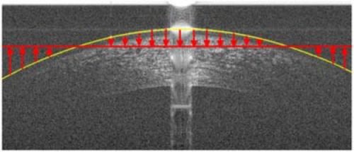
Method for flattening corneal images based on the air-epithelium boundary segmentation. The corneal image is circularly shifted either up or down depending on the position of the air-epithelium boundary segmentation in relation to the mean position of that segmentation. The red arrows indicate the direction and relative amount of the circular shift of each A-scan.
We estimate the thickness of the apex region of the cornea by estimating the vertical gradients in the Regions X and Y, which are denoted by the regions between the red, dotted lines in Fig. 11 . The central artifact generally saturates the apex region, which has the smallest thickness of the cornea. Thus, Regions X and Y were chosen to be directly to the left and right of the central artifact to best estimate the minimum corneal thickness. Within these regions, the bottom of the cornea can be found by detecting the greatest decrease in intensity, which should occur at the endothelium-aqueous interface. We chose to search for the largest decrease in the mean intensity of adjacent rows over the region 400 – 800 µm below the air-epithelium interface to avoid interference from large intensity gradients caused by the hyporeflective region as seen in Fig. 2 or other gradients in the stroma that are similar to that of the endothelium-aqueous interface (Fig. 3.b). The 400 - 800 µm search region is denoted by the green, dotted horizontal lines in Fig. 11. To increase the likelihood of detecting the bottom border of the cornea, we first denoise the region of the cornea between the red lines with a [2x20] median kernel and followed by low-pass filtering via a [5x100] Gaussian kernel with a sigma of 100 to accentuate the vertical gradients (see Fig. 11). Once the border is detected, the minimum difference between the air-epithelium interface and the detected border is used for limiting the search region for the endothelium-aqueous interface. Based on corneal thickness data from prior literature [5–7,10,11,13,14,25–27,29], our limited search region should encompass the entire range of physiologic corneal thicknesses in the central 6mm of the cornea.
Fig. 11.

Flattened version of Fig. 1.c based on air-epithelium interface. We approximate the thickness of the center of the cornea by searching for the largest decrease in mean intensity of adjacent rows within the range of 400 – 800 µm below the air-epithelium interface (green dashed line). The differences between the mean intensity of adjacent rows in central Regions X and Y are plotted in blue on the left and right of the image, respectively. Note that Regions X and Y are denoised with predominately horizontal filters to remove noise and accentual the vertical gradients.
3.6. Segmentation of the epithelium-Bowman’s layer interface
The epithelium-Bowman’s layer boundary is the third-most prominent layer boundary in SDOCT corneal images. Our method for segmentation for the epithelium-Bowman’s layer boundary is similar to the steps taken for the air-epithelium and endothelium-aqueous boundary segmentation after artifact removal. The major differences are in algorithms used for detecting the low-SNR region, the extrapolation into the low-SNR region, and the limited search region used. The low-SNR region for the epithelium-Bowman’s layer boundary is determined to be similar to that of the air-epithelium boundary (see Section 3.2.2). To extrapolate the epithelium-Bowman’s layer boundary into the low-SNR region, we go through two steps: 1) find the thicknesses of the epithelium at the border of each low-SNR region using the difference between the augmented air-epithelium boundary segmentation and the pilot epithelium-Bowman’s layer boundary and 2) maintain these thicknesses throughout the low-SNR regions on each side. Indeed, there is a thickness difference in the corneal epithelium depending on radial position (approximately a 5.9 µm thickness difference superiorly and 1.3 µm difference temporally at a 3 mm radius [29]). However, since we only extrapolate up to 1.5 mm (see Section 3.2.2), we expect that the difference between our extrapolation and the actual epithelium-Bowman’s layer boundary to be different by no more than 3–5 µm, which is approximately 1–1.5 pixels. The search region for the epithelium-Bowman’s layer interface is limited to 37–64 µm below the air-epithelium interface, which is well inclusive of the normal range of this structure as established in the literature [8,26,27]. Figure 12 shows the search region for the epithelium-Bowman’s layer interface given the air-epithelium boundary segmentation.
Fig. 12.
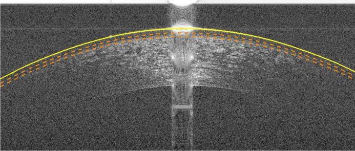
The corneal image from Fig. 1.c with the augmented air-epithelium boundary delineated in yellow. The dotted orange curves below the epithelium represent the search region for the epithelium-Bowman’s layer boundary.
4. Experimental results
4.1. Automated versus manual segmentation study
To determine the accuracy and reliability of the three corneal layer boundaries segmentation algorithm, we conducted a pilot clinical study. This study included corneal SDOCT scans from normal adult subjects, which were segmented manually by a cornea specialist and automatically using our software. To estimate manual inter-observer variability, the same images were also graded manually by a researcher trained with corneal SDOCT segmentation. To estimate manual segmentation intra-observer repeatability, each manual grader segmented each image twice without being aware of the duplication.
The data set was created by randomly selecting 20 B-scans from a pool of 60 OCT corneal volumes. These 60 corneal volumes were taken under an IRB approved protocol by imaging in triplicate both eyes of 10 normal adult subjects using a Bioptigen (Research Triangle Park, NC) SDOCT imaging system fitted with a corneal adapter. This commercial system had a measured peak sensitivity of 104 dB at 50 ms acquisition time per B-scan, an axial resolution of 4.3 µm full-width at half-maximum in tissue, and the corneal adapter enabled an essentially telecentric (parallel) sample arm beam scan pattern across the cornea. All subjects were represented in the final data set, and no volume was represented by more than one B-scan. Each volume consisted of 50 radial B-scans, 1000 A-scans each, and 1024 axial pixels per A-scan. The nominal scan width was 6 mm. The measured B-scan pixel sampling resolution in tissue was 6.1 µm (lateral) x 4.6 µm (axial). The randomly selected 20-frame test data set was duplicated for the repeatability test and then randomly shuffled to create the final 40-frame test data set. The automatic segmentation algorithm parameters were selected based on a training set of five frames, which did not include images from the 40-frame test data set described above.
Within the 20 original frames of the test data set, 17 frames had low-SNR regions for the air-epithelium interface, 19 frames had low-SNR regions for the epithelium-Bowman’s interface, and all 20 frames had low-SNR regions for the endothelium-aqueous interface. From the frames that had regions of low-SNR, the average number of A-scans with low SNR was 134 A-scans for the air-epithelium interface, 211 A-scans for the epithelium-Bowman’s layer interface, and 389 A-scans for the endothelium-aqueous layer interface with standard deviations of 68, 117, and 97 A-scans, respectively. The central and horizontal artifacts were prominent in 18 frames with an average width of 77 A-scans and a standard deviation of 23 A-scans. The number of A-scans in the low-SNR and central artifact regions corresponds to the number of columns detected within those regions by our algorithm.
The three corneal layer boundaries were segmented automatically on the 40-frame test data set using a MATLAB implementation of our algorithm. The average computation time was 1.13 seconds per image after implementing parallel processing with 8 threads (64-bit OS, Intel (R) Core (TM) i7 CPU 860 at 2.80 GHz and 16 GB RAM). The three layer boundaries were independently, manually traced by the two graders on the same test data set.
We calculated the difference in layer boundary position between the manual graders and the automatic segmentation software for each B-scan. The same was done to compare the two manual graders. The absolute mean and standard deviation of these differences across all B-scans were calculated and are shown in Table 1 . Column I shows the absolute average pixel difference for the three corneal layers as measured by two manual graders. Column II displays the layer boundary difference between the automatic segmentation software and the expert grader.
Table 1. Differences in corneal layer boundary segmentation between two manual graders for 40 B-scans (Column I), as compared to the position differences between the automatic segmentation and the expert manual grader of the same 40 B-scans (Column II). Each pixel is approximately 3.4 µm in the cornea. The automatic segmentation has the same or lower mean difference and standard deviation compared to the expert than another trained manual grader.
| |
Comparison of Two Manual Graders |
Comparison of Automatic
and Manual Expert Segmentation |
||
|---|---|---|---|---|
| |
Column I |
Column II |
||
| Corneal Layer Boundary | Mean Difference (pixels) | Standard Deviation (pixels) | Mean Difference (pixels) | Standard Deviation (pixels) |
| Epithelium-Air Interface | 1.5 | 0.4 | 0.6 | 0.4 |
| Epithelium-Bowman Interface | 1.2 | 0.5 | 0.9 | 0.5 |
| Endothelium-Aqueous Interface | 2.1 | 2.3 | 1.7 | 2.1 |
The results in Table 1 show that the automatic algorithm segmented three corneal layer boundaries in normal adult eyes more closely to an expert grader as compared to a trained manual grader. Figure 13 displays the qualitative results, with the automatic segmentation (cyan) and trained manual segmentation (green) overlaid with the expert segmentation (magenta) results.
Fig. 13.

(a) Comparison of automatic (cyan) versus expert (magenta) segmentation. (b) Comparison of trained manual (green) versus expert (magenta) segmentation.
Due to the low SNR of some corneal images, the variation between segmentations of the individual graders was significant. Thus, we conducted a repeatability test in which the results are displayed in Table 2 . Column I shows the intra-observer repeatability of the first expert manual grader and Column II displays the intra-observer repeatability of the second trained manual grader.
Table 2. Repeatability tests for the First Expert Manual Grader (Column I) and the Second Trained Manual Grader (Column II). Each pixel is approximately 3.4 µm in the cornea.
| |
Comparison of First Expert
Manual Grader to Self |
Comparison of Second Trained
Manual Grader to Self |
||
|---|---|---|---|---|
| |
Column I |
Column II |
||
| Corneal Layer Boundary | Mean Difference (pixels) | Standard Deviation (pixels) | Mean Difference (pixels) | Standard Deviation (pixels) |
| Epithelium-Air Interface | 0.5 | 0.2 | 1.2 | 0.8 |
| Epithelium-Bowman Interface | 0.8 | 0.4 | 1.1 | 0.9 |
| Endothelium-Aqueous Interface | 1.5 | 2.3 | 2.5 | 3.0 |
For corneal images of varying degrees of SNR and artifacts shown in Fig. 1, the results of our robust segmentation are shown in Fig. 14 .
Fig. 14.
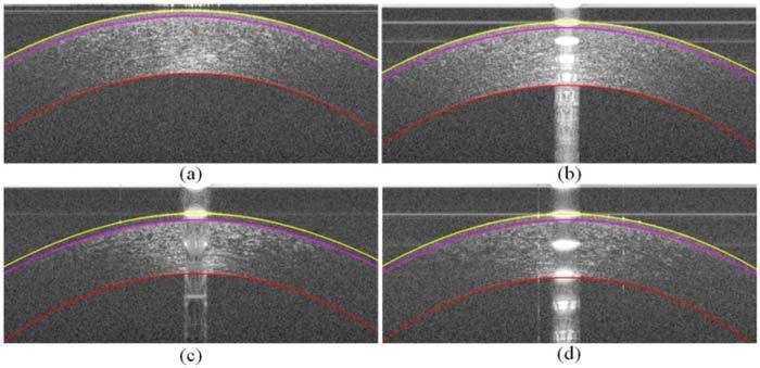
a–d) The segmented corneal images of Fig. 1.a–d, respectively, in which the yellow layer is the air-epithelium interface, the magenta layer is the epithelium-Bowman’s layer interface, and the red layer is the endothelium-aqueous interface. Recall from Fig. 1 that (a) and (b) had relatively high-SNR and (c) and (d) had relatively low-SNR.
4.2. Other segmentation results
Sections 3 and 4.1 discuss the algorithm implemented for segmenting corneal layers on normal adult SDOCT images. As seen in Fig. 15 , the general graph theory and dynamic programming paradigm for segmenting layered structures extends to non-normal corneal images as well. Four layer boundaries segmentation for an eye with a LASIK flap is shown in Fig. 15.a. Three layer boundaries segmentation for an eye with abnormally steep curvatures (keratoconus) is shown in Fig. 15.b. These are illustrative examples; the extension and quantitative validation of our algorithm for non-normal corneal will be presented in future work.
Fig. 15.

Segmentation of a cornea that has undergone LASIK surgery and a cornea with keratoconus. (a) Cornea after LASIK surgery with four layer interfaces segmented: the air-epithelium layer interface (yellow), the epithelium-Bowman’s layer interface (magenta), the LASIK flap (cyan), and the endothelium-aqueous interface (red). (b) Cornea with keratoconus with the yellow, magenta, and red curves representing the same interfaces as in (a).
5. Conclusion
In this work, we presented an automatic method for accurate segmentation of three clinically important corneal layer boundaries on SDOCT images of normal eyes. Our algorithm is robust against artifacts and low-SNR regions often seen in clinical SDOCT images. Compared to an expert grader, our automatic segmentation algorithm more closely and consistently matched the expert segmentation compared to a second trained manual grader.
While this work was done serially on two-dimensional B-scan images, it is possible to extend this work to three-dimensional volumetric segmentation. Three-dimensional volumetric segmentation would introduce additional information from neighboring voxels, which may further improve segmentation accuracy, though likely with increased computation costs.
Our work, as presented, is promising for reducing the time, manpower, and costs required for accurately segmenting and analyzing corneal SDOCT images. This will allow for practical, large-scale introduction of corneal SDOCT into the clinical patient care setting.
Acknowledgments
This work was supported in part by the Duke Pratt Fellowship Program (FL), the Duke Grand Challenge Scholars Program (FL), NIH grants K12-EY01633305 (ANK) and R21-EY020001 (RPM, ANK, JAI), the Research to Prevent Blindness unrestricted funds (SF), and the Wallace H. Coulter Translational Partners Grant Program (RPM, ANK, JAI).
References and links
- 1.Huang D., Swanson E. A., Lin C. P., Schuman J. S., Stinson W. G., Chang W., Hee M. R., Flotte T., Gregory K., Puliafito C. A., Fujimoto J. G., “Optical coherence tomography,” Science 254(5035), 1178–1181 (1991). 10.1126/science.1957169 [DOI] [PMC free article] [PubMed] [Google Scholar]
- 2.Fujimoto J. G., Drexler W., Schuman J. S., Hitzenberger C. K., “Optical Coherence Tomography (OCT) in ophthalmology: introduction,” Opt. Express 17(5), 3978–3979 (2009). 10.1364/OE.17.003978 [DOI] [PMC free article] [PubMed] [Google Scholar]
- 3.Izatt J. A., Hee M. R., Swanson E. A., Lin C. P., Huang D., Schuman J. S., Puliafito C. A., Fujimoto J. G., “Micrometer-scale resolution imaging of the anterior eye in vivo with optical coherence tomography,” Arch. Ophthalmol. 112(12), 1584–1589 (1994). [DOI] [PubMed] [Google Scholar]
- 4.Radhakrishnan S., Rollins A. M., Roth J. E., Yazdanfar S., Westphal V., Bardenstein D. S., Izatt J. A., “Real-time optical coherence tomography of the anterior segment at 1310 nm,” Arch. Ophthalmol. 119(8), 1179–1185 (2001). [DOI] [PubMed] [Google Scholar]
- 5.Morad Y., Sharon E., Hefetz L., Nemet P., “Corneal thickness and curvature in normal-tension glaucoma,” Am. J. Ophthalmol. 125(2), 164–168 (1998). 10.1016/S0002-9394(99)80086-5 [DOI] [PubMed] [Google Scholar]
- 6.Liu Z., Pflugfelder S. C., “The effects of long-term contact lens wear on corneal thickness, curvature, and surface regularity,” Ophthalmology 107(1), 105–111 (2000). 10.1016/S0161-6420(99)00027-5 [DOI] [PubMed] [Google Scholar]
- 7.Liu Z., Huang A. J., Pflugfelder S. C., “Evaluation of corneal thickness and topography in normal eyes using the Orbscan corneal topography system,” Br. J. Ophthalmol. 83(7), 774–778 (1999). 10.1136/bjo.83.7.774 [DOI] [PMC free article] [PubMed] [Google Scholar]
- 8.Müller L. J., Pels E., Vrensen G. F. J. M., “The specific architecture of the anterior stroma accounts for maintenance of corneal curvature,” Br. J. Ophthalmol. 85(4), 437–443 (2001). 10.1136/bjo.85.4.437 [DOI] [PMC free article] [PubMed] [Google Scholar]
- 9.Seitz B., Torres F., Langenbucher A., Behrens A., Suárez E., “Posterior corneal curvature changes after myopic laser in situ keratomileusis,” Ophthalmology 108(4), 666–672, discussion 673 (2001). 10.1016/S0161-6420(00)00581-9 [DOI] [PubMed] [Google Scholar]
- 10.Shimmyo M., Ross A. J., Moy A., Mostafavi R., “Intraocular pressure, Goldmann applanation tension, corneal thickness, and corneal curvature in Caucasians, Asians, Hispanics, and African Americans,” Am. J. Ophthalmol. 136(4), 603–613 (2003). 10.1016/S0002-9394(03)00424-0 [DOI] [PubMed] [Google Scholar]
- 11.Kohlhaas M., Boehm A. G., Spoerl E., Pürsten A., Grein H. J., Pillunat L. E., “Effect of central corneal thickness, corneal curvature, and axial length on applanation tonometry,” Arch. Ophthalmol. 124(4), 471–476 (2006). 10.1001/archopht.124.4.471 [DOI] [PubMed] [Google Scholar]
- 12.Li Y., Shekhar R., Huang D., “Segmentation of 830- and 1310-nm LASIK corneal optical coherence tomography images,” Proc. SPIE 4684, 167–178 (2002). 10.1117/12.467123 [DOI] [Google Scholar]
- 13.Li Y., Shekhar R., Huang D., “Corneal pachymetry mapping with high-speed optical coherence tomography,” Ophthalmology 113(5), 792–799.e2 (2006). 10.1016/j.ophtha.2006.01.048 [DOI] [PMC free article] [PubMed] [Google Scholar]
- 14.Li Y., Netto M. V., Shekhar R., Krueger R. R., Huang D., “A longitudinal study of LASIK flap and stromal thickness with high-speed optical coherence tomography,” Ophthalmology 114(6), 1124–1132e1 (2007). 10.1016/j.ophtha.2006.09.031 [DOI] [PubMed] [Google Scholar]
- 15.J. A. Eichel, A. K. Mishra, D. A. Clausi, P. W. Fieguth, and K. K. Bizheva, “A novel algorithm for extraction of the layers of the cornea,” in Canadian Conference on Computer and Robot Vision, 2009. CRV '09 (IEEE, 2009), pp. 313–320. [Google Scholar]
- 16.Hutchings N., Simpson T. L., Hyun C., Moayed A. A., Hariri S., Sorbara L., Bizheva K., “Swelling of the human cornea revealed by high-speed, ultrahigh-resolution optical coherence tomography,” Invest. Ophthalmol. Vis. Sci. 51(9), 4579–4584 (2010). 10.1167/iovs.09-4676 [DOI] [PubMed] [Google Scholar]
- 17.Haeker M., Sonka M., Kardon R., Shah V. A., Wu X., Abramoff M. D., “Automated segmentation of intraretinal layers from macular optical coherence tomography images,” Proc. SPIE 6512, 651214 (2007). 10.1117/12.710231 [DOI] [Google Scholar]
- 18.Garvin M. K., Abràmoff M. D., Wu X., Russell S. R., Burns T. L., Sonka M., “Automated 3-D intraretinal layer segmentation of macular spectral-domain optical coherence tomography images,” IEEE Trans. Med. Imaging 28(9), 1436–1447 (2009). 10.1109/TMI.2009.2016958 [DOI] [PMC free article] [PubMed] [Google Scholar]
- 19.Lee K., Niemeijer M., Garvin M. K., Kwon Y. H., Sonka M., Abramoff M. D., “Segmentation of the optic disc in 3-D OCT scans of the optic nerve head,” IEEE Trans. Med. Imaging 29(1), 159–168 (2010). 10.1109/TMI.2009.2031324 [DOI] [PMC free article] [PubMed] [Google Scholar]
- 20.Tolliver D. A., Koutis I., Ishikawa H., Schuman J. S., Miller G. L., “Automatic multiple retinal layer segmentation in spectral domain OCT scans via spectral rounding,” Invest. Ophthalmol. Vis. Sci. 49, 1878-2222 (2008). [Google Scholar]
- 21.Chiu S. J., Li X. T., Nicholas P., Toth C. A., Izatt J. A., Farsiu S., “Automatic segmentation of seven retinal layers in SDOCT images congruent with expert manual segmentation,” Opt. Express 18(18), 19413–19428 (2010). 10.1364/OE.18.019413 [DOI] [PMC free article] [PubMed] [Google Scholar]
- 22.Zhao M., Kuo A. N., Izatt J. A., “3D refraction correction and extraction of clinical parameters from spectral domain optical coherence tomography of the cornea,” Opt. Express 18(9), 8923–8936 (2010). 10.1364/OE.18.008923 [DOI] [PubMed] [Google Scholar]
- 23.Dijkstra E. W., “A note on two problems in connexion with graphs,” Numer. Math. 1(1), 269–271 (1959). 10.1007/BF01386390 [DOI] [Google Scholar]
- 24.Szeliski R., “Image alignment and stitching: a tutorial,” Found. Trends Comput. Graphics Vision 2(1), 1–104 (2006). 10.1561/0600000009 [DOI] [Google Scholar]
- 25.Herndon L. W., Choudhri S. A., Cox T., Damji K. F., Shields M. B., Allingham R. R., “Central corneal thickness in normal, glaucomatous, and ocular hypertensive eyes,” Arch. Ophthalmol. 115(9), 1137–1141 (1997). [DOI] [PubMed] [Google Scholar]
- 26.Li H. F., Petroll W. M., Møller-Pedersen T., Maurer J. K., Cavanagh H. D., Jester J. V., “Epithelial and corneal thickness measurements by in vivo confocal microscopy through focusing (CMTF),” Curr. Eye Res. 16(3), 214–221 (1997). 10.1076/ceyr.16.3.214.15412 [DOI] [PubMed] [Google Scholar]
- 27.Reinstein D. Z., Silverman R. H., Rondeau M. J., Coleman D. J., “Epithelial and corneal thickness measurements by high-frequency ultrasound digital signal processing,” Ophthalmology 101(1), 140–146 (1994). [DOI] [PubMed] [Google Scholar]
- 28.Schuman S. G., Koreishi A. F., Farsiu S., Jung S. H., Izatt J. A., Toth C. A., “Photoreceptor layer thinning over drusen in eyes with age-related macular degeneration imaged in vivo with spectral-domain optical coherence tomography,” Ophthalmology 116(3), 488–496e2 (2009). 10.1016/j.ophtha.2008.10.006 [DOI] [PMC free article] [PubMed] [Google Scholar]
- 29.Reinstein D. Z., Archer T. J., Gobbe M., Silverman R. H., Coleman D. J., “Epithelial thickness in the normal cornea: three-dimensional display with Artemis very high-frequency digital ultrasound,” J. Refract. Surg. 24(6), 571–581 (2008). [DOI] [PMC free article] [PubMed] [Google Scholar]


