

Abstract
The activation of well-defined numbers of integrin molecules in predefined areas by adhesion of tissue cells to biofunctionalized micro-nanopatterned surfaces was used to determine the minimum number of activated integrins necessary to stimulate focal adhesion formation. This was realized by combining micellar and conventional e-beam lithography, which enabled deposition of 6 nm large gold nanoparticles on predefined geometries. Patterns with a lateral spacing of 58 nm and a number of gold nanoparticles, ranging from 6 to 3000 per adhesive patch, were used. For αv β3-integrin activation, gold nanoparticles were coated with c(-RGDfK-)-thiol peptides, and the remaining glass surface was passivated to prevent non-specific protein adsorption and cell adhesion. Results show that focal adhesion formation is dictated by the underlying hierarchical nanopattern. Adhesive patches with side lengths of 3000 nm and separated by 3000 nm, or with side lengths of 1000 nm and separated by 1000 nm, containing approximately 3007 ± 193 or 335 ± 65 adhesive gold nanoparticles, respectively, induced the formation of actin-associated, paxillin-rich focal adhesions, comparable in size and shape to classical focal adhesions. In contrast, adhesive patches with side lengths of 500, 250 or 100 nm, and separated from adjacent adhesive patches by their respective side lengths, containing 83 ± 11, 30 ± 4, or 6 ± 1 adhesive gold nanoparticles, respectively, showed a significant increase in paxillin domain length, caused by bridging the pattern gap through an actin bundle in order to mechanically, synergistically strengthen each single adhesion site. Neither paxillin accumulation nor adhesion formation was induced if less than 6 c(-RGDfK-)-thiol functionalised gold nanoparticles per adhesion site were presented to cells.
Introduction
Cell–cell and cell–extracellular matrix (ECM) adhesion sites entail complex, highly regulated processes, and play a crucial role in most fundamental cellular functions, including motility, proliferation, differentiation and apoptosis.1,2 Understanding the molecular basis of adhesion processes is therefore essential, in order to disentangle the complex environmental cues regulating cellular functions.
The primary structures involved in cell–ECM adhesions are focal adhesions (FAs), consisting of integrins, transmembrane adhesion receptors, and cytoplasmic “anchor proteins” such as vinculin, talin and paxillin which bind the actin cytoskeleton to the membrane.3–9 The binding of cells to ECM molecules induces local accumulation of these proteins, and their subsequent assembly into a well-organized adhesion site.10 The importance of the structural organization of FAs on a molecular length scale has been demonstrated by investigations of cellular responses to differences in the lateral spacing of adhesion-associated ligands.11–14 However, studies concerning the existence of hierarchical and cooperative arrangements, and synergistic interactions between FA proteins, are still poorly characterized. In particular, the significance of the size and shape of FAs for cell signaling, as well as the nano-scale protein topology within these adhesion sites, is not yet understood. As a consequence, current experiments in this field are directed towards identifying the geometrical architectures of biocompatible adhesive surfaces, which initiate and guide FA formation, as well as molecular connections between adjacent adhesion sites. These studies are based on biofunctionalized, synthetic micro- to nanostructured interfaces, which rigorously control the location and amount of activated integrins in defined sites where FA assembly is initiated.
A key step in FA assembly entails the clustering of integrins, following their external stimulation by immobile ECM ligands. These clusters consist of non-covalently bound integrin α- and β-subunits, both of which recognize the RGD (arginine–glycine–aspartate) ligand, a sequence present in many ECM proteins. However, it remains unclear to what extent cell adhesion and cell signaling are regulated by the molecular architecture of FAs; i.e., their geometry, integrin-to-integrin spacing, and number of activated proteins. Specifically, it is not yet known how many adhesive sites for single integrin activation are necessary, to trigger the formation of stable cell adhesion sites and associated signaling events.15
Fabricated nanopatterned adhesive sites that control the arrangement of FA clusters on a molecular scale may offer insights into many issues concerning FA assembly and surface sensing at integrin adhesion sites.11,16 Thus far, the fabrication of “nano-digital surfaces,” extended areas within which the number and positions of ECM epitopes are precisely defined, is not yet reality. Indeed, techniques such as microcontact printing or dip-pen lithography17 enable the decoration of surfaces with adhesive islands on a submicrometre-sized substrate (<100 nm), yet they fail to provide information regarding the precise number of ECM ligands available at surfaces. Consequently, such techniques cannot control local ECM-ligand concentrations—i.e., ligand-to-ligand spacing, and the number of ligands presented per site—with molecular precision. Micellar diblock copolymer lithography, for example, enables the organization of well-defined biofunctionalized gold nanoparticles in a quasi-hexagonal pattern. The diameter of the gold particles can be varied from 1–15 nm, independent of the lateral spacing. The latter can be varied from 15 to 250 nm by modifying either the molecular weight of the diblock copolymer, or the speed at which the surface scaffold is withdrawn from the micelle solution.16,18,19 In conjunction with electron-beam or photo-lithography, substrates with a defined number of gold nanoparticles, i.e., from one to several hundreds of gold nanoparticles per site, can be organized.18,20,21 Biofunctionalization of these nanostructured interfaces with intact ECM molecules or adhesive peptides, enables the probing of single transmembrane receptors through interactions of cells with the interfaces.22 Binding of only a single transmembrane protein per individual gold nanoparticle is ensured by the restricted surface area offered by the nanoparticle. A nanoparticle diameter of 6 nm is smaller than the diameter of an integrin molecule, which is approximately 10 nm.23 The functionalization of a 6 nm-sized nanoparticle with c(-RGDfK-)-thiol peptides24 at a predefined location offers an adhesive patch of approximately 8 nm,11,16 enabling the immobilization and activation of individual integrin molecules at defined sites on a substrate.25
Results and discussion
The successful functionalization of each gold nanoparticle by c(-RGDfK-)-thiol peptides is evidenced by scanning force microscopy data as shown in the ESI (Fig. S1).† Cell adhesion to patterns on tailored, biofunctionalized surface patterns was investigated by means of phase contrast, fluorescence and scanning electron microscopy. Block copolymer micelle nanolithography (BCML) was used to generate a range of gold nanoparticle arrays in pattern fields on glass cover slips. Each pattern field was either 50 × 50 μm2 or 100 × 100 μm2 in size (Fig. 1A–C). Patterns were generated as squares with the following side lengths: 3000 nm (Fig. 1D), 1000 nm (Fig. 1E), 500 nm (Fig. 1F), 250 nm (Fig. 1G), and 100 nm (Fig. 1H). The squares were separated by their respective side lengths, in order to maintain a constant particle density in each pattern field. The spacing of the nanoparticles within the squares was kept at ~58 nm, since FA formation is observed for such a spatial confinements of integrins.11,14,16
Fig. 1.

A typical substrate design of hierarchically patterned substrates: (A) a schematic drawing of the substrate design. (B) A SE micrograph of the pattern fields: each field has a side length of approximately 100 μm. (C) A phase-contrast micrograph of REF52 cells plated for 3 h on hierarchical patterns shown in (B). (D) A close-up of the pattern field containing 3000 nm large squares, separated by 3000 nm. (E)–(H) Gold nanoparticles arranged on 1000 nm, 500 nm, 250 nm and 100 nm squares. The number in the top right corner corresponds to the numbers given in (B) and (C). (I) A schematic for the biofunctionalization of interfaces for single integrin activation.
The substrates were functionalized in two steps (Fig. 1I). The principle behind this method of biofunctionalization was previously reported.11,22 In brief, areas between the gold particles were passivated to eliminate non-specific protein adsorption, by first coupling poly(ethylene glycol) (PEG)-terminated siloxanes to the SiOH-groups of the glass. The gold particles were then functionalized with c(-RGDfK-)-thiols, including the cell-adhesive RGD sequence. As a control for successful passivation of the substrate, cell-adhesion experiments were performed, either by functionalizing the nanostructures with c(-RGE-)-thiol peptides, or with no peptide functionalization at all. Previous studies reported that RGE peptides fail to activate integrin-associated adhesions.26 Indeed, no adhesive interactions were noted on either of these surfaces, confirming that the adhesion formation as reported herein is entirely due to the activation of αv β3-integrin by the c(-RGDfK-)-thiols.
In order to evaluate FA formation on micro-nanostructured adhesive islands, REF52-YFP-paxillin cells (embryonic rat cells transfected to express yellow fluorescent protein) were plated for up to 4 h in DMEM containing 1% FBS (see Materials and methods for details). Live cell imaging was performed on a fluorescence microscope equipped with a temperature-, CO2-, and humidity-controlled environmental chamber. Typically, the cells began spreading after approximately 30 min.
Fig. 2A shows a typical cell, plated for 2 h on a patterned field of 50 μm × 50 μm, consisting of 500 nm × 500 nm nanopatterned squares separated by 500 nm (pattern #3 in Fig. 1). The imaged cell spread to the borders of the pattern field. Accumulation of paxillin—a FA-associated protein—in these squares of 500 nm × 500 nm indicates the guidance of FA geometry on the adhesive nanopatterned squares. Paxillin accumulation is predominantly found in the corners and along the four edges of the pattern field. Fig. 2B presents a magnified view of the top right corner of the pattern field, illustrating the defined arrangement of the adhesion sites along the adhesive nanopatterned squares. The spatial modulation of the paxillin fluorescence intensity mainly follows the sites of the nanoparticles functionalized with c(-RGDfK-)-thiols. Only between the center and periphery of cell streaks of paxillin may be identified which do not correlate ideally with the c(-RGDfK-)-thiol functionalized pattern. These are moving paxillin accumulations which dynamically appear and disappear as observed by live cell optical microscopy and do not correspond to mature focal adhesions as observed at the cell edges. The paxillin fluorescence intensity distribution is shown in Fig. 2C, indicating its non-homogenous nature within the adhesion sites.
Fig. 2.
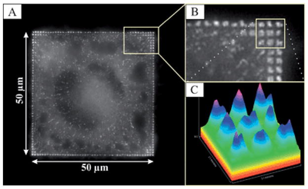
(A) A live cell fluorescence microscopy image of a REF52-YFP-paxillin cell plated for 2 h on a 50 μm square divided into 500 × 500 nm squares, separated by 500 nm. (B) A close-up of (A), illustrating the contact site formation on such squares. (C) The paxillin fluorescence intensity distribution on cellular adhesion sites.
In Fig. 3, the total ligand density remained constant, while the side lengths of the adhesive nanopatterned squares varied from 100 nm to 3 μm, providing defined numbers of c(-RGDfK-)-thiol functionalized nanoparticles ranging from 6 to ~3000 per individual square. The spacing between gold particles on each nanopatterned square was ~58 nm. Assuming the number of particles on the substrate to be constant but being distributed homogeneously over the substrate area and not to be confined in microsized domains, a particle spacing of 116 nm would be necessary to obtain this. This finding is important, because it has been shown that REF52-YFP-paxillin cells cannot obtain stable adhesion on substrates with homogeneous particle spacings of greater than 58 nm.11 In these studies, REF52-YFP-paxillin cells were plated for 3 h. Cell-substrate contacts were analyzed by visualizing fluorescently labeled actin and paxillin with fluorescence microscopy or scanning electron microscopy. All cells plated on the structured areas were able to adhere and spread only on the nanopatterned part of the substrate. These plated cells formed distinct, paxillin-rich FA sites on the substrate; the distribution of FA sites was found to be highly dependent upon the underlying patterns. Cells adhering to patterns of 3 μm and 1 μm squares (Fig. 3, rows A and B) formed FA with lengths of approximately the size of the adhesive squares; i.e., 2.7 ± 0.7 μm and 0.9 ± 0.1 μm, respectively (Table 1). In these cases, each FA was associated with several (3 μm squares; Fig. 3, row A) or just one defined actin bundle (1 μm squares; Fig. 3, row B). In contrast, smaller adhesive islands such as those that formed on the adhesive nanopatterned squares with side lengths of 500 nm or 250 nm were linked to several adjacent, paxillin-rich domains by the same actin bundle (Fig. 3, rows C and D). The actin bundle clearly bridges across the non-adhesive areas. The total length of these connected adjacent paxillin domains (actin-connected paxillin domain length) has a mean value of 3.5 ± 0.7 μm for the 500 nm squares, and 2.9 ± 1.1 μm for the 250 nm squares (Table 1). In the case of 100 nm × 100 nm adhesive nanopatterned squares separated by 100 nm (Fig. 3, row E), the restriction of paxillin accumulation to individual squares could not be resolved by optical microscopy. However, the total length of the connected paxillin domains was measured at 4.7 ± 2.3 μm (Table 1). This measurement is comparable to the value obtained on extended homogeneous nanoparticle arrays with the same 58 nm spacing (4.8 ± 2.2 μm; see Table 1, and Fig. 3, row F). The scanning electron micrographs in Fig. 3 show the cells’ adhesive contacts with the nanopattern at a slightly higher resolution. However, only the arrangement of the cell membrane relative to the nanopattern can be discerned. Further insights into molecular organization of FAs will likely be provided by future electron microscopy studies.
Fig. 3.

Close-ups of FA and cytoskeleton formation of REF52-YFP-paxillin cells plated for 3 h on hierarchically structured nanopatterns. Side lengths of squares: 3000 nm (row A), 1000 nm (row B), 500 nm (row C), 250 nm (row D), 100 nm (row E) and an extended nanopattern (row F). The cells were either fixed and fluorescently stained on glass substrates (columns 3) or fixed and critical point dried on silicon wafers (columns 4 and 5) on the respective patterns. The red lines and the yellow squares in column 3 highlight the positions of each adhesive patch. FA size is restricted by the underlying pattern geometry if patch sizes are 3 μm or 1 μm, as indicated by the red arrow in A1. On patch sizes ≤500 nm, adjacent paxillin domains are bridged by an overlying actin fiber, see the red arrow in C1. The borders between neighboring paxillin sites are blurred due to the spatial resolution of optical microscopy.
Table 1.
Pattern characteristics and actin-connected paxillin domain length
| Substrate pattern | Functionalized gold particles per adhesive patch | Actin-connected paxillin domain length/μm |
|---|---|---|
| 100 nm squares separated by 100 nm | 6 ± 1 | 4.7 ± 2.3 |
| 250 nm squares separated by 250 nm | 30 ± 4 | 2.9 ± 1.1 |
| 500 nm squares separated by 500 nm | 83 ± 11 | 3.5 ± 0.7 |
| 1000 nm squares separated by 1000 nm | 335 ± 64 | 0.9 ± 0.1 |
| 3000 nm squares separated by 3000 nm | 3007 ± 193 | 2.7 ± 0.7 |
| Extended homogeneous 58 nm gold nanoparticle pattern | — | 4.8 ± 2.2 |
Our current data show that cells have a tendency to extend paxillin domains. The length of paxillin domains is associated with the force applied to the adhesion site through actin bundle contraction27 during cell spreading and migration. We speculate that when cells are plated on adhesive patches comprising squares of 3000 nm or 1000 nm side lengths, each separate adhesive site is still sufficiently mature to withstand the applied load per patch necessary for cell spreading (Fig. 3, rows A and B). In contrast, cells couple to adjacent paxillin domains through a single actin bundle if adhesive squares are ≤500 nm, in order to mechanically stabilize adhesion and thereby enable the cells to spread. These observations further indicate that if cell adhesion is to occur a distinct number of integrins must cluster together and couple via actin filaments in order to stabilize adhesion. Table 1 summarizes the lengths of paxillin domains according to patch size, and correlates them to the number of functionalized gold nanoparticles, which equals the maximum number of activated integrins per patch. A minimum of 6 biofunctionalized nanoparticles per adhesive patch, each patch being separated by approximately 100 nm, was found to be the minimal number in order to activate cell adhesion, paxillin accumulation and consequent FA formation. Fewer nanoparticles per site did not result in paxillin accumulation. Fig. 4 presents scanning electron microscopic images at even higher resolution, in which the contact of single cell protrusions with single biofunctionalized gold nanoparticles of 6 nm size may be seen. Fig. 5 plots the length of connected paxillin domains as a function of square size for the different pattern fields, including the extended nanopattern substrate with a nanoparticle spacing of 58 nm.
Fig. 4.

(A) A phase-contrast micrograph of a fixed REF52 cell plated for 24 h on extended patterned interfaces including 6 nm-sized gold nanoparticles with lateral spacings of ~58 nm. (B)–(D) Scanning electron micrographs show parts of cells on such biofunctionalized extended nanopatterns. The inset in (C) shows a close-up view of ultra-small cellular protrusions with diameters of 10–20 nm, and lengths of 30–50 nm, interacting with the activated gold nanoparticles. (D) SEM image, recorded with a tilt angle of 40°, depicting ultra-small cellular protrusions interacting with the c(-RGDfk-) adhesion sites. (E)–(G) Scanning electron micrographs of filopodial structures on biofunctionalized hierarchical nanopatterns (500 nm squares separated by 1000 nm, tilt angle 45°). The white arrow indicates an early filopodial structure, including its bending (indicated by the yellow arrow), red arrows indicate mature contact structures, and blue arrows show ultra-small cellular protrusions in contact with the adhesive gold nanoparticles.
Fig. 5.

The length of actin-connected paxillin domains on different pattern fields: (A) 3 × 3 μm2), (B) 1 × 1 μm2, (C) 0.5 × 0.5 μm 2, (D) 0.25 × 0.25 μm2, and (E) 0.1 × 0.1 μm2, compared to (F) an extended nanopatterned substrate, with interparticle spacings of 58 nm.
Materials and methods
Preparation of nanostructured glass and silicon interfaces
Glass coverslips (20 × 20 mm, Carl Roth & Co GmbH, Karlsruhe, Germany) or silicon wafers (CrysTec GmbH, Berlin, Germany) were cleaned with a mixture of 3/4 conc. H2SO4 and 1/4 H2O2 (35%) for at least 30 min., rinsed extensively with MilliQ water (R ≥18 MΩ), and then dried under a stream of nitrogen. The oxidation of all adsorbed organic compounds led to a clean and highly hydrophilic surface (Θ < 4°).
Preparation of micro-nanopatterned substrates
Polymeric gold-ion-loaded micellar solutions were prepared with polystyrene(500)-block-poly(2-vinylpyridine)(270) (Polymer Source Inc., City, Canada), as previously described.21 Freshly cleaned silicon wafer or carbon thread coated glass coverslips were coated with a monomicellar film by dipping them in a solution with gold-loaded micelles, and then irradiating them with an electron beam. An acceleration voltage of 1 or 2 kV, and a dose of 7.500 μC cm−2 or 15.000 μC cm−2, respectively, were applied. Electron beam lithography was carried out by means of an LEO 1530 or a Zeiss Ultra 55 field emission scanning electron microscope (FE-SEM) equipped with an Elphy Plus electron beam lithography unit (Raith GmbH, Dortmund, Germany) as previously described.19
Pre-treatment of the biofunctionalized substrate
To prevent non-specific adsorption to the glass surface, substrates were treated with mPEG-triethoxysilanes.22 c(RGDfK)-thiol24,26 was coupled to the freshly passivated surfaces by placing the substrates on top of a 150 μl drop of a solution containing 25 μM of c(RGDfK)-thiol. The solution was incubated for 4 h in order to allow the RGD peptides to immobilize on the gold nanoparticles. Physisorbed residues were removed by rinsing extensively with MilliQ water, and shaking it for 6 h with the water being refreshed several times.
Cell culture
The REF52 (rat embryonic fibroblast) cells expressing yellow fluorescent protein (YFP)-paxillin fusion proteins were maintained in DMEM supplemented with 10% FBS and 1% L-glutamin (Invitrogen GmbH, Karslruhe, Germany) at 37 °C and 5% CO2. After the cells reached confluence, they were first rinsed with sterile PBS (Gibco-BRL, Karlsruhe, Germany) and then released from the support by incubating the cell culture with a trypsin-EDTA 2.5% solution (Gibco) for 3–5 min. For adhesion studies, cells in the culture were trypsinized in 2.5% trypsin-EDTA and plated on the surfaces in DMEM containing 1% FBS and 1% antibiotics.
For microscopy and imaging experiments, cell plating density was 500–900 cells/mm2. Fluorescence time-lapse movies were acquired by maintaining cells on the microscope stage in an F12 medium (Invitrogen) supplemented with 1% FBS in a 5% CO2 atmosphere and 37 °C heated chamber.
Critical point drying of cells for SEM
Samples were fixed in 4% glutaraldehyde in PBS (Sigma-Aldrich) for 15 min, and subsequently dehydrated by washing with increasing concentrations of ethanolic solution. Critical point drying was conducted in a CPD 030 critical point dryer, (Bal-Tec, City, Country). Samples were coated with a 5 nm carbon layer in a BAL-TEC MED020 Coating System, in preparation for SEM imaging.
Microscopy and image acquisition
In both the bright field and phase contrast microscopy investigations, Axiovert 25 or Axioplan 2 microscopes (Carl Zeiss AG, Jena, Germany) were used together with 10 × /0.25 Ph1 A-plan or 20 × /0.45 Ph2 A-plan objectives (Carl Zeiss).
For image acquisition, a CCD camera (AxioCam MRm) (Carl Zeiss) was used together with the MRGrab software (version 1.0.0.4). Image processing was achieved with the Axiovision Image viewer (Carl Zeiss) and ImageJ software (version 1.34f) [National Institute of Health (NIH), Bethesda, MD, USA].
Fluorescent specimens were visualized with the DeltaVision Spectris system (Applied Precision Inc., Issaquah, WA, USA) on an Olympus IX 71 inverted microscope (Olympus, Hamburg, Germany). The objective used for the DeltaVision Spectris system was a 60 × /1.4 UPlanApo oil immersion objective (Olympus).
Images were acquired with a cooled CCD camera (Photometrix, Kew, Australia) at a resolution of 1024 × 1024 (0.1103 μm per pixel). Image acquisition and processing were controlled by a Linux workstation operating with Resolve3D software or, in the case of image visualization and deconvolution, SoftWorx software.
Scanning electron microscopy
Silicon wafers for scanning electron microscopy investigations were used as described. Electrical non-conductive glass coverslips were coated with a ~5 nm thick graphite layer (fn. 5) prior to SEM investigations. For sample imaging, a LEO 1530 or Zeiss Ultra 55 field emission scanning electron microscope (FE-SEM) with a Schottky cathode was used (LEO/Zeiss GmbH, Oberkochen, Germany).
Conclusions
We investigated the adhesion behavior of REF52-YFP-paxillin cells on hierarchically patterned and biofunctionalized glass substrates. These substrates provide a highly suitable tool for studying the clustering effects of transmembrane proteins, since they offer a defined number of single integrin attachment sites arranged in different geometries, but at a constant total ligand density. We showed that 6 ± 1 single integrin attachment sites, each made of one c(-RGDfK-)-peptide-functionalized gold particle, constitute the minimum number needed to cluster closer than 58 nm, in order to induce paxillin accumulation and formation of stable focal adhesions to the substrate. Cells demonstrated a tendency to extend paxillin domains by bridging between adjacent domains along the same actin bundle, if the underlying patterns were ≤500 nm in dimensions, and separated from each other by ≤500 nm in order to mechanically strengthen the contact synergistically.
Supplementary Material
Acknowledgments
The Landesstiftung Baden-Württemberg, within the frame of the priority program “Spitzenforschung Baden-Württemberg,” and the Max Planck Society are acknowledged for their financial support. This publication and the project described herein were also partly supported by the National Institutes of Health, through the NIH Roadmap for Medical Research (PN2 EY 016586). BG holds the Erwin Neter Professorial Chair in Cell and Tumor Biology. JPS holds a Weston Visiting Professorship at the Weizmann Institute, Department of Molecular Cell Biology. M. López-García thanks the Alexander von Humboldt Foundation for a postdoctoral fellowship. The assistance of Barbara Morgenstern (Weizmann Istitute) and Richard Segar (Max Planck Institute for Metals Research) with the preparation of this paper is gratefully acknowledged.
Footnotes
Electronic supplementary information (ESI) available: Additional scanning force microscopy studies of the nanopatterned surfaces in their different functionalization states.
References
- 1.Blau HM, Baltimore D. J Cell Biol. 1991;112:781–783. doi: 10.1083/jcb.112.5.781. [DOI] [PMC free article] [PubMed] [Google Scholar]
- 2.Ruoslahti E, Öbrink B. Exp Cell Res. 1996;227:1–11. doi: 10.1006/excr.1996.0243. [DOI] [PubMed] [Google Scholar]
- 3.Critchley DR. Curr Opin Cell Biol. 2000;12:133–139. doi: 10.1016/s0955-0674(99)00067-8. [DOI] [PubMed] [Google Scholar]
- 4.Giancotti FG, Ruoslahti E. Science. 1999;285:1028–1033. doi: 10.1126/science.285.5430.1028. [DOI] [PubMed] [Google Scholar]
- 5.Hynes RO. Cell. 1987;48:549–554. doi: 10.1016/0092-8674(87)90233-9. [DOI] [PubMed] [Google Scholar]
- 6.Levenberg S, Katz BZ, Yamada KM, Geiger B. J Cell Sci. 1998;111:347–357. doi: 10.1242/jcs.111.3.347. [DOI] [PubMed] [Google Scholar]
- 7.Miyamoto S, Akiyama SK, Yamada KM. Science. 1995;267:883–885. doi: 10.1126/science.7846531. [DOI] [PubMed] [Google Scholar]
- 8.Zamir E, Geiger B. J Cell Sci. 2001;114:3583–3590. doi: 10.1242/jcs.114.20.3583. [DOI] [PubMed] [Google Scholar]
- 9.Zamir E, Geiger B. J Cell Sci. 2001;114:3577–3579. doi: 10.1242/jcs.114.20.3577. [DOI] [PubMed] [Google Scholar]
- 10.Geiger B, Bershadsky A, Pankov R, Yamada KM. Nat Rev Mol Cell Biol. 2001;2:793–805. doi: 10.1038/35099066. [DOI] [PubMed] [Google Scholar]
- 11.Arnold M, Cavalcanti-Adam EA, Glass R, Blümmel J, Eck W, Kantlehner M, Kessler H, Spatz JP. ChemPhysChem. 2004;5:383–388. doi: 10.1002/cphc.200301014. [DOI] [PubMed] [Google Scholar]
- 12.Koo LY, Irvine DJ, Mayes AM, Lauffenburger DA, Griffith LG. J Cell Sci. 2002;115:1423–1433. doi: 10.1242/jcs.115.7.1423. [DOI] [PubMed] [Google Scholar]
- 13.Maheshwari G, Brown G, Lauffenburger DA, Wells A, Griffith LG. J Cell Sci. 2000;113:1677–1686. doi: 10.1242/jcs.113.10.1677. [DOI] [PubMed] [Google Scholar]
- 14.Cavalcanti-Adam EA, Volberg T, Micoulet A, Kessler H, Geiger B, Spatz JP. Biophys J. 2007;92:2964–2974. doi: 10.1529/biophysj.106.089730. [DOI] [PMC free article] [PubMed] [Google Scholar]
- 15.Lasky LA. Nature. 1997;390:15–17. doi: 10.1038/36204. [DOI] [PubMed] [Google Scholar]
- 16.Arnold M, Hirschfeld-Warneken VC, Lohmüller T, Heil P, Blümmel J, Cavalcanti-Adam EA, López-Garcia M, Walther P, Kessler H, Geiger B, Spatz JP. Nano Lett. 2008;8:2063–2069. doi: 10.1021/nl801483w. [DOI] [PMC free article] [PubMed] [Google Scholar]
- 17.Lee KB, Park SJ, Mirkin CA, Smith JC, Mrksich M. Science. 2002;295:1702–1705. doi: 10.1126/science.1067172. [DOI] [PubMed] [Google Scholar]
- 18.Glass R, Arnold M, Blümmel J, Küller A, Möller M, Spatz JP. Adv Funct Mater. 2003;13:569–575. [Google Scholar]
- 19.Glass R, Arnold M, Cavalcanti-Adam EA, Blümmel J, Haferkemper C, Dodd C, Spatz JP. New J Phys. 2005;6 [Google Scholar]
- 20.Spatz JP, Chan VZH, Mößmer S, Kamm FM, Plettl A, Ziemann P, Möller M. Adv Mater. 2002;14:1827–1832. [Google Scholar]
- 21.Glass R, Möller M, Spatz JP. Nanotechnology. 2003:1153. [Google Scholar]
- 22.Blümmel J, Perschmann N, Aydin D, Drinjakovic J, Surrey T, Lopez-Garcia M, Kessler H, Spatz JP. Biomaterials. 2007;28:4739–4747. doi: 10.1016/j.biomaterials.2007.07.038. [DOI] [PubMed] [Google Scholar]
- 23.Xiong JP, Stehle T, Diefenbach B, Zhang R, Dunker R, Scott DL, Joachimiak A, Goodman SL, Arnaout MA. Science. 2001;294:339–345. doi: 10.1126/science.1064535. [DOI] [PMC free article] [PubMed] [Google Scholar]
- 24.Haubner R, Gratias R, Diefenbach B, Goodman SL, Jonczyk A, Kessler H. J Am Chem Soc. 1996;118:7461–7472. [Google Scholar]
- 25.Wolfram T, Belz F, Schoen T, Spatz JP. Biointerphases. 2007;2:44–48. doi: 10.1116/1.2713991. [DOI] [PubMed] [Google Scholar]
- 26.Hersel U, Dahmen C, Kessler H. Biomaterials. 2003;24:4385–4415. doi: 10.1016/s0142-9612(03)00343-0. [DOI] [PubMed] [Google Scholar]
- 27.Riveline D, Zamir E, Balaban NQ, Schwarz US, Ishizaki T, Narumiya S, Kam Z, Geiger B, Bershadsky AD. J Cell Biol. 2001;153:1175–1186. doi: 10.1083/jcb.153.6.1175. [DOI] [PMC free article] [PubMed] [Google Scholar]
Associated Data
This section collects any data citations, data availability statements, or supplementary materials included in this article.